
Related Manuals for Trane RTWD


Summary of Contents for Trane RTWD
- Page 1 Installation Operation Maintenance Series R™ Helical Rotary Water-Cooled Liquid and Compressor Chillers Models RTWD (R134a-R1234ze) and RTUD (R134a) RLC-SVX14H-GB Original instruction...
-
Page 2: Table Of Contents
Outdoor Air Temperature Sensor Installation Requirements ........... 34 Fan Control for the Remote Air Cooled Condenser ............35 RTUD Condenser Elevation Setting ..................36 General Electrical Recommendations ........... 37 Electrical Parts ........................37 RTWD HSE version ....................... 37 RLC-SVX14H-GB © 2017 Trane... - Page 3 Operating Principles ................71 General - RTWD ........................71 General - RTUD ........................71 Refrigeration (Cooling) Cycle ....................73 Oil System Operation (RTWD/RTUD) .................. 76 RTWD Operating map ............... 78 Pre-Start Checkout ................79 RTWD HSE version ....................... 79 Start-up ..........................83 Service and Maintenance ..............
-
Page 4: General Information
7 days of delivery. continued successful operation of this equipment. The Notify the local TRANE sales offi ce at the same time. The services of a qualifi ed technician should be employed delivery note must be clearly signed and countersigned through the medium of a maintenance contract with by the driver. -
Page 5: Refrigerant
Compressor loading/unloading is provided by: a specialist in our equipment. Regular maintenance - Slide valve solenoid activated on RTWD SE, HE and XE ensures that any malfunction is detected and corrected versions in good time and minimizes the possibility that serious damage will occur. -
Page 6: Model Number
Digit 09 – Manufacturing Plant 1 = Epinal, France Digit 22 – Condenser Tubes A = Enhanced Fin - Copper (RTWD only) Digit 10, 11 – Design Sequence B = Enhanced fi n - Cupro Nickel 90/10 tubes increment when parts are affected for service purposes X = Without condensor (RTUD) Digits 12 –... - Page 7 B = Spanish Digits 34 – Outdoor Air Temp Sensor D = French E = German 0 = No Outdoor Air Temp Sensor (RTWD only) F = Dutch A = Outdoor Air Temp Sensor-CWR/Low Ambient G = Italian Digit 35 – Condenser Leaving Hot Water Temp Control...
- Page 8 Model number Digit 39 – Low Ambient Fan Control Type Digit 47 – Label and Literature Language 0 = No Low Ambient Fan Control Type (RTWD) B = Spanish 1 = Two-speed fans (RTUD) C = German 2 = Variable Speed Fan with Analog Interface (RTUD)
-
Page 9: General Data
General data Table 1 - RTWD Standard Effi ciency - R134a RTWD RTWD RTWD RTWD Indicative performances Cooling Capacity (1) (kW) 582.0 642.0 700.0 769.0 Total Power input in cooling (1) (kW) 133.0 149.0 161.0 174.0 Heating Capacity (2) (kW) 568.3... - Page 10 General data Table 2 - RTWD High Effi ciency - R134a RTWD RTWD RTWD RTWD RTWD RTWD RTWD Indicative performances Cooling Capacity (1) (kW) 235.0 276.0 317.0 365.0 390.0 417.0 452.0 Total Power input in cooling (1) (kW) 48.0 57.0 65.0...
- Page 11 General data Table 2 - RTWD High Effi ciency - R134a (Continued) RTWD RTWD RTWD RTWD RTWD RTWD RTWD Indicative performances Cooling Capacity (1) (kW) 700.1 Total Power input in cooling (1) (kW) 138.7 Heating Capacity (2) (kW) 740.1 812.9 888.4...
- Page 12 General data Table 3 - RTWD Extra High Effi ciency - R134a RTWD RTWD RTWD Indicative performances Cooling Capacity (1) (kW) Total Power input in cooling (1) (kW) Heating Capacity (2) (kW) Total Power input in heating (2) (kW) Compressor...
- Page 13 General data Table 4 - RTWD High Seasonal Effi ciency - R134a RTWD RTWD RTWD RTWD RTWD RTWD RTWD RTWD Indicative performances Cooling Capacity (1) (kW) 234.8 276.3 316.9 364.7 389.7 417.4 452.4 487.7 Total Power input in cooling (1) (kW) 49.4...
- Page 14 General data Table 4 - RTWD High Seasonal Effi ciency - R134a (Continued) RTWD RTWD RTWD RTWD RTWD RTWD RTWD RTWD Indicative performances Cooling Capacity (1) (kW) 531.1 597.7 658.5 708.6 765.4 836.4 900.6 979.5 Total Power input in cooling (1) (kW) 108.8...
- Page 15 180/180 the system (1) Indicative performance at Evaporator water temperature: 12°C / 7°C - Condenser water temperature 30°C/35°C (RTWD equivalent conditions) - for detailed condenser condition and units performances consult order write up. (2) Not applicable for Glycol application - see tables with Minimum Flow with Glycol.
- Page 16 189/189 in the system (1) Indicative performance at Evaporator water temperature: 12°C / 7°C - Condenser water temperature 30°C/35°C (RTWD equivalent conditions) - for detailed condenser condition and units performances consult order write up. (2) Not applicable for Glycol application - see tables with Minimum Flow with Glycol.
- Page 17 General data Table 6 - RTWD High Seasonal Effi ciency - R1234ze RTWD RTWD RTWF RTWD RTWD RTWD Indicative performances Cooling Capacity (1) (kW) Total Power input in cooling (1) (kW) Heating Capacity (2) (kW) Total Power input in heating (2)
- Page 18 General data Table 6 - RTWD High Seasonal Effi ciency - R1234ze (Continued) RTWD RTWD RTWD RTWD RTWD Indicative performances Cooling Capacity (1) (kW) Total Power input in cooling (1) (kW) Heating Capacity (2) (kW) Total Power input in heating (2)
- Page 19 General data Table 7 - RTWD High Effi ciency - R1234ze RTWD RTWD RTWD RTWD RTWD RTWD RTWD Indicative performances Cooling Capacity (1) (kW) Total Power input in cooling (1) (kW) Heating Capacity (2) (kW) Total Power input in heating (2)
-
Page 20: Unit Description
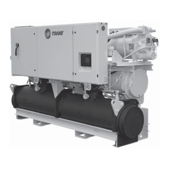
Unit Description Figure 1 - Component location for Typical RTWD unit 1 = Control panel 2 = Power cable gland plate for customer wiring 3 = Tracer CH530 or DynaView 4 = Suction line 5 = Oil separator 6 = Condenser water outlet... - Page 21 A list of the contractor responsibilities typically maintenance and to balance/trim the system. associated with the RTWD installation process is • Install fl ow switches or equivalent devices in both provided in Table 8.
- Page 22 Clearances If the refrigerant pressure is below the values in table 9 below, call a qualifi ed service organization and the appropriate Trane sales offi ce. Provide enough space around the unit to allow the installation and maintenance personnel unrestricted access to all service points.
-
Page 23: Installation - Mechanical
Remove Shipping Spacers The chiller should be moved by lifting or by the base rail For all RTWD 060-120 and all RTUD 060-120, remove and designed for forklifting. Refer to the unit model number discard the two shipping spacers with four bolts, located for more details. -
Page 24: Evaporator Piping
Evaporator Piping Reversing Water Boxes Thoroughly fl ush all water piping to the RTWD/RTUD Water boxes on the evaporator and condenser can NOT unit before making the fi nal piping connections to be rotated or swapped end for end. Altering the water the unit. -
Page 25: Evaporator Drain Flow Proving Devices
fl ow switch installation are outlined below. CAUTION! Evaporator Damage! For all RTWD-RTUD units, chilled water pumps MUST be controlled by the Trane CH530 to avoid catastrophic damage to the evaporator due to freezing. • Mount the switch upright on a horizontal portion of water outlet pipe, with a minimum of 5 pipe diameters run on each side of the switch. - Page 26 Evaporator Piping Figure 4 - 2 pass Evaporator Pressure Drop curves Waterside Pressure Drop - 50 Hz Units - 2 Pass Evaporator 100.0 1-E1AM2 2-E1AM1 3-E1AMJ 4-E2AM1-E2AM2 5-E2AMJ 6-E3AM2-E3AM3 7-E3AMJ-E4AMJ 8-E4AM1 9-E5AM1 10.0 10-E5AM2 11-E5AMJ 10.0 100.0 Water Flow l/s Select unit evaporator and limits according to General data table.
-
Page 27: Condenser Piping
(or city water) condensing systems should include a treatment specialist be engaged to determine what pressure reducing valve and a water regulating valve. water treatment, if any, is required. Trane assumes no Pressure reducing valve should be installed to reduce responsibility for equipment failures which result from water pressure entering the condenser. - Page 28 Condenser Piping Figure 6 - Condenser Pressure drop curves Waterside Pressure Drop - 50 Hz Units - Condenser 1-C1AM2 100.0 2-C1AMJ 3-C2AM3 4-C2AM2 5-C2AMJ 6-C3AM2-C3AM3 7-C3AMJ-C4AMJ 8-C4AM2 9-C5AM2 10-C5AM1 11-C5AMJ 10.0 10.0 100.0 Water Flow l/s Select unit Condenser and limits according to General data table. RLC-SVX14H-GB...
-
Page 29: Relief Valves
Note: Units can be ordered with “Dual Relief Valve” calibration installed on refrigerant piping or on the options. Model number digit 16 is a “2”. RTWD units this condenser must not exceed 25 bar. option will have 4 total relief valves. -
Page 30: Split System Installation
Split system installation RTUD Installation The installation of a split system offers a good economic alternative to satisfy the chilled water demand for cooling a building, particularly in the case of new construction. Releasing the Nitrogen Holding Charge The nitrogen holding charge can be released into the atmosphere. -
Page 31: Condenser Above The Compressor Chiller
Split system installation Condenser Above the Compressor Chiller Figure 9 - Condenser above the compressor chiller Inverted Trap Inverted Trap Heght equal to Height equal to top of Condenser top of Condenser Liquid Line Liquid Line Discharge Line Discharge Line Trap RESTRICTIONS •... -
Page 32: System Confi Guration
Split system installation System Confi guration Equivalent Line Length The system can be confi gured in any of the primary To determine the appropriate size for fi eld installed arrangements as shown in Figure 8 and 9. The liquid and discharge lines, it is fi rst necessary to confi... -
Page 33: Liquid Line Sizing
Split system installation Liquid Line Sizing Discharge (Hot Gas) Line Sizing Trane recommends that the liquid line diameter be as The discharge lines should pitch downward, in the small as possible, while maintaining acceptable pressure direction of the hot gas fl ow, at the rate of 12.5 mm per drop. -
Page 34: Refrigerant Charge Determination
Outdoor Air Temperature Sensor Installation Requirements The outdoor air temperature sensor is optional for the RTWD water cooled units, but is a required sensor for the RTUD compressor chiller units. The sensor is required as an important input to the condenser fan control algorithm as well as for the low outdoor air ambient lockout feature. -
Page 35: Fan Control For The Remote Air Cooled Condenser
Split system installation Fan Control for the Remote Air Cooled Since the condenser is provided separately from the Condenser RTUD compressor chiller, the RTUD electrical panel design does not provide for condensing unit’s control The CH530 Controls for the RTUD compressor chiller power requirements. -
Page 36: Rtud Condenser Elevation Setting
Split system installation RTUD Condenser Elevation Setting Condenser elevation setting allows proper EXV operation. Failure to properly set the elevation can result Condenser elevation setting is a require input during in low pressure cutout trips, or low differential pressure startup of an RTUD chiller, and is accessible in trips during startup or large load transients, as well as TechView, on the Unit View Screen. -
Page 37: General Electrical Recommendations
General Electrical Recommendations Electrical Parts • For variable frequency drives or other energy storing components provided by Trane or others, refer to the When reviewing this manual keep in mind. appropriate manufacturer’s literature for allowable • All fi eld-installed wiring must be in accordance with waiting periods for discharges capacitors. - Page 38 Failure -Unit Displacement Power factor to do so may result in personal injury or death. CAUTION! Units including RTWD HSE units must not - Disconnect switch size (A) be linked to the neutral wiring of the installation. Units...
- Page 39 Table 13 - RTWD Standard Effi ciency R134a Unit size Unit Type Digit 12 Unit Application Digit 15 Evap Application Digit 21 Comp Starter digit 24 Compressor M2 LoVi M2 LoVi M2 HiVi M2 HiVi M2 HiVi M2 HiVi N1 LoVi...
- Page 40 Table 13 - RTWD Standard Effi ciency R134a (Continued) Unit size Unit Type Digit 12 Unit Application Digit 15 Evap Application Digit 21 Comp Starter digit 24 Compressor N1 LoVi N1 LoVi N1 HiVi N1 HiVi N1 HiVi N1 HiVi...
- Page 41 Table 14 - RTWD High Effi ciency R134a Unit size Unit Type Digit 12 Unit Application Digit 15 Evap Application Digit 21 Comp Starter digit 24 Compressor K1 LoVi K1 HiVi K1 HiVi K2 LoVi K2 HiVi K2 HiVi K2 LoVi...
- Page 42 Table 14 - RTWD High Effi ciency R134a (Continued) Unit size Unit Type Digit 12 Unit Application Digit 15 Evap Application Digit 21 Comp Starter digit 24 Compressor L1 HiVi L1 LoVi L1 HiVi L1 HiVi L2 LoVi L2 HiVi...
- Page 43 Table 14 - RTWD High Effi ciency R134a (Continued) Unit size Unit Type Digit 12 Unit Application Digit 15 Evap Application Digit 21 Comp Starter digit 24 Compressor M1 HiVi M1 HiVi M1 LoVi M1 HiVi M1 HiVi M2 LoVi...
- Page 44 Table 14 - RTWD High Effi ciency R134a (Continued) Unit size Unit Type Digit 12 Unit Application Digit 15 Evap Application Digit 21 Comp Starter digit 24 Compressor M2 HiVi N1 LoVi N1 HiVi N1 HiVi N1 LoVi N1 HiVi...
- Page 45 Table 15 - RTWD Extra High Effi ciency R134a Unit size Unit Type Digit 12 Unit Application Digit 15 Evap Application Digit 21 Comp Starter digit 24 Compressor M2 LoVi M2 LoVi M2 HiVi M2 HiVi M2 HiVi M2 HiVi...
- Page 46 Table 15 - RTWD Extra High Effi ciency R134a (Continued) Unit size Unit Type Digit 12 Unit Application Digit 15 Evap Application Digit 21 Comp Starter digit 24 Compressor M2 HiVi M2 HiVi M2 HiVi N1 LoVi N1 LoVi N1 HiVi...
- Page 47 Table 16 - RTWD High Seasonal Effi ciency R134a Unit size Unit Type Digit 12 Unit Application Digit 15 Evap Application Digit 21 Comp Starter digit 24 Compressor K1 LoVi K1 HiVi K1 HiVi K2 LoVi K2 HiVi K2 HiVi...
- Page 48 Table 16 - RTWD High Seasonal Effi ciency R134a (Continued) Unit size Unit Type Digit 12 Unit Application Digit 15 Evap Application Digit 21 Comp Starter digit 24 Compressor L1 LoVi L1 HiVi L1 HiVi L2 LoVi L2 HiVi L2 HiVi...
- Page 49 Table 16 - RTWD High Seasonal Effi ciency R134a (Continued) Unit size Unit Type Digit 12 Unit Application Digit 15 Evap Application Digit 21 Comp Starter digit 24 Compressor M1 LoVi M1 HiVi M1 HiVi M2 LoVi M2 HiVi M2 HiVi...
- Page 50 Table 16 - RTWD High Seasonal Effi ciency R134a (Continued) Unit size Unit Type Digit 12 Unit Application Digit 15 Evap Application Digit 21 Comp Starter digit 24 Compressor N1 LoVi N1 HiVi N1 HiVi N2 LoVi N2 HiVi N2 HiVi...
- Page 51 Table 17 - RTUD R134a Unit size Unit Type Digit 12 Unit Application Digit 15 Evap Application Digit 21 Comp Starter digit 24 Compressor K1 HiVi K1 HiVi K2 HiVi K2 HiVi K2 HiVi K2 HiVi L1 HiVi L1 HiVi L1 HiVi L1 HiVi L2 HiVi...
- Page 52 Table 17 - RTUD R134a (Continued) Unit size Unit Type Digit 12 Unit Application Digit 15 Evap Application Digit 21 Comp Starter digit 24 Compressor L2 HiVi L2 HiVi M1 HiVi M1 HiVi M1 HiVi M1 HiVi M2 HiVi M2 HiVi M2 HiVi M2 HiVi N1 HiVi...
- Page 53 Table 17 - RTUD R134a (Continued) Unit size Unit Type Digit 12 Unit Application Digit 15 Evap Application Digit 21 Comp Starter digit 24 Compressor M2 HiVi M2 HiVi N1 HiVi N1 HiVi N1 HiVi N1 HiVi N1 HiVi N1 HiVi N2 HiVi N2 HiVi N1 60 HiViN2 60 HiVi N1 HiVi...
- Page 54 Table 18 - RTWD High Effi ciency R1234ze Unit size Unit Type Digit 12 Unit Application Digit 15 Evap Application Digit 21 Comp Starter digit 24 Compressor M1 HiVi M1 HiVi M1 HiVi M1 HiVi M1 HiVi M1 HiVi M2 HiVi...
- Page 55 Table 18 - RTWD High Effi ciency R1234ze (Continued) Unit size Unit Type Digit 12 Unit Application Digit 15 Evap Application Digit 21 Comp Starter digit 24 Compressor M2 HiVi N5 HiVi N5 HiVi N5 HiVi N5 HiVi N5 HiVi...
- Page 56 Table 19 - RTWD High Seasonal Effi ciency R1234ze Unit size Unit Type Digit 12 Unit Application Digit 15 Evap Application Digit 21 Comp Starter digit 24 Compressor M1 HiVi M1 HiVi M1 HiVi M1 HiVi M1 HiVi M1 HiVi...
- Page 57 Table 19 - RTWD High Seasonal Effi ciency R1234ze (Continued) Unit size Unit Type Digit 12 Unit Application Digit 15 Evap Application Digit 21 Comp Starter digit 24 Compressor M2 HiVi N5 HiVi N5 HiVi N5 HiVi N5 HiVi N5 HiVi...
- Page 58 Table 19 - RTWD High Seasonal Effi ciency R1234ze (Continued) Unit size Unit Type Digit 12 Unit Application Digit 15 Evap Application Digit 21 Comp Starter digit 24 Compressor N6 HiVi N6 HiVi N6E2 60 N6E2 60 N6E2 60 N6E2 60...
-
Page 59: Installer-Supplied Components
RTWD SE, HE, XE and RTUD or bottom side for RTWD HSE. Additional grounds may be required for each 110 volt power supply to the unit. -
Page 60: Installation - Electrical
® diagnostics to prevent the build up of pump heat. The Model RTWD Series R chiller requires a fi eld- supplied control voltage contact input through a fl ow proving switch 5S5 and an auxiliary contact 5K9 AUX. -
Page 61: Alarm And Status Relay Outputs (Programmable Relays)
CAUTION Evaporator Damage! A Low Chilled Water Temp. diagnostic (non-latching) (unless also accompanied by an Evap Leaving Water The RTWD units do NOT require evaporator pump Temperature Sensor Diagnostic) control. All systems with a remote condenser REQUIRE chilled water pumps must be controlled by the Trane... - Page 62 Installation – Electrical Table 21 - Alarm and Status Relay Output Confi guration Table Diagnostics Alarm - Latching This output is true whenever there is any active diagnostic that requires a manual reset to clear, that affects either the Chiller, the Circuit, or any of the Compressors on a circuit.
-
Page 63: Relay Assignments Using Techview
The default assignments for the four available relays of control panel. the RTWD Alarm and Status Package Option are: Connect low voltage leads to terminal strip locations Table 22 - Default assignments on 1A5, J2-3 and 4. - Page 64 Installation – Electrical Ice Building Option Upon contact closure, the CH530 will initiate an ice building mode, in which the unit runs fully loaded at all CH530 provides auxiliary control for a customer times. Ice building shall be terminated either by opening specifi...
- Page 65 Installation – Electrical If the ECWS input develops an open or short, the LLID The J2-3 and J2-6 terminal is chassis grounded and will report either a very high or very low value back to terminal J2-1 and J2-4 can be used to source 12 VDC. the main processor.
- Page 66 Installation – Electrical Reset ratio Start reset Maximum reset Increment SI Factory default Reset type range range range units value Return 10 to 120% 2.2 to 16.7°C 0.0 to 11.1°C Outdoor 80 to -80% 10 to 54.4°C 0.0 to 11.1°C The equations for each type of reset are as follows: In addition to Return and Outdoor Reset, the MP provides a menu item for the operator to select a...
-
Page 67: Communications Interface Options
Communications Interface options External Analog Output Note: For the RTWD and RTUD chillers, the High Pressure Cutout Setting is replaced by the Software As an option, CH530 provides a 2-10 VDC analog output High Pressure Cutout setting, (The Software HPC is to indicate condenser pressure. - Page 68 The following equations are applied: gauge or absolute as long as they are consistent. For multiple circuit chillers, such as RTWD, the refrigerant differential pressure used in the calculation will be the lowest differential pressure of all of the running circuits.
-
Page 69: Optional Tracer Communications Interface
• Termination resistors are required • 105 ohms at each end for Level 4 wire • 82 ohms at each end for Trane “purple” wire • LCI-C topology should be daisy chain • Zone sensor communication stubs limited to 8 per link, 15 m each (maximum) •... - Page 70 Communications Interface options Table 24 - LonTalk Points List Inputs/Outputs Variable type SNVT / UNVT Input Chiller Enable/Disable binary Start (1)/stop (0) SNVT_switch Chilled Water Setpoint analog temperature SNVT_temp_p Capacity Limit Setpoint analog % current SNVT_lev_percent Chiller Mode Note 1 SNVT_hvac_mode Outputs Chiller On/Off...
-
Page 71: Operating Principles
• AFD (Adaptive Frequency Drive) on HSE versions Disconnect all electric power, including remote disconnects before servicing. Follow proper lockout/ Components of a typical RTWD/RTUD unit are identifi ed tagout procedures to ensure the power can not be in the following diagram. - Page 72 Operating Principles Figure 14 - Components (back view) 1 = Circuit 1 2 = Circuit 2 A = Discharge service valve B = Compressor junction box C = Filter D = Liquid level sensor E = Oil cooler (application dependant) F = Gas pump (behind frame) G = Baserail for forklifting (option) RLC-SVX14H-GB...
-
Page 73: Refrigeration (Cooling) Cycle
Cycle Description provides an almost oil-free refrigerant to the shells to maximize heat transfer performance, while providing The refrigeration cycle for the RTWD/RTUD chiller can be lubrication and rotor sealing to the compressor. The described using the pressure-enthalpy diagram shown lubrication system ensures long compressor life and in Figure 15. - Page 74 For RTWD units, a discharge baffl e within the condenser level is maintained. shell distributes the compressed refrigerant vapor evenly across the condenser tube bundle.
- Page 75 Operating Principles Figure 16 - RTWD/RTUD Typical Refrigerant Circuit Compressor A - circuit 1 High Pressure Cutout Switch Comp. Discharge Temp Sensor Cond. Rfgt. Pressure Trans. Load/Unload and Step Solenoids Oil Separator Circuit 1 Note : The schematic above is typical refrigerant fl ow...
-
Page 76: Oil System Operation (Rtwd/Rtud)
It then goes through the service valve and fi lter. At this point it travels through the master oil valve. Then it provides oil injection and bearing lubrication. Figure 17 - RTWD/RTUD Oil Circuit 1 = Evaporator refrigerant pressure transducer 2 = Condenser (RTWD only) - Page 77 Operating Principles Compressor Motor Figure 18 - RTWD Compressor A two-pole, hermetic, induction motor (3600 rpm at 60 hz, 3000 rpm at 50hz) directly drives the compressor rotors. The motor is cooled by suction refrigerant gas from the evaporator, entering the end of the motor housing through the suction line.
-
Page 78: Rtwd Operating Map
RTWD Operating map RLC-SVX14H-GB... -
Page 79: Pre-Start Checkout
• Verify that all refrigerant valves are “OPEN”. trained in handling live electrical components perform these tasks. Failure to follow all electrical safety RTWD HSE version precautions when exposed to live electrical components could result in death or serious injury. - Page 80 Trane assumes live electrical components. Have a qualifi ed licensed no responsibility for equipment failures which result...
- Page 81 Pre-Start Checkout Unit Voltage Imbalance Proper compressor motor electrical phasing can be quickly determined and corrected before starting the Excessive voltage imbalance between the phases of a unit. Use a quality instrument, such as the Associated threephase system can cause motors to overheat and Research Model 45 Phase Sequence Indicator.
- Page 82 Failure to disconnect power before servicing could result in death or serious injury. RTWD HSE version • Time before to work on the electrical panel of the unit: once the AFD is off (confi rmed by the extinction of the display), it is mandatory to wait one minute before working on the electrical panel.
-
Page 83: Start-Up
Pre-Start Checkout Start-up Seasonal Unit Start-Up Procedure 1. Close all valves and re-install the drain plugs in the If the pre-start checkout, has been completed, the unit is evaporator and condenser heads. ready to start. 2. Service the auxiliary equipment according to the 1. -
Page 84: Service And Maintenance
1 to 3°C above that of leaving condenser water at Use only refrigerants specifi ed on the unit nameplate full load. (R134a or R1234ze) and Trane OIL 048E on SE, HE, PE Monthly Maintenance and Checks versions with R134a, OIL00317 on HSE version with 134a and OIL066E or OIL067E for R1234ze. -
Page 85: Annual Maintenance
Hazardous Voltage! Note: Do not swap R134a by R1234ze without Disconnect all electric power, including remote intervention of Trane Service organization for advice disconnects and discharge all motor start/run capacitors on technical changes. before servicing. Follow proper lockout/tagout procedures to ensure the power cannot be inadvertently energized. -
Page 86: Service Procedures
The use of untreated or improperly treated water in a acceptable working load limit. Failure to properly lift RTWD may result in scaling, erosion, corrosion, algae or waterbox could result in death or serious injury. slime. It is recommended that the services of a qualifi ed... - Page 87 Service and Maintenance CAUTION 1. Select the proper lift connection device from Table 24. The rated lifting capacity of the selected lift To prevent injury, do not place hands or fi ngers between connection device must meet or exceed the published waterbox and condenser tubesheet.
- Page 88 Failure to follow these instructions could result in death or serious injuries. All RTWD Units 1. Store waterbox in a safe and secure location and position. Note: Do not leave waterbox suspended from lifting device.
-
Page 89: Waterbox Weights
Service and Maintenance Waterbox Weights Table 29 - RTWD/RTUD Evaporator Waterbox Weights Standard Grooved Pipe Waterbox Model Size Effi ciency Waterbox Evap Pass Weight (kg) Lifting connection RTWD / RTUD 060, 070, 080 HE / HSE Supply 2 or 3 21.5... -
Page 90: Compressor Oil
To prevent oil sump heater burnout, open the unit main power disconnect switch before removing oil from the compressor. Trane Polyolester Oil is the approved oil for the RTWD/ RTUD units. Polyolester oil is extremely hygroscopic meaning it readily attracts moisture. The oil can not be stored in plastic containers due to the hygroscopic properties. -
Page 91: Removing Compressor Oil
Service and Maintenance Replacing the Oil Filter 6. If the level is below 10cm, there is not enough oil in the sump. This can occur from not enough oil The fi lter element should be changed if the oil fl ow is in the system or more likely, oil migration to the suffi... -
Page 92: Refrigerant Charge
Refer to General Data Tables and Unit nameplate for refrigerant charge information. Figure 24 - Recommended Oil Filter Replacement GP2 / RTWD Clean FilterVersus Recommended Filter Replacement GP2 / RTWD Clean Filter Versus Recommended Filter Replacement Line CH530 RTWD Oil Pressure Protection Scheme Line... -
Page 93: Freeze Protection
• Low evaporator refrigerant temperature limit 8. Inspect replacement fi lter element and lubricate • Erratic liquid level control o-ring with Trane OIL00048. • Low unit capacity • Low discharge superheat (especially at high loads) NOTE: Do not use mineral oil. It will contaminate the •... -
Page 94: Recommended Service Routine Frequencies
As a commitment to our customers, we have created a wide service network staffed with experienced factory- authorized technicians. At Trane we offer all the benefi ts of after sales service direct from the manufacturer and we are committed to our mission statement to provide effi cient customer care. -
Page 95: Additional Services
Additional services Oil analysis Annual cooling tower maintenance Trane Oil Analysis is a predictive tool used to detect This Service includes the inspection and maintenance of minor issues before they become major problems. It the cooling tower at least once a year. - Page 96 HVAC systems, comprehensive building services, and parts. For more information, visit www.Trane.com. Trane has a policy of continuous product and product data improvement and reserves the right to change design and specifications without notice. © 2017 Trane All rights reserved...
Need help?
Do you have a question about the RTWD and is the answer not in the manual?
Questions and answers