Table of Contents
Advertisement
Advertisement
Table of Contents
Troubleshooting

Related Manuals for Servomex DF-310E


Summary of Contents for Servomex DF-310E
- Page 1 Oxygen Analyzer DF-310 E OPERATOR MANUAL...
- Page 2 No part of this publication may be reproduced, stored in a retrieval system or transmitted in any form, or by any means including electronic, mechanical, photocopying, recording or otherwise without prior written permission of Servomex Corporation. Stablex, Bi-Strata and are trademarks of Servomex Corporation. VCR is a registered trademark of the Cajon Company.
- Page 3 For more information or if you have questions, please do not hesitate to go to our website at Servomex.com, or contact your local Servomex Business Center as found on the back cover of this manual.
- Page 4 (see Shipping in the Service section). Installation and Maintenance The DF-310E Process Oxygen Analyzer will provide years of accurate and dependable service if it is set up, operated and maintained properly. It is essential to make a careful and complete installation as outlined in the Installation and Setup section of this manual.
-
Page 5: Table Of Contents
Sample Gas Scale Factor ..................34 Sample Flow Rate and Pressure................35 6.3.1 Flow Rate Effects on Sensor Performance ..........36 6.3.2 Checking for Plumbing Leaks using Flow Rate Effects ......36 6.3.3 Background Gas Effects on Indicated Flow Rate........36 6.3.4 Regulator Requirements ................36 Index DF-310E... - Page 6 Set-Up Menu......................67 8.4.1 Alarms .....................68 8.4.2 Analog Outputs ..................70 8.4.3 Comm Port....................73 8.4.4 Gas Scale Factor..................74 8.4.5 Display Setup...................74 8.4.6 Clock .......................75 The Password Menu ....................76 Maintenance......................77 8.6.1 Replenish Solution Reminder ..............78 8.6.2 Oxygen Calibration ..................79 8.6.3 Diagnostics ....................86 DF-310E Index...
- Page 7 Shipping ......................103 Theory of Operation............. 105 10.1 The Oxygen Sensor ................... 105 10.2 The Electrolyte Conditioning System ..............106 Safety ..................107 11.1 Electrolyte Solution MSDS................109 11.2 Replenishment Solution MSDS................115 Warranty ................119 Index ..................121 Index DF-310E...
-
Page 8: Table Of Figures
1.1 Table of Figures Figure 1: DF-310E Oxygen Analyzer ................. 12 Figure 2: Major Internal Components................. 13 Figure 3: Quick Disconnect Fitting at Flowmeter..............15 Figure 4: DC Power Connector – J3 ................... 16 Figure 5: Data Display Screen .................... 17 Figure 6: Rear Panel...................... - Page 9 Figure 62: Test Relay Screen ....................90 Figure 63: Memory Test Screen ..................90 Figure 64: EXT Functions....................91 Figure 65: Fuse Locations for DC Power Supply and Battery Backup ........102 Figure 66: Printed Circuit Board Assembly ...............102 Figure 67: Schematic of Servomex Oxygen Sensor............105 Index DF-310E...
-
Page 11: Cautions
There are a number of warnings and cautions that must be observed to avoid damage to the analyzer as well to insure the safety of its users. The analyzer must be operated in a manner specified in this manual. Servomex cannot be responsible for direct or consequential damages that result from installing or operating the analyzer in a manner not described in this manual. - Page 12 For best performance at initial start or anytime the electrolyte is changed, it is important to allow the sensor to sit with electrolyte in it for 60 minutes before the gas is allowed to flow through the sensor. DF-310E Cautions...
-
Page 13: Specifications
0 - 1 X.XXX% 1 - 10 XX.XX H00P25 0-25% 0 - 2.5 X.XX% 2.5 - 25 XX.X *Scale A applies to High Resolution models only. Scale B extends down to 0 ppm or 0% on Standard Resolution models. Specifications DF-310E... - Page 14 Contacts failsafe to alarm condition upon loss of power. Not designed to switch AC power. POWER REQUIREMENTS 100 – 240 VAC (auto-switching), 1.3A, 50/60 Hz or 24 VDC (–2/+4VDC), 1A, 25 Watts; Optional Sample Pump 6W additional EMI SENSITIVITY DF-310E Specifications...
- Page 15 S, Cl , NO , SO , HCl, etc. GAS SAMPLE MOISTURE CONTENT No limit (avoid condensation) OIL/SOLVENT MIST <0.03 mg/L Standard limit >0.03 mg/L Use filter SOLID PARTICLES <0.01 mg/L Standard limit, Use filter if >0.01 mg/L Specifications DF-310E...
-
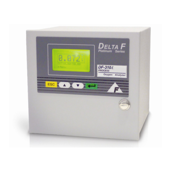
Page 16: Figure 1: Df-310E Oxygen Analyzer
TEMP - 485-TX + UNUSED 232-TX SNSR + 232-RX SNSR - 485-RX - SE+ (H+) UNUSED SE - 485-TX - GND (H-) 232-GND 1/8" COMPRESSION 1.06 [26.92] SAMPLE INLET (OPTIONAL 1/4" VCR COMPATABLE MALE) Figure 1: DF-310E Oxygen Analyzer DF-310E Specifications... -
Page 17: Installation And Setup
The screens shown in this manual have values that may not match the actual values displayed during your setup. ROTOMETER VALVE (optional) POWER SWITCH ELECTROLYTE RESERVOIR WITH MIN-MAX LINES OXYGEN SENSOR SENSOR MOUNTING THUMB SCREWS Figure 2: Major Internal Components Installation and Setup DF-310E... -
Page 18: Adding Electrolyte
The sensor is shipped dry and must be charged with electrolyte before it is operated. NOTE Use only Hummingbird E-lectrolyte Blue for the DF-310E Oxygen Analyzer. Failure to do so will void warranty. Install one bottle. NOTE Do not apply power before adding electrolyte and thoroughly purging sample line. -
Page 19: Sample Gas Connections
Over-pressurizing the sensor can result in permanent damage to the sensor. Limit the backpressure to the analyzer to ±1 psig. NOTE Allow gas with very little oxygen to flow through the analyzer for approximately 60 minutes before powering up. Installation and Setup DF-310E... -
Page 20: Electrical Power Connections
AC Powered Units - Open the front door, locate the power switch and turn it on. See Figure 2. DC Powered Units - Turn on the remote 24 VDC power source, open the front door, locate the power switch and turn it on. See Figure 2. DF-310E Installation and Setup... -
Page 21: Startup Process
After power up, the analyzer will undergo a series of Diagnostic Procedures. After approximately 5 seconds, the Servomex Corporation logo is displayed. After 30 seconds, a WAIT message appears for 1.5 minutes. A display then appears that is similar to Figure 5 (values shown are only representative). -
Page 22: Figure 6: Rear Panel
UNUSED EXT-2 - TEMP + 485-RX + TEMP - 485-TX + UNUSED 232-TX SNSR + 232-RX SNSR - 485-RX - SE+ (H+) UNUSED SE - 485-TX - GND (H-) 232-GND AC INLET Figure 6: Rear Panel DF-310E Installation and Setup... -
Page 23: Options
PUMP -, + connections on the rear panel connector J4. The contacts can be used to send a signal indicating the status of the internal pump or to control an external, Servomex supplied pump that is powered from a separate source. -
Page 24: Low Flow Alarm
6 hours Table 1: Battery Operation Time NOTE Use only Servomex P/N 16337070 when replacing the NiMH battery pack. In the event that the NiMH Battery Option is installed in an analyzer that also has the Case Purge Option, the NiMH Battery system must be disabled. -
Page 25: Flow Control Valve
Note: If the analyzer is equipped with a VCR welded sample inlet connection, there is a .010 inch orifice at the inlet to the sensor which requires 15-20 psig of pressure. NOTE: For additional information on the proper purging of regulators after installation see page 37. Options DF-310E... -
Page 26: Figure 7: Plumbing Configuration Options
Figure 7: Plumbing Configuration Options DF-310E Options... -
Page 27: Combined Filter/Pressure Regulator
2 connected to the Analyzer's sample inlet fitting. For mist coalescing and collection for draining, plumb the filter with port 1 connected to the Analyzer's sample inlet fitting. NOTE: For additional information on the proper purging regulators after installation see page 37 Options DF-310E... -
Page 28: Stainless Steel Outlet Tubing
The lock is supplied with two keys. If the analyzer is operating, the key lock does not prevent adjustments from the front panel. Password Protection, described in the User Interface section DF-310E Options... -
Page 29: 4-20Ma Analog Output
Use of this function provides information than could be interpreted remotely as an alarm or non-standard condition. See page 66 for additional information on the Sensor Off function. 5.11Relays Up to four optional form C (SPDT) relays (contact closures) are available to Options DF-310E... -
Page 30: Communication Port - Rs232/485
The optional expanded range scale allows the analog output scaling to be automatically expanded to a larger value when the primary scaling range is exceeded. See page 72 for additional information. 5.14Panel Mount A panel mount option is available. See Figure 11 and Figure 12 below for details. DF-310E Options... -
Page 31: Figure 11: Panel Mount Configuration
8.33 [211.48] 9.26 [235.08] .30 [7.62] 9.36 [237.87] 9.97 [253.11] Figure 11: Panel Mount Configuration Ø.22 [Ø5.59] 4 PL 4.63 [117.60] 8.44 [214.38] 1.91 [48.39] .21 [5.27] 8.95 [227.33] 9.37 [237.87] Figure 12: Cutout Dimensions for Panel Mount Options DF-310E... -
Page 32: Rack Mount
Following are the dimensions for the hole cutout and mounting screws. The connecting cable must be shielded with the ground attached only to the stud on the rear of the analyzer and wired as shown in Figure 16. DF-310E Options... -
Page 33: Figure 15: Remote Display
THREADED MOUNTING STUDS 4 PLS .25 [6.4] .14 [3.5] 3.30 [83.8] 3.650 [92.7] 1.63 [41.3] .40 [10.1] PHANTOM LINE REPRESENTS THE PANEL CUT OUT TO ALLOW .74 [18.7] CLEARANCE FOR DISPLAY ELECTRONICS. .69 [17.4] 5.45 [138.4] Figure 15: Remote Display Options DF-310E... -
Page 34: Case Purge
5.18Case Purge NOTE: The case purge option is available on AC powered analyzers only. The DF-310E analyzer can be equipped with an inert gas (nitrogen) purge system. The purge system provides improved protection against an explosion hazard by purging the enclosure to a concentration level below the lower explosive limit. -
Page 35: Figure 17: Case Purge Option
9.70 [246.33] FLOW SWITCH 8.33 [211.48] 9.07 [230.38] SAMPLE OUTLET 1/8" COMPRESSION CABINET PURGE FLOWMETER AND CONTROL VALVE 4.21 [106.93] 7.75 [196.75] SAMPLE INLET 1/8" COMMPRESSION OR 1/4" VCR COMPATIBLE MALE 2.05 [52.07] Figure 17: Case Purge Option Options DF-310E... -
Page 37: Sample Gas Preparation And Delivery
Table 2: Maximum Allowable Acid Gas Limits Contact the local Servomex Business Center for recommendations on using the STAB-EL sensor on acid gases other than those listed above. The STAB-EL limits shown in the table represent rough guidelines for continuous exposure. -
Page 38: Sample Gas Scale Factor
Servomex offers a broad range of scrubbers for applications in severe environments. Standard scrubber columns are available in various sizes, and in single or dual bed configurations. -
Page 39: Sample Flow Rate And Pressure
Table 3: Gas Scale Factors 6.2.1.1 Disclaimer The method used to correct the calibration of the DF-310E Oxygen Analyzer for measurement in non-nitrogen background gases is derived from a well- known theoretical mass transfer equation. This equation accounts for the change in oxygen diffusion rates through different gases. -
Page 40: Flow Rate Effects On Sensor Performance
(1.0 - 2.0 scfh) no regulator is required. A flow change of ±1.0 scfh may result in a small change to the oxygen reading. DF-310E Sample Gas Preparation and Delivery... -
Page 41: Pressure Regulator Purge
If the analyzer is not vented to atmosphere, the sensor pressure is influenced by the conditions downstream of the analyzer. A recalibration under your operating conditions may be desirable to remain within the stated accuracy Sample Gas Preparation and Delivery DF-310E... -
Page 42: Sample Outlet Backpressure Effects
6.4 Sample Gas Compatibility There are a wide range of considerations in determining the gas sample compatibility of the Process Oxygen Analyzer. Servomex attempts to identify all pertinent application details prior to quoting and order processing. All non-typical applications concerning gas sample compatibility must be reviewed by our in-house Application Engineers. -
Page 43: Gas Solubility In Aqueous Koh Solution
O), however, do not affect the electrode or sealing materials, or interfere with the O reduction/oxidation reactions. Contact the local Servomex Business Center for recommendations on a specific application. 6.4.3 Reactivity with KOH Electrolyte Many process sample streams contain various concentrations of acid gases. -
Page 44: Sample Gas Temperature
33 for more detail. Contact the local Servomex Business Center for recommendations on using the STAB-EL sensor on acid gases other than those listed. 6.4.6 Sample Gas Temperature Gas temperature should not exceed 50 °C (122° F), nor should it fall below 0°... -
Page 45: Calibration Cylinder Regulators
For systems where the gas sample is not vented to atmosphere, the analyzer outlet should remain connected in the same manner during calibration, if possible. This ensures that downstream pressure effects on the sensor are the Sample Gas Preparation and Delivery DF-310E... -
Page 46: Background Gas Effects On Calibration
(factory calibration gas) versus the diffusion rate in the user’s calibration gas. The Sample Gas Preparation and Delivery section discusses the proper setting of the gas scale factor option during calibration as well as during process gas measurement. DF-310E Sample Gas Preparation and Delivery... -
Page 47: Connecting To External Devices
Table 4: Comm Port (J8) Connector Pinout TEMP + 485-RX + TEMP - 485-TX + UNUSED 232-TX SNSR + 232-RX SNSR - 485-RX - SE+ (H+) UNUSED SE - 485-TX - GND (H-) 232-GND Figure 18: J7/J8 Connector Wiring Connecting to External Devices DF-310E... -
Page 48: Relay Ports
When connecting the Process Oxygen Analyzer to a computer via an RS-232 or RS-485 communication cable, a Ferrite Sleeve is required around the cable in a single-turn configuration. It is recommended that the proper Servomex cable be used for this purpose. 7.2 Relay Ports Connections to four optional form C (SPDT) relays (contact closures) are provided on the rear of the analyzer at connector J1 and J2. -
Page 49: Analog Outputs
2. Label and remove all connections from the rear of the analyzer. 3. Open the door and disconnect the sensor and display cables. See page 13. 4. Remove the two screws from the rear of the unit. See page 18. Connecting to External Devices DF-310E... -
Page 50: 4-20Ma Output
12. With a DVM, confirm that the analog output voltage is proper. If it needs to be adjusted slightly, use the potentiometer located third from the top on the front of the circuit board, above the Servomex symbol. Full Scale Output Voltage Jumper Number 5.0 VDC... -
Page 51: Alignment Procedure For Analog Voltage And Current Loop Outputs
If equipped, the oxygen sensor can be turned on and off remotely through the pins labeled EXT 1 or EXT 2 on the J6 connector. If equipped, the EXT Functions screen, see page 91, will indicate to what set of EXT contacts this option is assigned, either 1 or 2. Connecting to External Devices DF-310E... -
Page 52: Remote Pump Control - J6 Connector
The pump cable should be of sufficient size for the required run (see Table 10 below) and should not share the same conduit as the sensor cable. See the wiring diagram in Figure 30. DF-310E Connecting to External Devices... -
Page 53: Remote Sensor Installations
If factory configured, a switch closure rated at 1A/30VDC can be supplied between the PUMP -, + connections on the rear panel connector J4. The contacts can be used to control a Servomex supplied pump that is powered from a separate 12 VDC, .3 A source. Control of the pump would be accomplished in the same manner as a standard pump. -
Page 54: Sensor On Remote Bracket With Optional Pump
A 0.010 inch orifice is included with 0-50ppm sensors and must be installed at the sensor inlet in order to control gas flow. Contact Servomex for additional information on remote sensor installations. 7.5.1 Sensor on Remote Bracket with Optional Pump... -
Page 55: Sensor In Nema 4 Enclosure
SAMPLE SAMPLE INLET OUTLET SIGNAL OUTPUT 7.42 [188.58] 4.71 [119.75] 2.96 [75.30] 2.96 [75.25] 1.23 [31.36] 1.93 [49.02] AC POWER 2.75 [69.85] 7.00 [177.80] 9.00 [228.60] Figure 25: Remote Sensor Mounted in NEMA 4 Enclosure Connecting to External Devices DF-310E... -
Page 56: Sensor In Nema 7 Enclosure
7.5.3 Sensor in NEMA 7 Enclosure Figure 26: Remote Sensor Mounted in NEMA 7 Enclosure DF-310E Connecting to External Devices... -
Page 57: Temperature Control In R4/R7 Enclosures
In the event that the enclosure temperature must be adjusted, follow the steps below. 1) Obtain a temperature measurement device capable of measuring the desired operating temperature to an accuracy of +/- 2 degrees F. Connecting to External Devices DF-310E... -
Page 58: Remote Sensor Connections - Connector J7
Oxygen Sensor Cable Sizes Distance in Feet Minimum Wire Size 0 – 150 #20 AWG 150 – 250 #18 AWG 250 – 350 #16 AWG 350 – 1000 #14 AWG Table 11: Remote Sensor Cable Sizes DF-310E Connecting to External Devices... -
Page 59: Figure 29: Remote Sensor Connector – J7
TEMP - 485-TX + UNUSED 232-TX SNSR + 232-RX SNSR - 485-RX - SE+ (H+) UNUSED SE - 485-TX - GND (H-) 232-GND Figure 29: Remote Sensor Connector – J7 Figure 30: Remote Sensor/Pump Wiring Diagram Connecting to External Devices DF-310E... -
Page 60: Z-Purge Protection On R4 Enclosure
1.00 [25.40] 7.00 [177.80] 1.93 [49.02] 1.41 [35.93] 2.75 [69.85] 3.14 [79.82] SAMPLE INLET 1/4" COMPRESSION (STD) 7.00 [177.80] 1/4" VCR COMPATIBLE (OPTIONAL) SAMPLE OUTLET 1/4" COMPRESSION Figure 31: Z-Purge Protection on R4 Sensor Enclosure DF-310E Connecting to External Devices... - Page 61 (not in an alarm condition). If the purge switch activates, confirm that the enclosure is “tight” and increase the flow rate as necessary. 11. The analyzer may now be turned on. Connecting to External Devices DF-310E...
-
Page 63: User Interface
8 User Interface 8.1 The Data Display Screen When the DF-310E Process Oxygen Analyzer is powered up, it goes through a series of internal diagnostic tests which take about five seconds. After the tests, the Servomex logo appears for ten seconds. The display will then show the Data Display Screen as shown in Figure 32. - Page 64 The alarm number will clear only after the alarm condition is over. In the case of simultaneous alarms, each will alternately overwrite the display. Successive presses of ESC (as the overwrite is displayed) are necessary to clear the overwrite and DF-310E User Interface...
- Page 65 (> 10 seconds), such as an internal electrical zero calibration. “Memory Error!” indicates that the instrument has failed the boot-up memory test. The letters “CHG”, “BAT” and “LOW” may appear vertically on the right side of the display on units equipped with the NiMH battery backup option. User Interface DF-310E...
- Page 66 DF-310E User Interface...
-
Page 67: Main Menu
Each level in the Main Menu allows the user to access options for setting and testing instrument parameters. Ellipsis (...) after an entry indicates that additional screens follow. User Interface DF-310E... -
Page 68: Keypad Operation
"ABANDON CHANGES?, FOR YES". All parameter changes will be lost if the key is pressed. Select the UPDATE & QUIT choice using to save the changes and automatically return to the previous menu. DF-310E User Interface... -
Page 69: Controls Menu
(downstream) valve should be fully opened and the upstream flow control valve used for flow control. FAILURE TO FOLLOW THESE INSTRUCTIONS MAY CAUSE THE SENSOR TO EXPERIENCE OVER OR UNDER PRESSURE WHICH MAY CAUSE PERMANENT DAMAGE. User Interface DF-310E... -
Page 70: Sensor Polarization
“Analyzer Trouble” relay such that an alarm condition will cause the relay to break the current loop. This method allows a computerized system to be configured to detect an analyzer fault condition whenever the 4-20 mADC signal is below 4 mA. DF-310E User Interface... -
Page 71: P(O)W(E)R Up
Figure 36: Setup Menu Each entry in Figure 36 leads to a sub-menu. To select the desired sub-menu, use the keys to place the asterisk next to it, then press . A new display will be shown as indicated below. User Interface DF-310E... -
Page 72: Alarms
On (USED) or Off (NU). When an unused alarm (NU) is accessed, the display will appear as shown in Figure 39. (Oxygen ALARM 1 is used in the example shown in Figure 40.) To indicate that the alarm is DF-310E User Interface... -
Page 73: Figure 40: Oxygen Alarm Setup Screen (Alarm Used)
8.4.1.3 Low Flow Alarm The FLOW alarm is used to indicate a low flow condition in the sample stream. The optional low flow switch will trip if the gas flow rate drops below the value listed in Table 13. User Interface DF-310E... -
Page 74: Analog Outputs
This method allows a computerized system to be configured to detect an analyzer fault condition whenever the 4-20 mADC signal is below 4 mA. After accessing the Outputs on the Setup Menu, Figure 36, the display will be as shown in Figure 41. DF-310E User Interface... -
Page 75: Figure 41: Recorder Output Setup Menu
0-100 ppm 100 % of Scale 50-85 ppm 35 % of Scale Table 14: Output Scaling on Standard Resolution Analyzer If an invalid Zero to FS window is entered the following error message will be briefly displayed. User Interface DF-310E... -
Page 76: Figure 42: Recorder Output Setup Error
The optional expanded range scale function allows the analog output scaling to be automatically expanded to a larger value when the primary scaling range is exceeded. For example, in the display shown in Figure 41, the analog outputs (0-10 VDC and 4-20 mA) are scaled over the 0 - DF-310E User Interface... -
Page 77: Comm Port
This port operates with an 8 bit, no parity, one stop bit setting. No hardware or software handshaking is used. See the Section on Connecting to External Devices on page 43 for more information. User Interface DF-310E... -
Page 78: Gas Scale Factor
Refer to the section on Calibration on page 79. 8.4.5 Display Setup Access to the controls related to the backlight, brightness and contrast of the display are gained through the display setup menu. See Figure 44 below. DF-310E User Interface... -
Page 79: Clock
When complete, move to the update and quit option with the keys and then hit enter. User Interface DF-310E... -
Page 80: The Password Menu
Figure 45: Clock Setup Screen 8.5 The Password Menu The DF-310E Process Oxygen Analyzer may include optional password protection which can be used to limit access to the Control Menu, the Set-Up Menu, and the Diagnostics Menu. Note: When the Password entry is selected from the Main Menu, a DISABLING ALARMS message appears which notifies the user that the alarms have been temporarily disabled. -
Page 81: Maintenance
Analyzer will not display it again. If the master password is misplaced, contact the local Servomex Business Center. The master password and operator password can be changed as desired after the present master password has been entered. -
Page 82: Replenish Solution Reminder
– the reminder frequency is pre-set at the factory to eight weeks. 8.6.1.3 Assign the “Reminder” Relay The Reminder flag can be assigned to any of the available relays. See the section on relay assignment in the Oxygen Alarm section on page 68. DF-310E User Interface... -
Page 83: Oxygen Calibration
Alternately, the GSF factor can be entered manually. The software in the Analyzer supports the following gases in the GSF calculation: Ammonia Argon Butane Carbon Monoxide Ethane Ethylene Helium Hexane Hydrogen Methane Nitrogen Propylene Table 16: GSF Corrections User Interface DF-310E... -
Page 84: Figure 51: Gas Scale Factor
Note: Scrolling down the gas list from Figure 51 to Figure 52 will displace one line at a time. Because these figures are presented from the top and from the bottom of the gas list, H2 (Hydrogen) and NH3 (Ammonia) appear to be missing. DF-310E User Interface... - Page 85 The GSF for the gas used to calibrate the system may be different from that used during analysis. If the GSF is changed to reflect the composition of the calibrating gas, be sure to reset the GSF before analyzing samples. User Interface DF-310E...
- Page 86 Disclaimer The method used to correct the calibration of the Servomex Oxygen Analyzer for measurement in non-nitrogen background gases is derived from a well known theoretical mass transfer equation. This equation accounts for the change in oxygen diffusion rates through different gases.
-
Page 87: Figure 53: Span Check Menu
5.0 psig or less. The upstream flow control valve is used to set the flow at 1.0 (scfh). If the normal process sample is being supplied to the Analyzer under moderate vacuum User Interface DF-310E... -
Page 88: Figure 54: Calibration Convergence Screen
It may take several minutes before convergence occurs. During convergence, the Analyzer is verifying stability of the reading before accepting the data. After convergence two short beeps will be heard. The Analyzer's electronics can be updated to the new calibration information by selecting Update and Quit. DF-310E User Interface... -
Page 89: Figure 55: Completed Oxygen Calibration Menu
8.6.2.4 New Sensor The New Sensor entry is used after a new sensor is field installed. New sensors are supplied with calibration information. The procedure for installing a new sensor is described in instructions supplied with it. User Interface DF-310E... -
Page 90: Diagnostics
See Section 8.1.1 for details on normal operating conditions. If operating outside normal operating conditions contact Servomex for an application specific recommendation on checking the zero of the instrument in the field. Should Servomex recommend checking the zero baseline calibration of the Analyzer, the DF-310E User Interface... -
Page 91: Figure 57: Sensor Zero Menu
New Sensor zero calibration if the sensor has been field replaced. If the Reset Orig Zero entry is selected, the display will ask Erase?... FOR YES. Press to use the factory set calibration. The Reset Orig Zero line of Figure 57 will disappear. It is User Interface DF-310E... -
Page 92: Figure 58: Zero Cal Warning Screen
Figure 59: Zero Cal Screen Pressing the ESC key at any time aborts the process and returns the user to the SENSOR ZERO DF-310E User Interface... -
Page 93: Figure 60: Zero Cal Not Stable
10% percent steps of full scale from 0% to 100%. After setting the % FS Level, press . The analog output response should match the %FS Level value that was entered. For example, if 80% is entered for the %FS value on a 0-10 User Interface DF-310E... -
Page 94: Figure 62: Test Relay Screen
Next, the microprocessor internal memory (IRAM) is tested, followed by the system “external” random access memory (XRAM). As each portion of the memory is successfully tested an OK will appear at the end of the line. If any memory test fails, DF-310E User Interface... -
Page 95: Figure 64: Ext Functions
After the test has been completed, the display will return to the Diagnostics Menu, Figure 56. Pressing ESC will abort the screen test. If an error message appears, or a pixel is inactive, contact the local Servomex Business Center. -
Page 97: Troubleshooting And Calibration
For process applications containing more significant quantities of acid gases or particulate, or where liquids may be encountered, contact Servomex for a recommendation on calibration verification for your specific case. For Analyzers used in clean gas applications, and operated under Normal Operating Conditions there is no need for zero calibration checks in the field. -
Page 98: Storage Conditions
Operation at elevated temperatures and/or with sample gases at very low dew points will increase the frequency of replenishing the electrolyte. The Oxygen Analyzer is equipped with an Electrolyte Condition alarm to indicate that the DF-310E Troubleshooting and Calibration... -
Page 99: Procedure For Adding Replenishment Solution To The Sensor
Be sure to cap the bottle immediately after use. In an emergency, distilled water can be used as an alternative, however this is not recommend over an extended period. Do not add electrolyte solution to restore the electrolyte level. Do not overfill. Troubleshooting and Calibration DF-310E... -
Page 100: Replaceable Parts List
Hummingbird Brand Replenishment Solution – 100ml 210515 Hummingbird Brand Replenishment Solution – 0.5l 210514 Hummingbird Brand Replenishment Solution – 1.0l 210513 Hummingbird Brand Replenishment Solution – 2.0l 210516 Oxygen Sensor Consult Servomex Sensor Cap - Blue 210397 Table 17: Replaceable Parts DF-310E Troubleshooting and Calibration... -
Page 101: Troubleshooting
Analyzer from the sample delivery system, and to allow the system to pressurize. Apply Snoop® or another type of liquid leak detector to all of the fittings on the system. Any fitting that shows bubbles should be tightened or replaced. Troubleshooting and Calibration DF-310E... -
Page 102: Basic Troubleshooting
- Over Range or TEMP OVER RANGE L M N Z - NOVRAM Failure - Uncalibrated Span reading is unacceptably high (>50% high) R C J Z Span reading is unacceptably low (>50% low) R J E Z DF-310E Troubleshooting and Calibration... - Page 103 Voltage levels between any other combination of wires should be less than 0.10 VDC. If there is any deviation from these values, contact the local Servomex Business Center Change the electrolyte. Use only electrolyte supplied by Servomex. Other types of electrolyte can damage the sensor and will void the warranty. Always rinse and drain the cell with distilled water at least three times before refilling the sensor with fresh electrolyte.
-
Page 104: Fuse Replacement
100 ppm, and certainly standards below 10 ppm, should be prepared in aluminum cylinders. Contact the local Servomex Business Center For faster service, have the instrument serial number and model number in hand before calling. Always be certain to drain the sensor of electrolyte before returning it to the factory for repair. - Page 105 III, Type T fuse is rated at 2.5A. There are two fuses that are located in the AC input connector located behind the cover on the rear of the cabinet. Refer to the spare parts list on page 96 for Servomex replacement part numbers. 9.4.3.2 DC Power Fuse If configured for 24 VDC operation, the 1.0A type TE-5 fuse is located on the under side of the...
-
Page 106: Figure 65: Fuse Locations For Dc Power Supply And Battery Backup
24VDC POWER SUPPLY PCB FUSE 1.00A BATTERY BACKUP PCB FUSE 3.15A Figure 65: Fuse Locations for DC Power Supply and Battery Backup MAIN PCB 24VDC POWER SUPPLY PCB BATTERY BACKUP PCB 4-20mA PCB Figure 66: Printed Circuit Board Assembly DF-310E Troubleshooting and Calibration... -
Page 107: Shipping
Note: If you are returning the analyzer to the factory, first call Servomex to obtain a Return Material Authorization number (see complete details below), then proceed as follows: 1. Turn off and disconnect the power source from the analyzer. -
Page 109: Theory Of Operation
10 Theory of Operation 10.1The Oxygen Sensor The Servomex Coulometric Sensor uses an ambient temperature oxygen reaction that is non-depleting. The cell produces a current flow that is determined by the number of oxygen molecules that are reduced at the cathode. The sensor reaction is driven by 1.3 Volts applied across the electrodes. -
Page 110: The Electrolyte Conditioning System
10.2 The Electrolyte Conditioning System The Process Oxygen Analyzer is equipped with Servomex's patented electrolyte conditioning system and is composed of two specialized electrode pairs. The patented secondary electrode pair protects the sensing electrodes from the deleterious effects of trace impurities inevitably found in the electrolyte. -
Page 111: Safety
Limit the backpressure to the analyzer to ±1 psig. Be sure the downstream isolation valve (if so equipped) is toggled open before gas flow is started. CAUTION DO NOT SHIP THE ANALYZER WITH ELECTROLYTE – THOROUGHLY DRAIN AND RINSE SENSOR BEFORE SHIPPING Safety DF-310E... - Page 112 If the interference disappears, try one or more of the following methods to correct the problem: Reorient the receiving antenna. Move the instrument with respect to the receiver. Place the analyzer and receiver on different AC circuits. DF-310E Safety...
-
Page 113: Electrolyte Solution Msds
1. IDENTIFICATION OF THE SUBSTANCE Trade Name Electrolyte Solution, E-lectrolyte Gold, E-lectrolyte Blue, E- lectrolyte Black, DF-E05, DF-E06, DF-E07, DF-E09 Manufacturer Servomex Corp., 4 Constitution Way, Woburn, MA 01801-1087, USA, Tel + 1-781-935-4600 USA: 1-800-424-9300 Emergency Contact International: 1-813-979-0626 (collect) - Page 114 Airborne Exposure This material is supplied as an aqueous solution and will not be present in the atmosphere in normal use. Potassium Hydroxide Exposure Limits DF-310E Safety...
- Page 115 Will degrade by reaction with carbon dioxide from the atmosphere to produce a Degradability non-hazardous product. Accumulation Information not available. No long-term effects expected due to degradation. The Ecotoxicity preparation is already in dilute solution and adverse aquatic effects are not expected Safety DF-310E...
- Page 116 Does not contain any Class 1 Ozone depletors Does not contain any Class 2 Ozone depletors Clean Water Act CAS# 1310-58-3 Listed as a Hazardous Substance under the CWA None of the chemicals are listed as Priority Pollutants under the CWA DF-310E Safety...
- Page 117 Liability is expressly disclaimed for loss or injury arising out of use of this information or the use of any materials designated. Users should make their own investigation to determine the suitability of the information for their particular purpose. Safety DF-310E...
-
Page 119: Replenishment Solution Msds
11.2 Replenishment Solution MSDS MATERIAL SAFETY DATA SHEET 1. IDENTIFICATION OF THE SUBSTANCE Trade Name Replenishment Solution, RS-A Manufacturer Servomex Corp., 4 Constitution Way, Woburn, MA 01801-1087, USA, Tel + 1-781-935-4600 USA: 1-800-424-9300 Emergency Contact International: 1-813-979-0626 (collect) Supplier and contact in UK (for use in the UK only) 2. - Page 120 17.5 mm Hg @ 20 Vapor Pressure 10. Stability & Reactivity Stable Chemical Stability Strong reducing agents, acid chlorides, phosphorus trichloride, Conditions/Materials to Avoid phosphorus pentachloride, phosphorus oxychloride. Hazardous Decomposition Products Not applicable. Hazardous Polymerization Has not been reported DF-310E Safety...
- Page 121 Liability is expressly disclaimed for loss or injury arising out of use of this information or the use of any materials designated. Users should make their own investigation to determine the suitability of the information for their particular purpose. Safety DF-310E...
-
Page 123: Warranty
12 Warranty Servomex Corporation warrants each instrument manufactured by them to be free from defects in material and workmanship at the F.O.B. point specified in the order, its liability under this warranty being limited to repairing or replacing, at the Seller's option, items which are returned to it prepaid within one year from delivery to the carrier and found, to the Seller's satisfaction, to have been so defective. -
Page 125: Index
Dimensions, 11 Background Gas, 79 DISABLING ALARMS, 67, 76, 77, 86 Correction Factors, 79 Display Setup, 74 Backlight (BL), 75 Backplane, 100 Battery Backup Fuse, 101 Battery Power, 19 Electrical Connections, 89 Battery Power, NiMH, 19 Electrolyte, 98, 99 Index DF-310E... - Page 126 Electrical Connections, 16 Key Lock, 24 Low Flow Alarm, 20 Low Flow Alarm, 20 Powering Up, 16 Panel/Rack Mount, 26 Pressure Regulator Installation, 21 Pressure Regulator, 21 Pressure Regulator Purge, 37 Pump, 19 Sample Gas Connections, 15 Rack Mount, 28 DF-310E Index...
- Page 127 Storage Temperature, 10 Sample Gas, 79 Sample Gas Preparation and Delivery, 33 Background Gas Effects, 36 Backpressure Effects, 38 TEMP OVER RANGE, 61, 82 Flow Rate Effects Temperature, 10, 69, 100 Leakage Checks, 36 Temperature Alarm, 69 Sensor Performance, 36 Index DF-310E...
- Page 128 Weight, 11 UNCALIBRATED, 61, 98 ZERO CAL, 88 Zero Calibration Frequency UNDER RANGE, 61 Update And Quit, 74 Clean Gas Applications, 93 Upstream Valve, 65 ZERO REF, 87 Z-Purge, 56 UR, 61 User Interface, 59 Data Display Screen, 59 DF-310E Index...
- Page 130 Tel: +86 (0)21 6489 7570 Mumbai, India Tel: +91 22 39342700 www.hummingbirdsensing.com www.servomex.com Servomex has a policy of constant product improvement and reserves the right to change specifications without notice. © Servomex Group Limited. 2011. A Spectris company. All rights reserved.
Need help?
Do you have a question about the DF-310E and is the answer not in the manual?
Questions and answers