
Related Manuals for Mitsubishi Electric QX10


Summary of Contents for Mitsubishi Electric QX10
- Page 1 MITSUBISHI ELECTRIC MELSEC System Q Programmable Logic Controllers User's Manual Digital I/O Modules / QY Art. no.: 130383 01 05 2003 MITSUBISHI ELECTRIC INDUSTRIAL AUTOMATION SH(NA)-080042 Version L...
- Page 2 • SAFETY PRECAUTIONS • (Always read these instructions before using this equipment.) Before using this product, please read this manual and the relevant manuals introduced in this manual carefully and pay full attention to safety to handle the product correctly. The instructions given in this manual are concerned with this product.
- Page 3 [Design Instructions] DANGER • When overcurrent exceeding the rated load current or caused by a shorted load or the like flows in the output module for a long time, it may cause smoke or fire. To prevent this, configure an external safety circuit, such as fuses.
- Page 4 [Installation Instructions] CAUTION • Use the PLC in the environment that meets the general specifications given in this manual. Using this PLC in the environment outside the range of the general specifications could result in electric shock, fire, malfunction, or damage to, or deterioration of the product. •...
- Page 5 [Wiring Instructions] CAUTION • Always ground the FG and LG terminals to the protective ground conductor. Not doing so could result in electric shock or malfunction. • Before wiring the module, confirm the rated voltage and terminal layout of the product. Connecting a power supply that is different from the rating or incorrectly wiring the product could result in fire or failure.
- Page 6 [Startup/Maintenance Instructions] CAUTION • The online operations conducted for the running CPU module by connecting a peripheral device (especially program modification, forced output, operating status change) should be performed after you have read the manual carefully read and fully confirmed safety. Operation mistakes could cause machine damage or accident.
- Page 7 This manual confers no industrial property rights or any rights of any other kind, nor does it confer any patent licenses. Mitsubishi Electric Corporation cannot be held responsible for any problems involving industrial property rights which may occur as a result of using the contents noted in this manual.
- Page 8 Print Date Manual Number Revision Mar., 2003 SH (NA)-080042-J Addition model QX82 May., 2003 SH (NA)-080042-K Partial correction Section 1.2, 2.2 May., 2003 SH (NA)-080042-L Addition model QX82-S1 Partial correction Section 1.2, 3.3 Addition Section 2.15 A - 7 A - 7...
-
Page 9: Table Of Contents
1.3.3 QI60 switch setting ..........................1-11 2. INPUT MODULE SPECIFICATIONS 2- 1 to 2-18 2.1 QX10 AC Input Module........................... 2- 1 2.2 QX28 AC Input Module........................... 2- 2 2.3 QX40 DC Input Module (Positive Common Type)................. 2- 3 2.4 QX40-S1 DC Input Module (Positive Common Type) ................2- 4 2.5 QX41 DC Input Module (Positive Common Type)................. - Page 10 3.12 QY81P Transistor Output Module (Source Type)................. 3-12 4. INPUT/OUTPUT CONPOSITE MODULE 4- 1 to 4- 4 4.1 QH42P I/O Module..........................4- 1 4.2 QX48Y57 I/O Module..........................4- 3 5. INTERRUPT MODULE 5- 1 to 5- 2 5.1 QI60 Interrupt Module ..........................5- 1 6.
-
Page 11: About Manuals
About Manuals The following manuals are also related to this product. In necessary, order them by quoting the details in the tables below. Related Manuals Manual Number Manual Name (Model Code) Basic model QCPU (Q Mode) User's Manual (Hardware Design/Maintenance and Inspection) SH-080187 This manual provides the specifications of the CPU modules, power supply modules, base units, extension (13JR43) -
Page 12: General Specifications Of Input And Output Modules And Instructions For Selecting Them
GENERAL SPECIFICATIONS OF INPUT AND OUTPUT MODULES AND INSTRUCTIONS FOR SELECTING THEM MELSEC-Q 1. GENERAL SPECIFICATIONS OF INPUT AND OUTPUT MODULES AND INSTRUCTIONS FOR SELECTING THEM This chapter describes the general specifications of I/O modules and instructions for selecting them. 1.1 General Specifications Refer to the following manual for the general specifications of the I/O modules. - Page 13 GENERAL SPECIFICATIONS OF INPUT AND OUTPUT MODULES AND INSTRUCTIONS FOR SELECTING THEM MELSEC-Q (5) The following chart shows the service life of a relay output module. Applicable module: QY10, QY18A DC30V =0ms DC100 =7ms AC100V cos =0.7 AC200V cos =0.7 (L/R): Time constant AC100V cos =0.35 : Power factor...
- Page 14 GENERAL SPECIFICATIONS OF INPUT AND OUTPUT MODULES AND INSTRUCTIONS FOR SELECTING THEM MELSEC-Q POINT (1) When using the module for the application in which the relay contact is frequently switched, the relay life span should be considered. Therefore, it is recommended to use a triac output module.
- Page 15 GENERAL SPECIFICATIONS OF INPUT AND OUTPUT MODULES AND INSTRUCTIONS FOR SELECTING THEM MELSEC-Q (9) Tighten the module fixing and terminal block screws to the torques in the following ranges. Screw Location Tightening Torque Range Module fixing screw (M3 12 screw) 36 to 48 N•cm I/O module terminal block screw (M3 screw) 42 to 58 N•cm...
- Page 16 GENERAL SPECIFICATIONS OF INPUT AND OUTPUT MODULES AND INSTRUCTIONS FOR SELECTING THEM MELSEC-Q (b) QY81P Function Description • If an overcurrent keeps flowing due to overload, heat is generated Common to activate the overheat protective function. (Overload and overheat • Each protective function is designed to protect the internal protective functions) elements of the module, not the external equipment.
- Page 17 GENERAL SPECIFICATIONS OF INPUT AND OUTPUT MODULES AND INSTRUCTIONS FOR SELECTING THEM MELSEC-Q (12)When confirming the product information on the CPU PLC, observe the system monitor in the DIAGNOSIS menu of the GX Developer. Confirm by observing here. (13)When using the QH42P or QX48Y57, configure it with the following devices. Part name Detail CPU PLC...
- Page 18 GENERAL SPECIFICATIONS OF INPUT AND OUTPUT MODULES AND INSTRUCTIONS FOR SELECTING THEM MELSEC-Q (15) Caution points when using QY68A Installing a fuse to the external terminal to prevent burn out of external devices and modules in the case of a load short is recommended. A rated voltage 3A fast type fuse is recommended.
-
Page 19: How To Make Settings On Gx Developer
GENERAL SPECIFICATIONS OF INPUT AND OUTPUT MODULES AND INSTRUCTIONS FOR SELECTING THEM MELSEC-Q 1.3 How to Make Settings on GX Developer This section describes how to make settings using GX Developer. 1.3.1 Setting of I/O response time Set the I/O response time in I/O assignment of PLC Parameter. (1) For Input/I/O mix module Choose [Input/I/O mix] in Type, choose [Detailed setting], and choose [I/O response time] in I/O response time. - Page 20 GENERAL SPECIFICATIONS OF INPUT AND OUTPUT MODULES AND INSTRUCTIONS FOR SELECTING THEM MELSEC-Q (2) For high-speed input module/QI60 Choose [Hi. input/Interrupt] in Type, choose [Detailed setting], and choose [I/O response time] in I/O response time. Choose Hi. input/Interrupt. Choose Detailed setting. Choose I/O response time (default: 0.2ms).
-
Page 21: Setting Of Error-Time Output Mode
GENERAL SPECIFICATIONS OF INPUT AND OUTPUT MODULES AND INSTRUCTIONS FOR SELECTING THEM MELSEC-Q 1.3.2 Setting of error-time output mode Set the error-time output mode in I/O assignment of PLC Parameter. Choose [Output/I/O mix] in Type, choose [Detailed setting], and choose [Clear/Hold] in Error time output mode. -
Page 22: Qi60 Switch Setting
GENERAL SPECIFICATIONS OF INPUT AND OUTPUT MODULES AND INSTRUCTIONS FOR SELECTING THEM MELSEC-Q 1.3.3 QI60 switch setting Set the QI60 switches in I/O assignment of PLC Parameter. Choose [Interrupt] in Type, choose [Switch setting], choose [HEX.] in Input format, and set the interrupt processing conditions in Switch 1. - Page 23 GENERAL SPECIFICATIONS OF INPUT AND OUTPUT MODULES AND INSTRUCTIONS FOR SELECTING THEM MELSEC-Q MEMO 1 - 12 1 - 12...
-
Page 24: Input Module Specifications
2 INPUT MODULE SPECIFICATIONS MELSEC-Q 2. INPUT MODULE SPECIFICATIONS 2.1 QX10 AC Input Module Type AC Input Module Specifications QX10 Appearance Number of input points 16 points Isolation method Photocoupler QX10 Rated input voltage, frequency 100-120VAC (+10/-15%) 50/60Hz (±3Hz) (distortion factor within 5%) -
Page 25: Qx28 Ac Input Module
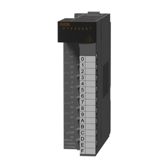
2 INPUT MODULE SPECIFICATIONS MELSEC-Q 2.2 QX28 AC Input Module Type AC Input Module Specifications QX28 Appearance Number of input points 8 points Isolation method Photocoupler Rated input voltage, frequency 100-240VAC (+10/-15%) 50/60Hz (±3Hz) (distortion factor within 5%) QX28 Approx. 17mA (200VAC, 60Hz), approx. 14mA (200VAC, 50Hz) 0 1 2 3 4 5 6 7 Rated input current Approx. -
Page 26: Qx40 Dc Input Module (Positive Common Type)
2 INPUT MODULE SPECIFICATIONS MELSEC-Q 2.3 QX40 DC Input Module (Positive Common Type) Type DC Input Module (Positive Common Type) Specifications QX40 Appearance Number of input points 16 points Isolation method Photocoupler Rated input voltage 24VDC (+20/-15%, ripple ratio within 5%) QX40 Rated input current Approx. -
Page 27: Qx40-S1 Dc Input Module (Positive Common Type)
2 INPUT MODULE SPECIFICATIONS MELSEC-Q 2.4 QX40-S1 DC Input Module (Positive Common Type) Type DC Input Module (Positive Common Type) Specifications QX40-S1 Appearance Number of input points 16 points Isolation method Photocoupler Rated input voltage 24VDC (+20/-15%, ripple ratio within 5%) Rated input current Approx. -
Page 28: Qx41 Dc Input Module (Positive Common Type)
2 INPUT MODULE SPECIFICATIONS MELSEC-Q 2.5 QX41 DC Input Module (Positive Common Type) Type DC Input Module (Positive Common Type) Specifications QX41 Appearance Number of input points 32 points Isolation method Photocoupler Rated input voltage 24VDC (+20/-15%, ripple ratio within 5%) QX41 Rated input current Approx. -
Page 29: Qx41-S1 Dc Input Module (Positive Common Type)
2 INPUT MODULE SPECIFICATIONS MELSEC-Q 2.6 QX41-S1 DC Input Module (Positive Common Type) Type DC Input Module (Positive Common Type) Specifications QX41-S1 Appearance Number of input points 32 points Isolation method Photocoupler Rated input voltage 24VDC (+20/-15%, ripple ratio within 5%) Rated input current Approx. - Page 30 2 INPUT MODULE SPECIFICATIONS MELSEC-Q Derating Chart Pin-Outs Pin No. Signal No. Pin No. Signal No. 28.8VDC ratio 50 55 Ambient temperature External Connections Internal circuit Vacant Vacant Module front view Vacant Vacant Vacant 24VDC Vacant 2 - 7 2 - 7...
-
Page 31: Qx42 Dc Input Module (Positive Common Type)
2 INPUT MODULE SPECIFICATIONS MELSEC-Q 2.7 QX42 DC Input Module (Positive Common Type) Type DC Input Module (Positive Common Type) Specifications QX42 Appearance Number of input points 64 points Isolation method Photocoupler QX42 Rated input voltage 24VDC (+20/-15%, ripple ratio within 5%) 0 1 2 3 4 5 6 7 8 9 A B C D E F Rated input current... -
Page 32: Qx42-S1 Dc Input Module (Positive Common Type)
2 INPUT MODULE SPECIFICATIONS MELSEC-Q 2.8 QX42-S1 DC Input Module (Positive Common Type) Type DC Input Module (Positive Common Type) Specifications QX42-S1 Appearance Number of input points 64 points Isolation method Photocoupler Rated input voltage 24VDC (+20/-15%, ripple ratio within 5%) Rated input current Approx. - Page 33 2 INPUT MODULE SPECIFICATIONS MELSEC-Q Sig- Sig- Sig- Sig- Derating Chart Pin-Outs 1B20 1A20 2B20 2A20 1B19 1A19 2B19 2A19 1B18 1A18 2B18 2A18 1B17 1A17 2B17 2A17 ratio 24VDC 1B16 1A16 2B16 2A16 26.4VDC 1B15 1A15 2B15 2A15 28.8VDC 1B14 1A14 2B14...
-
Page 34: Qx70 Dc Input Module (Positive Common/Negative Common Shared Type)
2 INPUT MODULE SPECIFICATIONS MELSEC-Q 2.9 QX70 DC Input Module (Positive Common/Negative Common Shared Type) Type DC Input Module (Positive Common/Negative Common Shared Type) Specifications QX70 Appearance Number of input points 16 points Insulation method Photocoupler 5VDC 12VDC Rated input voltage (+20/-15%, ripple ratio within 5%) (+20/-15%, ripple ratio within 5%) QX70... -
Page 35: Qx71 Dc Input Module (Positive Common/Negative Common Shared Type)
2 INPUT MODULE SPECIFICATIONS MELSEC-Q 2.10 QX71 DC Input Module (Positive Common/Negative Common Shared Type) Type DC Input Module (Positive Common/Negative Common Shared Type) Specifications QX71 Appearance Number of input points 32 points Insulation method Photocoupler 5VDC 12VDC Rated input voltage (+20/-15%, ripple ratio within 5%) (+20/-15%, ripple ratio within 5%) QX71... -
Page 36: Qx72 Dc Input Module (Positive Common/Negative Common Shared Type)
2 INPUT MODULE SPECIFICATIONS MELSEC-Q 2.11 QX72 DC Input Module (Positive Common/Negative Common Shared Type) Type DC Input Module (Positive Common/Negative Common Shared Type) Specifications QX72 Appearance Number of input points 64 points Insulation method Photocoupler 5VDC 12VDC QX72 Rated input voltage (+20/-15%, ripple ratio within 0 1 2 3 4 5 6 7 (+20/-15%, ripple ratio within 5%) -
Page 37: Qx80 Dc Input Module (Negative Common Type)
2 INPUT MODULE SPECIFICATIONS MELSEC-Q 2.12 QX80 DC Input Module (Negative Common Type) Type DC Input Module (Negative Common Type) Specifications QX80 Appearance Number of input points 16 points Isolation method Photocoupler Rated input voltage 24VDC (+20/-15%, ripple ratio within 5%) QX80 Rated input current Approx. -
Page 38: Qx81 Dc Input Module (Negative Common Type)
2 INPUT MODULE SPECIFICATIONS MELSEC-Q 2.13 QX81 DC Input Module (Negative Common Type) Type DC Input Module (Negative Common Type) Specifications QX81 Appearance Number of input points 32 points Isolation method Photocoupler Rated input voltage 24VDC (+20/-15%, ripple ratio within 5%) QX81 Rated input current Approx. -
Page 39: Qx82 Dc Input Module (Negative Common Type)
2 INPUT MODULE SPECIFICATIONS MELSEC-Q 2.14 QX82 DC Input Module (Negative Common Type) Type DC Input Module (Negative Common Type) Specifications QX82 Appearance Number of input points 64 points Isolation method Photocoupler QX82 Rated input voltage 24VDC (+20/-15%, ripple ratio within 5%) 0 1 2 3 4 5 6 7 8 9 A B C D E F Rated input current... -
Page 40: Qx82-S1 Dc Input Module (Negative Common Type)
2 INPUT MODULE SPECIFICATIONS MELSEC-Q 2.15 QX82-S1 DC Input Module (Negative Common Type) Type DC Input Module (Negative Common Type) Specifications QX82-S1 Appearance Number of input points 64 points Isolation method Photocoupler Rated input voltage 24VDC (+20/-15%, ripple ratio within 5%) Rated input current Approx. - Page 41 2 INPUT MODULE SPECIFICATIONS MELSEC-Q Sig- Sig- Sig- Sig- Derating Chart Pin-Outs 1B20 1A20 2B20 2A20 1B19 1A19 2B19 2A19 1B18 1A18 2B18 2A18 1B17 1A17 2B17 2A17 ratio 24VDC 1B16 1A16 2B16 2A16 26.4VDC 1B15 1A15 2B15 2A15 28.8VDC 1B14 1A14 2B14...
-
Page 42: Output Module Specifications
3 OUTPUT MODULE SPECIFICATIONS MELSEC-Q 3. OUTPUT MODULE SPECIFICATIONS 3.1 QY10 Contact Output Module Type Contact Output Module Specifications QY10 Appearance Number of output points 16 points Isolation method Relay Rated switching voltage, 24VDC 2A (resistive load) /point, 8A/common current 240VAC 2A (cos Minimum switching load 5VDC 1mA... - Page 43 3 OUTPUT MODULE SPECIFICATIONS MELSEC-Q 3.2 QY18A Contact Output Module (All Independent) Type Contact Output Module (All points Independent) Specifications QY18A Appearance Number of output points 8 points Isolation method Relay isolation Rated switching 24VDC 2A (resistive load) point voltage/current 240VAC 2A (cos Min.
-
Page 44: Qy22 Triac Output Module
3 OUTPUT MODULE SPECIFICATIONS MELSEC-Q 3.3 QY22 TRIAC Output Module Type TRIAC Output Module Specifications QY22 Appearance Number of output points 16 points Isolation method Photocoupler Rated load voltage 100-240VDC (+20/-15%) Maximum load current 0.6A/point, 4.8A/common Minimum load voltage/current 24VAC 100mA, 100VAC 25mA, 240VAC 25mA QY22 0 1 2 3 4 5 6 7 Maximum rush current... -
Page 45: Qy40P Transistor Output Module (Sink Type)
3 OUTPUT MODULE SPECIFICATIONS MELSEC-Q 3.4 QY40P Transistor Output Module (Sink Type) Type Transistor Output Module (Sink Type) Specifications QY40P Appearance Number of output points 16 points Isolation method Photocoupler Rated load voltage 12-24VDC (+20/-15%) Maximum load current 0.1A/point, 1.6A/common Maximum inrush current 0.7A, 10ms or less Leakage current at OFF... -
Page 46: Qy41P Transistor Output Module (Sink Type)
3 OUTPUT MODULE SPECIFICATIONS MELSEC-Q 3.5 QY41P Transistor Output Module (Sink Type) Type Transistor Output Module (Sink Type) Specifications QY41P Appearance Number of output points 32 points Isolation method Photocoupler Rated load voltage 12-24VDC (+20/-15%) Maximum load current 0.1A/point, 2A/common Maximum inrush current 0.7A, 10ms or less Leakage current at OFF... -
Page 47: Qy42P Transistor Output Module (Sink Type)
3 OUTPUT MODULE SPECIFICATIONS MELSEC-Q 3.6 QY42P Transistor Output Module (Sink Type) Type Transistor Output Module (Sink Type) Specifications QY42P Appearance Number of output points 64 points Isolation method Photocoupler Rated load voltage 12-24VDC (+20/-15%) Maximum load current 0.1A/point, 2A/common Maximum inrush current 0.7A, 10ms or less QY42P... -
Page 48: Qy50 Transistor Output Module (Sink Type)
3 OUTPUT MODULE SPECIFICATIONS MELSEC-Q 3.7 QY50 Transistor Output Module (Sink Type) Type Transistor Output Module (Sink Type) Specifications QY50 Appearance Number of output points 16 points Isolation method Photocoupler Rated load voltage 12-24VDC (+20/-15%) Maximum load current 0.5A/point, 4A/common Maximum inrush current 4A, 10ms or less QY50... -
Page 49: Qy68 Transistor Output Module (All Points Independent, Sink/Source Type)
3 OUTPUT MODULE SPECIFICATIONS MELSEC-Q 3.8 QY68A Transistor Output Module (All Points Independent, Sink/Source Type) Type Transistor Output Module (All Points Independent, Sink/Source Type) Specifications QY68A Appearance Number of output points 8 points Isolation method Photocoupler Rated load voltage 5-24VDC (+20/-10%) Maximum load current 2A/point, 8A/unit Maximum inrush current... -
Page 50: Qy70 Transistor Output Module (Sink Type)
3 OUTPUT MODULE SPECIFICATIONS MELSEC-Q 3.9 QY70 Transistor Output Module (Sink Type) Type Transistor Output Module (Sink Type) Specifications QY70 Appearance Number of output points 16 points Isolation method Photocoupler Rated load voltage 5/12VDC (+25/-10%) Maximum load current 16mA/point, 256mA/common Maximum inrush current 40mA, 10ms or less QY70... -
Page 51: Qy71 Transistor Output Module (Sink Type)
3 OUTPUT MODULE SPECIFICATIONS MELSEC-Q 3.10 QY71 Transistor Output Module (Sink Type) Type Transistor Output Module (Sink Type) Specifications QY71 Appearance Number of output points 32 points Isolation method Photocoupler Rated load voltage 5/12VDC (+25/-10%) Maximum load current 16mA/point, 512mA/common QY71 0 1 2 3 4 5 6 7 Maximum inrush current... -
Page 52: Qy80 Transistor Output Module (Source Type)
3 OUTPUT MODULE SPECIFICATIONS MELSEC-Q 3.11 QY80 Transistor Output Module (Source Type) Type Transistor Output Module (Source Type) Specifications QY80 Appearance Number of output points 16 points Isolation method Photocoupler Rated load voltage 12-24VDC (+20/-15%) Maximum load current 0.5A/point, 4A/common Maximum inrush current 4A, 10ms or less QY80... -
Page 53: Qy81P Transistor Output Module (Source Type)
3 OUTPUT MODULE SPECIFICATIONS MELSEC-Q 3.12 QY81P Transistor Output Module (Source Type) Type Transistor Output Module (Source Type) Specifications QY81P Appearance Number of output points 32 points Isolation method Photocoupler Rated load voltage 12-24VDC (+20/-15%) Maximum load current 0.1A/point, 2A/common Maximum inrush current 0.7A, 10ms or less Leakage current at OFF... - Page 54 3 OUTPUT MODULE SPECIFICATIONS MELSEC-Q MEMO 3 - 13 3 - 13...
-
Page 55: Input/Output Conposite Module
4 INPUT/OUTPUT CONPOSITE MODULE MELSEC-Q 4. INPUT/OUTPUT CONPOSITE MODULE 4.1 QH42P I/O Module (1) DC Input Specification (Positive Common Type) Type QH42P I/O Module (Input Specification) Specifications Number of input points 32 points Insulation method Photocoupler Rated input voltage 24VDC (+20/-15%, ripple ratio within 5%) Rated input current Approx. - Page 56 4 INPUT/OUTPUT CONPOSITE MODULE MELSEC-Q (2) Transistor Output Specification (Sink Type) Type QH42P I/O Module (Output Specification) Appearance Specifications Number of output points 32 points QH42P Insulation method Photocoupler 0 1 2 3 4 5 6 7 8 9 A B C D E F Rated load voltage 12-24VDC (+20/-15%) 0 1 2 3 4 5 6 7...
-
Page 57: Qx48Y57 I/O Module
4 INPUT/OUTPUT CONPOSITE MODULE MELSEC-Q 4.2 QX48Y57 I/O Module (1) DC Input Specification (Positive Common Type) Type QX48Y57 I/O Module (Input Specification) Appearance Specifications Number of input points 8 points Insulation method Photocoupler Rated input voltage 24VDC (+20/-15%, ripple ratio within 5%) Rated input current Approx. - Page 58 4 INPUT/OUTPUT CONPOSITE MODULE MELSEC-Q (2) Transistor Output Specifications (Sink Type) Type QX48Y57 I/O Module (Output Specification) Specifications Number of output points 7 points Insulation method Photocoupler Rated load voltage 12-24VDC (+20/-15%) Max. load current 0.5A/point, 2A/common Max. rush current 4A/10ms or less Leakage current at OFF 0.1mA or lower...
-
Page 59: Interrupt Module
5 INTERRUPT MODULE MELSEC-Q 5. INTERRUPT MODULE 5.1 QI60 Interrupt Module Type Interrupt Module Specifications QI60 Appearance Number of input points 16 points Isolation method Photocoupler Rated input voltage 24VDC (+20/-15%, ripple ratio within 5%) Rated input current Approx. 6mA QI60 Input derating 0 1 2 3 4 5 6 7... - Page 60 5 INTERRUPT MODULE MELSEC-Q MEMO 5 - 2 5 - 2...
-
Page 61: Blank Cover Module
6 BLANK COVER MODULE MELSEC-Q 6. BLANK COVER MODULE This chapter provides the specifications of the blank cover module used to protect the vacant slot (between I/O modules) of the base module from dust. Table 6.1 Blank Cover Module Specifications Type QG60 Item... - Page 62 6 BLANK COVER MODULE MELSEC-Q MEMO 6 - 2 6 - 2...
-
Page 63: Connectors
7 CONNECTORS MELSEC-Q 7. CONNECTORS The 40-pin connectors and 37-pin D-sub connectors used with the input and output modules are to be user-prepared. The following tables list the connector types and applicable models, and introduce crimp-contact and pressure-displacement tools. (1) 40-pin connectors (a) 40-pin connectors Type Model Name... - Page 64 7 CONNECTORS MELSEC-Q (b) 37-pin D-sub connector crimp-contact and pressure- displacement tools Type Model Name Contact Crimp-contact tool 90312-1 AMP Incorporated Americas: Worldwide Headquarters of 91257-1 (die set) AMP Incorporated Harrisburg, PA, U.S.A. Phone: (717) 564-0100 Fax: (717) 986-7813 Far East: AMP Singapore Pte.
-
Page 65: Specifications Of Connector/Terminal Block Convertor Modules
8 SPECIFICATIONS OF CONNECTOR/TERMINAL BLOCK CONVERTOR MODULES MELSEC-Q 8. SPECIFICATIONS OF CONNECTOR/TERMINAL BLOCK CONVERTOR MODULES 8.1 Specifications of Connector/Terminal Block Convertor Modules This chapter explains the specifications of connector/terminal block convertor modules. (1) Connector/Terminal Block Convertor Module Specifications Type Details Weight Applicable Models For positive common type input... - Page 66 8 SPECIFICATIONS OF CONNECTOR/TERMINAL BLOCK CONVERTOR MODULES MELSEC-Q IMPORTANT (1) The number of connectable I/O points is 32 for all connector/terminal block convertor modules. Two connector/terminal block convertor modules and two cables for connector/terminal block convertor modules are required for 64-point I/O modules.
-
Page 67: Connector/Terminal Block Convertor Module Connection Diagrams
8 SPECIFICATIONS OF CONNECTOR/TERMINAL BLOCK CONVERTOR MODULES MELSEC-Q 8.2 Connector/Terminal Block Convertor Module Connection Diagrams 8.2.1 A6TBXY36 (1) When connecting an input module Input Module (2) When connecting an output module (a) Sink Type Load Output Module (b) Source Type Load Output Module... -
Page 68: A6Tbxy54
8 SPECIFICATIONS OF CONNECTOR/TERMINAL BLOCK CONVERTOR MODULES MELSEC-Q 8.2.2 A6TBXY54 (1) When connecting an input 2-wire type sensor module Input Module (2) When connecting an output module (a) Sink Type Load Output Module (b) Source Type Load Output Module 8 - 4 8 - 4... -
Page 69: A6Tbx70
8 SPECIFICATIONS OF CONNECTOR/TERMINAL BLOCK CONVERTOR MODULES MELSEC-Q 8.2.3 A6TBX70 3-wire type sensor 2-wire type sensor Input Module 8.2.4 A6TBX36-E Input Module 8 - 5 8 - 5... -
Page 70: A6Tby36-E
8 SPECIFICATIONS OF CONNECTOR/TERMINAL BLOCK CONVERTOR MODULES MELSEC-Q 8.2.5 A6TBY36-E Load Output Module 8.2.6 A6TBX54-E 2-wire type sensor Input Module 8 - 6 8 - 6... -
Page 71: A6Tby54-E
8 SPECIFICATIONS OF CONNECTOR/TERMINAL BLOCK CONVERTOR MODULES MELSEC-Q 8.2.7 A6TBY54-E Load Output Module 8.2.8 A6TBX70-E 3-wire type sensor 2-wire type sensor Input Module 8 - 7 8 - 7... -
Page 72: Spring Clamp Terminal Block
Since the Q6TE-18S uses a spring clamp it does not require screw tightening, which greatly reduces the number of wiring procedures. Compatible Models The QT6E-18S can be used with the following models: Model type Model name QX10 QX28 QX40 QX40-S1 QX70 QX80... - Page 73 9 SPRING CLAMP TERMINAL BLOCK MELSEC-Q (b) Installation of Q6TE-18S ! Attach the Q6TE-18S to the module. ! Tighten the terminal block mounting screws within the specified torque range. Module Q6TE-18S Terminal block mounting screw (c) Cable Installation Insert the tool into the square shaped hole, which corresponds to the terminal you wish to use.
- Page 74 MELSEC-Q 10. NAMES OF MODULE PARTS This chapter explains the names of the I/O module parts. Terminal block connector 40-pin connector QX10 QX41 QX42 0 1 2 3 4 5 6 7 0 1 2 3 4 5 6 7...
- Page 75 10 NAMES OF MODULE PARTS MELSEC-Q 37-pin D-sub connector QX81 0 1 2 3 4 5 6 7 8 9 A B C D E F 0 1 2 3 4 5 6 7 8 9 A B C D E F QX81 24VDC Name...
- Page 76 10 NAMES OF MODULE PARTS MELSEC-Q A6TB A6TB Name Description Panel mounting hole Used for mounting to panel (for M4 screw). Terminal block Used to connect power and signal wires. Designed for 32-point module and used to connect power and 40-pin connector I/O signal wires.
-
Page 77: Q6Te-18S
10 NAMES OF MODULE PARTS MELSEC-Q A6TBX70 Name Description Panel mounting hole Used for mounting to panel (for M4 screw). Terminal block Used to connect power and signal wires. Designed for 32-point module and used to connect power and 40-pin connector I/O signal wires. -
Page 78: I/O Module Troubleshooting
11 I/O MODULE TROUBLESHOOTING MELSEC-Q 11. I/O MODULE TROUBLESHOOTING This chapter explains possible problems with I/O circuits and their corrective actions. 11.1 Input Circuit Troubleshooting This section describes possible problems with input circuits and their corrective actions. Table 11.1 Input Circuit Problems and Corrective Actions Condition Cause Corrective Action... - Page 79 11 I/O MODULE TROUBLESHOOTING MELSEC-Q Table 11.1 Input Circuit Problems and Corrective Actions (Continued) Condition Cause Corrective Action Input signal • Drive by switch with LED indicator. • Connect a register which will make the voltage DC input does not between the input module terminal and (Positive common) turn OFF.
- Page 80 11 I/O MODULE TROUBLESHOOTING MELSEC-Q (1) The 1.7mA OFF current of the QX40 is not satisfied. Hence, connect a resistor as shown below. QX40 Iz=1.7mA 2.3mA Input impedance 5.6K 3.6K 24VDC (2) Calculate the resistor value R as indicated below. To satisfy the 1.7mA OFF current of the QX40, the resistor R to be connected may be the one where 2.3mA or more will flow.
-
Page 81: Output Circuit Troubleshooting
11 I/O MODULE TROUBLESHOOTING MELSEC-Q 11.2 Output Circuit Troubleshooting This section describes possible problems with output circuits and their corrective actions. Table 11.2 output Circuit Problems and Corrective Actions Condition Cause Corrective Action When the • Load is half-wave rectified inside (in some •... -
Page 82: Appendices
APPENDICES Appendix 1 External Dimensional Drawings Appendix 1.1 I/O modules (1) Terminal block connector type (a) Other than QY22 APP. QX10 0 1 2 3 4 5 6 7 8 9 A B C D E F 100VAC 8mA60Hz 7mA50Hz 2 (0.08) - Page 83 APPENDICES MELSEC-Q (2) 40-pin connector type (a) 32-point I/O module QX41 0 1 2 3 4 5 6 7 8 9 A B C D E F 0 1 2 3 4 5 6 7 APP. 8 9 A B C D E F QX41 24VDC 2 (0.08)
- Page 84 APPENDICES MELSEC-Q (3) 37-pin D-sub connector type 32-point I/O module QX81 0 1 2 3 4 5 6 7 8 9 A B C D E F 0 1 2 3 4 5 6 7 8 9 A B C D E F QX81 24VDC 2 (0.08)
-
Page 85: Appendix 1.2 Connectors, Connector/Terminal Block Converter Modules
APPENDICES MELSEC-Q Appendix 1.2 Connectors, connector/terminal block converter modules (1) 40-pin connectors (a) A6CON1 soldering type, A6CON2 crimp-contact type 40-pin connector 14 (0.55) or less 46 (1.81) 72.72 (2.87) (b) A6CON3 pressure-displacement type 40-pin connector 69.48 (2.74) 8.25 (0.33) Flat cable arrangement is in the following sequence. - Page 86 APPENDICES MELSEC-Q (2) 37-pin D-sub connectors (a) A6CON1E soldering type, A6CON2E crimp-contact type 37-pin D-sub connector 20.3 (0.8) 69.5 (2.74) (b) A6CON3E pressure-displacement type 37-pin D-sub connector 69.4 (2.73) 12.6 (0.5) 3.4 (0.13) 5.9 (0.23) Unit: mm (inch) App - 5 App - 5...
- Page 87 APPENDICES MELSEC-Q (3) A6TB connector/terminal block converter module 2 (0.08)- 4.5 (0.18) mounting hole (M4 25) 89.6 (3.53) 5.5 (0.22) 48 (1.89) 120 (4.73) 52 (2.05) (4) A6TB connector/terminal block converter module 2 (0.08)- 4.5 (0.18) mounting hole (M4 25) 124.6 (4.91) 5.5 (0.22) 48 (1.89)
-
Page 88: Appendix 1.3 Spring Clamp Terminal Block
APPENDICES MELSEC-Q Appendix 1.3 Spring Clamp Terminal Block (1) Q6TE-18S Installed on a module (Example: QX10) Q6TE -18S (1.06) (0.91) (3.54) Unit: mm(inch) *: The depth of the module installed with a Q6TE-18S is equivalent with the factory default dimensions for that module. -
Page 89: Appendix 2 Compatibility With Melsec-Ans Series I/O Modules
Note that the MELSEC-Q series I/O modules and MELSEC-AnS series I/O modules are different in external terminal block configuration. Differences in terminal block configuration are indicated below. (1) Input modules Terminal Block A1SX10, A1SX40, QX10, QX40 QX80 Number A1SX80 TB10 TB11 •... - Page 90 APPENDICES MELSEC-Q Terminal Terminal Block QY50 A1SY50 Block QY80 A1SY80 Number Number 12/24VDC COM1 TB10 COM1 TB10 TB11 TB11 • • • • • • • • • • • • • • • • • • TB16 TB16 TB17 12/24VDC TB17 TB18...
- Page 91 WARRANTY Please confirm the following product warranty details before starting use. 1. Gratis Warranty Term and Gratis Warranty Range If any faults or defects (hereinafter "Failure") found to be the responsibility of Mitsubishi occurs during use of the product within the gratis warranty term, the product shall be repaired at no cost via the dealer or Mitsubishi Service Company. Note that if repairs are required at a site overseas, on a detached island or remote place, expenses to dispatch an engineer shall be charged for.
- Page 92 MITSUBISHI ELECTRIC HEADQUARTERS EUROPEAN REPRESENTATIVES EUROPEAN REPRESENTATIVES EUROPEAN REPRESENTATIVES MITSUBISHI ELECTRIC EUROPE GEVA AUSTRIA UAB UTU POWEL LITHUANIA Avtomatika Sever Ltd. RUSSIA EUROPE B.V. Wiener Straße 89 Savanoriu pr. 187 Lva Tolstogo St. 7, Off. 311 German Branch AT-2500 Baden...