Skyjack SJIII 3220 Operating & Maintenance Manual
The conventionals
Hide thumbs
Also See for SJIII 3220:
- Service manual (94 pages) ,
- Operating manual (108 pages) ,
- Operating manual (104 pages)
Table of Contents
Advertisement
Quick Links
OPERATING
MAINTENANCE
& PARTS
MANUAL
For Service in North America and Asia please call .....................................
SKYJACK Inc. Service Center 3451 Swenson Ave., St. Charles, IL 60174 .....................
For Parts in North America and Asia please call .........................................
SKYJACK Inc. Parts Center 990 Vernon Rd., Wathina, KS 66090 ..................................
For Parts & Service in Canada please call ...................................................
SKYJACK Inc. 55 Campbell Rd., Guelph, Ontario, Canada N1H 1B9 ..............................
For Parts & Service in Europe please call ...............................................
TM
SKYJACK Europe Communicatieweg 29, 3641 SG Mijdrecht Netherlands ................
Printed in Canada
117128AF
TM
800 275-9522
FAX 630 262-0006
800 965-4626
FAX 888 782-4825
800 265-2738
FAX 519 837-3883
31 297 255 526
FAX 31 297 256 948
Complete Revision Nov-2013
Advertisement
Table of Contents
Troubleshooting

Related Manuals for Skyjack SJIII 3220


Summary of Contents for Skyjack SJIII 3220
- Page 1 800 275-9522 For Service in North America and Asia please call ........FAX 630 262-0006 SKYJACK Inc. Service Center 3451 Swenson Ave., St. Charles, IL 60174 ..... 800 965-4626 For Parts in North America and Asia please call ......... FAX 888 782-4825 SKYJACK Inc.
- Page 2 DO NOT OPERATE THIS EQUIPMENT WITHOUT PROPER AUTHORIZATION, TRAINING AND UNDERSTANDING OF THE OPERATION OF BOTH STANDARD AND OPTIONAL EQUIPMENT. DO NOT USE A WORK PLATFORM THAT HAS OPTIONS, ALTERATIONS OR MODIFICATIONS NOT APPROVED BY SKYJACK. SERIAL NUMBER BREAKDOWN MANUAL PART...
-
Page 3: Table Of Contents
TABLE OF CONTENTS SUBJECT - SECTION, PARAGRAPH PAGE NO. SECTION 1 INTRODUCTION PURPOSE OF EQUIPMENT ..................1 USE OF EQUIPMENT ....................1 WARNINGS ........................1 DESCRIPTION ......................1 SAFETY PANEL AND WARNING LABELS ..............2 SPECIFICATIONS AND FEATURES ................4 WORK PLATFORM MAJOR COMPONENT IDENTIFICATION ........ -
Page 4: Warnings
You, as a careful operator, are the best insurance against an accident. Therefore, proper usage of this work platform is mandatory. The following pages of this manual should be read and understood completely before operating the work platform. Any modifications from the original design are strictly forbidden without written permission from SKYJACK, Inc. DANGER VOLTAGE RANGE... - Page 5 SKYJACK, Inc. warrants each new SJIII Series work platform to be free of defective parts and workmanship for the first 12 months. Any defective part will be replaced or repaired by your local SKYJACK dealer at no charge for parts or labor. Refer to Warranty Statement for extentions or exclusions.
- Page 6 Skyjack within 15 days from the time of billing. When specified territory, limited to a maximum of four (4) work platforms are put into stock, the warranty period hours.
-
Page 7: Description
PURPOSE OF EQUIPMENT LIFTING MECHANISM - The lifting mechanism is The SKYJACK SJIII Series Work Platform is designed constructed from steel tubing making up a scissor- to transport and raise personnel, tools and materials type assembly. The scissor-type assembly is raised 1 1 1 1 1 to overhead work areas. - Page 8 DANGER TIP-OVER HAZARDS DO NOT RAISE PLATFORM IN WINDY OR GUSTY CONDITIONS. DO NOT DRIVE NEAR DROP-OFFS, HOLES, ELECTROCUTION HAZARD OPEN ELEVATOR SHAFTS, AND LOADING DOCKS. THIS MACHINE IS NOT INSULATED. MAINTAIN SAFE CLEARANCES FROM ELECTRICAL POWER LINES AND APPARATUS. YOU MUST ALLOW FOR PLATFORM SWAY, ROCK, OR SAG.
- Page 9 DO NOT exert excessive side forces on platform while elevated. DO NOT overload, the lift relief valve does not protect against overloading when the platform is elevated. DO NOT alter or disable limit switches or other safety devices. DO NOT exceed the rated capacity of your scissorlift and make sure the load is evenly distributed on the platform.
- Page 10 SECTION 1, Page 4 SJIII Series - The CONVENTIONALS Complete Revision 99-05-01...
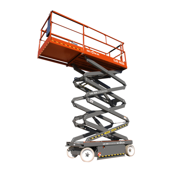
- Page 11 WORK PLATFORM MAJOR COMPONENT IDENTIFICATION OPERATOR’S CONTROL BOX EXTENSION PLATFORM MAIN PLATFORM LIFTING MECHANISM BATTERY TRAY HYDRAULIC/ ELECTRIC TRAY POTHOLE BASE PROTECTION DEVICE Figure 1-2. SJIII Series Work Platform (Model 3220 shown) SJIII Series - The CONVENTIONALS SECTION 1, Page 5 Complete Revision 99-05-01...
- Page 12 SECTION 2 OPERATION 2- HOURMETER - Activated when the pump/motor OPERATOR QUALIFICATIONS runs, this gauge records work platform operating time. Only trained and authorized persons should use this work platform. Safe use of this work platform requires 3- 15 AMP CIRCUIT BREAKER RESETS - In the the operator to understand the limitations and warnings, event of a power overload or positive circuit operating procedures and operator’s responsibility for...
- Page 13 Base Controls - Hydraulic Base Control Box (CE) Emergency Lowering System Figure 2-3. Base Control Box (CE) BASE CONTROL BOX (CE) - This metal control station is mounted on the rear of the base. It contains the following controls: 1- PLATFORM UP/DOWN TOGGLE SWITCH - To raise the platform, select “BASE”...
- Page 14 Free-Wheeling Valve Base Controls - Hydraulic/Manual Parking Brake Figure 2-5. Free-Wheeling Valve 1- FREE-WHEELING VALVE - The free-wheeling valve is located at the rear of the machine. Turning the Figure 2-6. Parking Brake valve knob counterclockwise to a fully opened posi- tion allows fluid to flow through the wheel motors, 1- PARKING BRAKE - The parking brakes are de- thus providing “free-wheeling”...
- Page 15 Safety Bar and Pothole Protection Device 2- POTHOLE PROTECTION DEVICE - This device consists of a mechanically actuated steel weldments, located under the hydraulic/electric tray and battery tray, these weldments will automatically rotate for reduced ground clearance when elevating the platform.
- Page 16 Platform Controls 5- PROPORTIONAL CONTROLLER - A one-hand toggle-type lever to control proportional drive/lift Operator’s Control Box motion and steer motion. It is a “deadman” control which returns to neutral and locks when released. To drive forward, select “DRIVE” position with the Lift/ Off/Drive Select Toggle Switch, then lift the controller lock ring and push the controller handle forward to the desired speed.
- Page 17 Powered Extension Platform Control Box Fold-Down Guardrail System Figure 2-11. Fold-Down Guardrail System FOLD-DOWN GUARDRAIL SYSTEM - This system Figure 2-10. Powered Extension Platform Control when folded down, reduces the shut height of the work platform for travelling through standard doorways. POWERED EXTENSION PLATFORM CONTROL BOX 1- GUARDRAIL LOCKING PIN W/LANYARD - To This metal control station is mounted at the right front...
- Page 18 SET-UP PROCEDURE In the hydraulic/electric tray, check the hydraulic oil level (scissors MUST be fully lowered) in the tank. Level should be at or The following steps are normally required for equip- slightly above the top mark on the gauge. If ment being put into service for the first time.
-
Page 19: Operating Procedures Prestart Checks
Raise the platform to the maximum extension OPERATING PROCEDURES height. Prestart Checks NOTE Carefully read and completely understand Refer to Table 5-5. General Specifications (Section 5, ALL of SECTION 2, OPERATION in this Page 8) for raise and lowering times. manual and ALL warnings and instruction labels on the work platform. -
Page 20: Start And Operation
WARNING WARNING DO NOT OPERATE THIS EQUIPMENT If the machine does not drive when elevated, do not engage the drive controller. Lower the platform WITHOUT PROPER AUTHORIZATION AND immediately and ensure that there are no electrical TRAINING. DEATH OR SERIOUS INJURY cords and hoses with a diameter of more than 1/2”... -
Page 21: Battery Service And Charging Procedures
BATTERY SERVICE AND CHARGING Battery Charging Procedures(StandardMachines) PROCEDURES WARNING Battery Service EXPLOSION HAZARD WARNING Chargers can ignite flammable materials and vapors. EXPLOSION HAZARD DO NOT use near fuels, grain dust, solvents or other flammables Keep flames and sparks away. DO NOT smoke near batteries. - Page 22 BATTERY CHARGER OPERATION WARNING Bycan Charger DO NOT CHARGE BATTERIES IN HAZARDOUS AREA! THE EE-RATING OF THIS MACHINE DOES NOT INCLUDE THE CHARGING OF BATTERIES. Battery Charging Procedures (EE-RateMachines) Move the work platform to an area designated for battery charging. (Refer to NFPA 505* for charging set-up.) *NFPA 505 is a publication of: National Fire Protection Association, Inc.
- Page 23 MAC Charger the operator that the batteries are fully charged. If the “80% CHARGE” light continues to stay on after the charge cycle is complete, this indicates to the operator that the batteries are not capable of attain- ing a full charge. If the “INCOMPLETE”...
-
Page 24: Table Of Contents
SECTION 3 SYSTEM COMPONENT IDENTIFICATION AND SCHEMATICS TABLE OF CONTENTS ELECTRICAL SYSTEM FIGURE 3-1. CONTROL BOX DIAGRAM AND PARTS LIST (ANSI/SIA and CSA) Shown With Horn Option ........................ Page 3 FIGURE 3-2. CONTROL BOX DIAGRAM AND PARTS LIST (ANSI/SIA and CSA) Shown With All Options ........................ - Page 25 FIGURE 3-1. CONTROL BOX DIAGRAM AND PARTS LIST With Horn (ANSI/SIA and CSA) Units Description Skyjack Index Part No. Assy. 119642 CABLE ASSEMBLY, Control box (For components, Refer to SECTION 6, FIGURE 6-16, Pages 34 & 36) 103012 BLOCK, 12 Pole terminal...
- Page 26 FIGURE 3-2. CONTROL BOX DIAGRAM AND PARTS LIST With All Options (ANSI/SIA and CSA) Units Description Skyjack Index Part No. Assy. 119731 CABLE ASSEMBLY, Control box (For components, Refer to SECTION 6, FIGURE 6-16, Pages 34 & 36) 103012 BLOCK, 12 Pole terminal...
- Page 27 FIGURE 3-3. CONTROL BOX DIAGRAM AND PARTS LIST With Horn (CE) Units Description Skyjack Index Part No. Assy. 119731 CABLE ASSEMBLY, Control box (For components, Refer to SECTION 6, FIGURE 6-16, Pages 34 & 36) 103012 BLOCK, 12 Pole terminal (For components, Refer to SECTION 6, FIGURE 6-16, Pages 34 &...
- Page 28 FIGURE 3-4. CONTROL BOX DIAGRAM AND PARTS LIST With ALL OPTIONS (CE) Units Description Skyjack Index Part No. Assy. 119731 CABLE ASSEMBLY, Control box (For components, Refer to SECTION 6, FIGURE 6-16, Pages 34 & 36) 103012 BLOCK, 12 Pole terminal...
- Page 29 FIGURE 3-5. ELECTRICAL SYMBOL CHART WIRE CROSSING HOURMETER KEY SWITCH WIRES JOINED LIGHT FOOT SWITCH HYDRAULIC BATTERY TOGGLE SWITCH VALVE COIL PROPORTIONAL HYDRAULIC GROUND PUSH BUTTON VALVE COIL ELECTRIC FUSE ROTARY SWITCH MOTOR CIRCUIT HORN LIMIT SWITCH BREAKER BATTERY EMERGENCY CAM OPERATED CHARGE STOP BUTTON...
- Page 30 FIGURE 3-7. RELAY FUNCTION CHART SUPPLY (B+) (Common) CONTROL (B+) GROUND (B-) NORMALLY NORMALLY CLOSED OPEN CONTACT CONTACT RELAY NO. RELAY FUNCTION 13BCR LWS MODULE TIME DELAY CUTOUT (CE) 17CR TRANSFER RELAY 21CR PROPORTIONAL RELAY (Machines with no options) 21ACR PROPORTIONAL RELAY (Machines with options) 28CR TILT SWITCH RELAY...
- Page 31 FIGURE 3-8. ELECTRICAL SCHEMATIC PARTS LIST With Horn (ANSI/SIA and CSA) SERIAL NUMBERS 608118, 66287, 703453, 86734, 75498 or 82263 & BELOW Units Description Skyjack Ref. Part No. Assy B1-B4 BATTERY, 6 Volt (Interstate #U2200) (Models 3220, 4620 & 4626) BATTERY, 6 Volt (Interstate #U2500) (Models 4830, 4832, 6826 &...
- Page 32 Parts List FIGURE 3-8. ELECTRICAL SCHEMATIC With Horn (ANSI/SIA and CSA) SERIAL NUMBERS 608118, 66287, 703453, 86734, 75498 or 82263 & BELOW SJIII Series - The CONVENTIONALS 117128 SECTION 3, Page 11 Complete Revision 99-05-01...
- Page 33 Parts List FIGURE 3-8. ELECTRICAL SCHEMATIC WITH HORN (ANSI/SIA and CSA) 117128 SECTION 3, Page 12 SJIII Series - The CONVENTIONALS Complete Revision 99-05-01...
- Page 34 FIGURE 3-8. ELECTRICAL SCHEMATIC PARTS LIST With Horn (ANSI/SIA and CSA) Units Description Skyjack Ref. Part No. Assy B1-B4 BATTERY, 6 Volt (Interstate #U2200) (Models 3220, 4620 & 4626) BATTERY, 6 Volt (Interstate #U2500) (Models 4830, 4832, 6826 & 6832)
- Page 35 Parts List FIGURE 3-9. ELECTRICAL SCHEMATIC With All Options (ANSI/SIA and CSA) 117128 SECTION 3, Page 14 SJIII Series - The CONVENTIONALS Complete Revision 99-05-01...
- Page 36 FIGURE 3-9. ELECTRICAL SCHEMATIC PARTS LIST With All Options (ANSI/SIA and CSA) Units Description Skyjack Ref. Part No. Assy B1-B4 BATTERY, 6 Volt (Interstate #U2200) (Models 3220, 4620 & 4626) BATTERY, 6 Volt (Interstate #U2500) (Models 4830, 4832, 6826 & 6832)
- Page 37 FIGURE 3-10. ELECTRICAL SCHEMATIC PARTS LIST Models 3220, 4620, 4626, 4830 & 4832 With All Options (CE) Units Description Skyjack Ref. Part No. Assy B1-B4 BATTERY, 6 Volt (Trojan #T2200) (Models 3220, 4620 & 4626) BATTERY, 6 Volt (Trojan #J250) (Model 4830 & 4832)
- Page 38 Parts List FIGURE 3-10. ELECTRICAL SCHEMATIC MODELS 3220, 4620, 4626, 4830 & 4832 WITH ALL OPTIONS (CE) SJIII Series - The CONVENTIONALS 117128 SECTION 3, Page 17 Complete Revision 99-05-01...
- Page 39 Parts List FIGURE 3-11. ELECTRICAL SCHEMATIC MODELS 6826 AND 6832 WITH ALL OPTIONS (CE) 117128 SECTION 3, Page 18 SJIII Series - The CONVENTIONALS Complete Revision 99-05-01...
- Page 40 FIGURE 3-10. ELECTRICAL SCHEMATIC PARTS LIST Models 3220, 4620, 4626, 4830 & 4832 With All Options (CE) Units Description Skyjack Ref. Part No. Assy B1-B4 BATTERY, 6 Volt (Trojan #T2200) (Models 3220, 4620 & 4626) BATTERY, 6 Volt (Trojan #J250) (Model 4830 & 4832)
- Page 41 FIGURE 3-12. ELECTRICAL PANEL PARTS LIST - No Options (ANSI/SIA and CSA) SERIAL NUMBERS 608118, 66287, 703453, 86734, 75498 or 82263 & BELOW Units Description Skyjack Index Part No. Assy. 119348 LIMIT SWITCH ASSEMBLY, Pothole protection (Models 3220, 4620, 4626, 4830 & 4832)
- Page 42 Parts List FIGURE 3-12. ELECTRICAL PANEL DIAGRAM - No Options (ANSI/SIA and CSA) SERIAL NUMBERS 608118, 66287, 703453, 86734, 75498 or 82263 & BELOW SJIII Series - The CONVENTIONALS 117128 SECTION 3, Page 21 Complete Revision 99-05-01...
- Page 43 Parts List FIGURE 3-12. ELECTRICAL PANEL DIAGRAM - No Options (ANSI/SIA and CSA) 117128 SECTION 3, Page 22 SJIII Series - The CONVENTIONALS Complete Revision 99-05-01...
- Page 44 FIGURE 3-12. ELECTRICAL PANEL PARTS LIST - No Options (ANSI/SIA and CSA) Units Description Skyjack Index Part No. Assy. 119348 LIMIT SWITCH ASSEMBLY, Pothole protection (Models 3220, 4620, 4626, 4830 & 4832) 108589 RELAY, 24 Volt (tilt) 115313 RESISTOR, 25 Watt, 30 Ohm (Models 3220, 4620, 4626, 4830 & 4832) 120174 RESISTOR, 25 Watt, 20 Ohm (Models 6826 &...
- Page 45 FIGURE 3-13. ELECTRICAL PANEL PARTS LIST - All Options (ANSI/SIA and CSA) SERIAL NUMBERS 608118, 66287, 703453, 86734, 75498 or 82263 & BELOW Units Description Skyjack Index Part No. Assy. 119348 LIMIT SWITCH ASSEMBLY, Pothole protection (Models 3220, 4620, 4626, 4830 & 4832)
- Page 46 Parts List FIGURE 3-13. ELECTRICAL PANEL DIAGRAM - All Options (ANSI/SIA and CSA) SERIAL NUMBERS 608118, 66287, 703453, 86734, 75498 or 82263 & BELOW SJIII Series - The CONVENTIONALS 117128 SECTION 3, Page 25 Complete Revision 99-05-01...
- Page 47 Parts List FIGURE 3-13. ELECTRICAL PANEL DIAGRAM - All Options (ANSI/SIA and CSA) 117128 SECTION 3, Page 26 SJIII Series - The CONVENTIONALS Complete Revision 99-05-01...
- Page 48 FIGURE 3-13. ELECTRICAL PANEL PARTS LIST - All Options (ANSI/SIA and CSA) Units Description Skyjack Index Part No. Assy. 119348 LIMIT SWITCH ASSEMBLY, Pothole protection (Models 3220, 4620, 4626, 4830 & 4832) 103267 FLASHER, 24 Volt (optional) 108589 RELAY, 24 Volt (tilt) 115313 RESISTOR, 25 Watt, 30 Ohm (Models 3220, 4620, 4626, 4830 &...
- Page 49 FIGURE 3-14. ELECTRICAL PANEL PARTS LIST - All Options (CE) SERIAL NUMBERS 608118, 66287, 703453, 86734, 75498 or 82263 & BELOW Units Description Skyjack Ref. Part No. Assy 119348 LIMIT SWITCH ASSEMBLY, Pothole protection (Models 3220, 4620, 4626, 4830 & 4832)
- Page 50 Parts List FIGURE 3-14. ELECTRICAL PANEL DIAGRAM - All Options (CE) FIGURE 3-14. ELECTRICAL PANEL PARTS LIST - All Options (CE) SERIAL NUMBERS 608118, 66287, 703453, 86734, 75498 or 82263 & BELOW SJIII Series - The CONVENTIONALS 117128 SECTION 3, Page 29 Complete Revision 99-05-01...
- Page 51 Parts List FIGURE 3-14. ELECTRICAL PANEL PARTS LIST - All Options (CE) 117128 SECTION 3, Page 30 SJIII Series - The CONVENTIONALS Complete Revision 99-05-01...
- Page 52 FIGURE 3-14. ELECTRICAL PANEL PARTS LIST - All Options (CE) Units Description Skyjack Ref. Part No. Assy 119954 LIMIT SWITCH ASS’Y, 26 Ft. drive cutout (Models 4830, 4832 and 6832) 119348 LIMIT SWITCH ASS’Y, Pothole protection (Models 3220, 4620, 4626, 4830 & 4832)
- Page 53 FIGURE 3-15. BATTERY CHARGER SCHEMATIC - Motor Appliance #BA610 Units Description Index Skyjack Part No. Assy. 108592 BATTERY CHARGER ASSEMBLY, 24V40A, 120VAC, 60Hz 109102 • CAPACITOR 109108 • TRANSFORMER 115315 • RELAY, Charger cutout 120 VAC 115391 • PLUG, Charger cutout 115392 •...
- Page 54 FIGURE 3-16. BATTERY CHARGER SCHEMATIC PARTS LIST - Bycan #2440A and 2440E Units Description Index Skyjack Part No. Assy. 112255 BATTERY CHARGER ASSEMBLY, 24V40A, 220VAC, 60 Hz 113415 BATTERY CHARGER ASSEMBLY, 24V40A, 220VAC, 50-60 Hz 117162 • AMMETER, 50 Amp 117163 •...
- Page 55 FIGURE 3-20. HYDRAULIC SYMBOL CHART VARIABLE DISPLACEMENT SHUTTLE VALVE VELOCITY FUSE LINE CROSSING PUMP ACCUMULATOR, SINGLE ACTING LINE JOINED HAND PUMP GAS CHARGED CYLINDER HYDRAULIC TANK CUSHION DOUBLE ACTING RELIEF VALVE CYLINDER CYLINDER PRESSURE HYDRAULIC DOUBLE ACTING PRESSURE REDUCING VALVE FILTER WITH DOUBLE RODDED SWITCH...
- Page 56 FIGURE 3-21. HYDRAULIC SCHEMATIC PARTS LIST (Models 3220 & 4620) Description Units Skyjack Ref. Part No. Assy 103831 CYLINDER, Cushion 106260 CYLINDER, Lift 117044 CYLINDER, Steer 117648 CYLINDER, Brake 117928 CYLINDER, Powered extension platform 104133 VALVE, Counterbalance CMP1 115382 VALVE, Pressure compensator...
- Page 57 Parts List Parts List FIGURE 3-21. HYDRAULIC SCHEMATIC (Models 3220 & 4620) SJIII Series - The CONVENTIONALS 117128 SECTION 3, Page 39 Complete Revision 99-05-01...
- Page 58 Parts List Parts List FIGURE 3-22. HYDRAULIC SCHEMATIC (Model 4626) 117128 SECTION 3, Page 40 SJIII Series - The CONVENTIONALS Complete Revision 99-05-01...
- Page 59 FIGURE 3-22 . HYDRAULIC SCHEMATIC PARTS LIST (Model 4626) Description Units Skyjack Ref. Part No. Assy 103831 CYLINDER, Cushion 106265 CYLINDER, Lift 117044 CYLINDER, Steer 117648 CYLINDER, Brake 117928 CYLINDER, Powered extension platform 104133 VALVE, Counterbalance CMP1 115382 VALVE, Pressure compensator...
- Page 60 FIGURE 3-23. HYDRAULIC SCHEMATIC PARTS LIST (Model 4830 & 4832) Description Units Skyjack Ref. Part No. Assy 103831 CYLINDER, Cushion 119585 CYLINDER, Lift upper 119586 CYLINDER, Lift lower 117044 CYLINDER, Steer 117648 CYLINDER, Brake 104133 VALVE, Counterbalance CMP1 115382 VALVE, Pressure compensator...
- Page 61 Parts List FIGURE 3-23. HYDRAULIC SCHEMATIC (Model 4830 & 4832) SJIII Series - The CONVENTIONALS 117128 SECTION 3, Page 43 Complete Revision 99-05-01...
- Page 62 Parts List FIGURE 3-24. HYDRAULIC SCHEMATIC (Models 6826 & 6832) 117128 SECTION 3, Page 44 SJIII Series - The CONVENTIONALS Complete Revision 99-05-01...
- Page 63 FIGURE 3-24. HYDRAULIC SCHEMATIC PARTS LIST (Models 6826 & 6832) Units Description Skyjack Ref. Part No. Assy 103831 CYLINDER, Cushion 107083 CYLINDER, Lift (Model 6826) 110677 CYLINDER, Lift (Model 6832) 117670 CYLINDER, Steer 117648 CYLINDER, Brake 117969 CYLINDER, Powered extension platform (option)
- Page 64 FIGURE 3-25. HYDRAULIC MANIFOLD COMPONENT IDENTIFICATION 2H-18A 3H-18A DIFFERENTIAL PILOT VALVE VALVE 3H-18A-2 SPEED VALVE B REAR DRIVE MANIFOLD FLOW REAR DIVIDER/COMBINER DRIVE VALVE MANIFOLD FREE-WHEELING 2H-59B VALVE PROPORTIONAL VALVE 3H-18A-1 CHECK CHECK SPEED VALVE VALVE VALVE A 3H-14 LIFT VALVE PROPORTIONAL MANIFOLD...
- Page 65 SECTION 4 TROUBLESHOOTING INFORMATION The following pages contain a Table of Troubleshooting information for locating and correcting most service trouble which can develop. Careful inspection and accurate analysis of the systems listed in the Table of Troubleshooting Information will localize the trouble more quickly than any other method. This manual cannot cover all possible troubles and deficiencies that may occur.
- Page 66 TROUBLESHOOTING INFORMATION TROUBLE PROBABLE CAUSE REMEDY ELECTRICAL SYSTEM ALL CONTROLS 20. Loose or broken wire #59B from Relay 20. Check continuity. Replace if (21CR) to Proportional Valve Coil defective. INOPERATIVE (Cont.) (2H-59B). 21. Loose or broken wire #02 from Proportional Valve Coil (2H-59B) to 21.
- Page 67 TROUBLESHOOTING INFORMATION TROUBLE PROBABLE CAUSE REMEDY ELECTRICAL SYSTEM NO DOWN OR REVERSE 1. Loose or broken wire “A” from 1. Check continuity. Replace if ONLY FUNCTION FROM Proportional Controller (S7) to Lift/Drive defective. PLATFORM CONTROLS Switch (S5). 2. Lift/Drive Switch (S5) defective. 2.
- Page 68 TROUBLESHOOTING INFORMATION TROUBLE PROBABLE CAUSE REMEDY ELECTRICAL SYSTEM 7. Loose or broken wire # 13A from Down 7. Check continuity. Replace if NO DOWN FUNCTION Valve Coil (2H-13A) to Lift Cylinder defective. FROM PLATFORM OR Holding Valve (2H-13A-1) through (2H- BASE CONTROLS 13A-4).
- Page 69 TROUBLESHOOTING INFORMATION TROUBLE PROBABLE CAUSE REMEDY ELECTRICAL SYSTEM 1. Open Diode (D14E-2). PLATFORM LIFTS SLOW 1. Check diode. Replace e if defective. FROM PLATFORM CONTROLS AND BASE CONTROLS 1. Defective Relay (17CR). 1. Check relay. Replace if defective. STEER ONLY 2.
- Page 70 TROUBLESHOOTING INFORMATION TROUBLE PROBABLE CAUSE REMEDY ELECTRICAL SYSTEM RIGHT STEER 1. Defective Steer Right Switch (S72). 1. Check switch. Replace if defective. INOPERATIVE 2. Loose or broken wire #23 from Steer 2. Check continuity. Replace if (Machines without Right Switch (S72) to Lift/Drive Select defective.
- Page 71 TROUBLESHOOTING INFORMATION TROUBLE PROBABLE CAUSE REMEDY ELECTRICAL SYSTEM 1. Defective Left Steer Switch (S73). 1. Check switch. Replace if defective. LEFT STEER 2. Loose or broken wire #24 from Left 2. Check continuity. Replace if INOPERATIVE (Machines Steer Switch (S73) to Platform Terminal defective.
- Page 72 TROUBLESHOOTING INFORMATION TROUBLE PROBABLE CAUSE REMEDY ELECTRICAL SYSTEM 1. Loose or broken wire #15 from Lift/ 1. Check continuity. Replace if REVERSE DRIVE Drive Select Switch (S5) to Base defective. FUNCTION Terminal Block (TB-1). INOPERATIVE 2. Loose or broken wire #15 from Base 2.
- Page 73 TROUBLESHOOTING INFORMATION TROUBLE PROBABLE CAUSE REMEDY ELECTRICAL SYSTEM POWERED EXTENSION 1. Powered Platform Extend/Retract 1. Check switch. Replace if defective. Switch (S11) defective. PLATFORM WILL NOT 2. Loose or broken wire #26 from 2. Check continuity. Replace if EXTEND Powered Platform Extend/Retract defective.
- Page 74 TROUBLESHOOTING INFORMATION TROUBLE PROBABLE CAUSE REMEDY HYDRAULIC SYSTEM 1. Check valve. Replace if defective. ALL FUNCTIONS 1. Proportional Valve (2H-59B) defective INOPERATIVE or is sticking. 2. Check valve. Replace if defective. 2. Compensator Valve (CMP1) defective or is sticking. 3. Check pump. Replace if defective. 3.
- Page 75 TROUBLESHOOTING INFORMATION TROUBLE PROBABLE CAUSE REMEDY HYDRAULIC SYSTEM 1. Brake Valve (3H-17A) defective or is 1. Clean valve. Replace if defective. BRAKE(S) WILL NOT sticking. RELEASE 2. Brake Orifice(s) (05) plugged. 2. Remove orifice(s). Clean and reinstall. 3. Brake Cylinder(s) (C4) defective. 3.
-
Page 76: Section 5 Maintenance And Service
SECTION 5 MAINTENANCE AND SERVICE OPERATOR’S RESPONSIBILITY FOR MAINTENANCE AND INSPECTION MAINTENANCE SCHEDULE Death or injury can result if the work platform is not kept The actual operating environment of the work platform in good working order. Inspection and maintenance governs the use of the maintenance schedule. - Page 77 For conditions Maintain a sufficient quantity of clean hydraulic causing oil temperatures below -31°F (-35°C) oil of the proper type and viscosity in the and above 122°F (50°C) consult Skyjack, Inc. hydraulic reservoir. Keep all connections tight. 117128...
- Page 78 Table 5-1. Maintenance and Inspection Schedule Daily Weekly Monthly 3*months 6-months * 12-months MECHANICAL Structural damage/welds (1) Parking brake (2) (8) Tires and wheels (1)(2)(3) Guides/rollers/slides (1) Locking pins (1)(2) Railings/entry chain/gate (2)(3) Bolts and fasteners (3) Rust (1) Whl/ brgs (2) King pins (1)(8) Pothole protection (1)(2) Steer cylinder ends (8) ELECTRICAL...
- Page 79 Table 5-2. Owner’s Annual Inspection Record MODEL NUMBER SERIAL NUMBER RECORDING DATE RECORDING YEAR # OWNERS NAME INSPECTED Table 5-3. Maximum Platform Capacities (Evenly Distributed) With 3’ Ext. Platform With 5’ or 6’ Ext. Platform MODEL Main Platform Ext. Platform Main Platform Ext.
- Page 80 Table 5-4. Torque Specifications DIRECTIONAL VALVE MOUNTING BOLTS 28 - 32 lbf. in. 2.16 - 3.61 Nm WHEEL MOUNTING BOLTS AND NUTS 90 lbf. ft 122.04 Nm WHEEL/TIRE MOUNTING BOLTS 90 lbf. ft 122.04 Nm WHEEL MOTOR CASTLE NUT 271.20 Nm 200 lbf.
- Page 81 Table 5-5. General Specifications - SJIII Series The CONVENTIONALS ELECTRICAL SYSTEM 24 Volts DC DC MOTOR 4 Hp - 3600 rpm BATTERIES (4) (Standard) 6 Volt, 220AH BATTERIES (4) (Optional)(Standard on 6826 and 6832) 6 Volt, 250AH TIRES (4/Model) (32xx, 46xx, and 4830) ** 16.00x 4.00 x 8 Solid Rubber TIRES (4/Model) (6826 and 6832) 23.00 x 10.5 x 12 Foam Filled...
- Page 82 CONTROLLER TROUBLESHOOTING PROCEDURE POTENTIOMETER NEUTRAL STEP 8 SWITCH S7-1 (OUTSIDE) STEP 6 STEP 4 STEP 3 STEP 5 STEP 10 STEP11 Figure 5-1. Proportional Controller Remove the bottom cover from the platform control box. Select “DRIVE” with Lift\Drive Select Switch (S5). Locate the “GND”...
-
Page 83: Controller Adjustment Procedure
CONTROLLER ADJUSTMENT PROCEDURE NOTE: Described are two accepted methods to adjust the proportional controller. Method #1 requires a Volt\Ohm meter capable of reading milliamps. If a meter is not available, use Method #2. METHOD #1 NOTE Jack up drive axle until drive tires clear the ground. Chock other tires to prevent machine from moving. Remove the bottom cover from the platform control box. - Page 84 CONTROLLER ADJUSTMENT PROCEDURE METHOD #1 STEP #7 STEP #2 VOM METER BLACK WIRE #18 STEP #4 STEP #3 LO = 210ma (.21 AMPS) HI = 680ma (.68 AMPS) STEP #8 STEP #10 STEP #11 Figure 5-2. Proportional Controller Adjustment METHOD #2 STEP #4 STEP #5 STEP #6...
- Page 85 SYSTEM AND LIFT PRESSURE ADJUSTMENTS All adjustments must be made with a Calibrated Gauge. Refer to the Serial Number Plate located on the rear of the machine for System and Lift Pressure values. SYSTEM RELIEF PRESSURE ADJUSTMENT Locate the System Pressure Quick Disconnect Port on the Main Manifold. Refer to Section 6 Main Manifold Assembly for location.
-
Page 86: Section 6 Parts Lists
HOW TO ORDER REPAIR PARTS shown in the illustration, followed by a full description 1. Address all orders to your local SKYJACK dealer. based upon the “NOUN FIRST” method. That is, the noun 2. Specify model and serial number of the work name of the part is listed first, then the modifying platform (found on the serial number plate). - Page 87 LIST OF ILLUSTRATIONS Description Page FIGURE 6-1. GATE OPTIONS ..........................4 FIGURE 6-2. MAIN PLATFORM AND RAILINGS - Model 3220 ................6 FIGURE 6-3. MAIN PLATFORM AND RAILINGS - Model 4620 With Rigid Railings ..........8 FIGURE 6-4. MAIN PLATFORM AND RAILINGS - Model 4620 With Hinged Railings ......... 10 FIGURE 6-5.
- Page 88 LIST OF ILLUSTRATIONS (continued) Description Page FIGURE 6-36. BASE CONTROL BOX OPTION (CE) .................... 74 FIGURE 6-37. HYDRAULIC/ELECTRIC TRAY ASSEMBLY ................76, 78 FIGURE 6-38. HYDRAULIC HOSE CONNECTIONS - Hydraulic/Electric Tray ............ 81 FIGURE 6-39. BATTERY TRAY ASSEMBLY (Models 3220, 4620, 4626,4830 and 4832) ........82 FIGURE 6-40.
- Page 89 FIGURE 6-1. GATE OPTIONS MA-SJ3-01A SECTION 6, Page 4 117128 SJIII Series - The CONVENTIONALS Complete Revision 99-05-01...
- Page 90 FIGURE 6-1. GATE OPTIONS Units Description Index Skyjack Part No. Assy. (Ref.) HALF GATE OPTION (Model 3220 ANSI/SIA and CSA with rigid railings) (Ref.) HALF GATE OPTION (Model 3220 ANSI/SIA and CSA w/hinged railings) (Ref.) HALF GATE OPTION (Model 3220 CE with rigid railings) (Ref.)
- Page 91 FIGURE 6-2. MAIN PLATFORM AND RAILINGS - Model 3220 17 18 MA-SJ3-02 SECTION 6, Page 6 117128 SJIII Series - The CONVENTIONALS Complete Revision 99-05-01...
- Page 92 FIGURE 6-2. MAIN PLATFORM AND RAILINGS - Model 3220 Units Description Index Skyjack Part No. Assy. 116322 RAILING, Rigid side RH 116321 RAILING, Rigid side LH 103865 • BOLT, Hex-hd 5/16-18 x 2” lg. 103984 • NUT, Lock 5/16-18 103540...
- Page 93 FIGURE 6-3. MAIN PLATFORM AND RAILINGS - Model 4620 With Rigid Railings MA-SJ3-03 SECTION 6, Page 8 117128 SJIII Series - The CONVENTIONALS Complete Revision 99-05-01...
- Page 94 FIGURE 6-3. MAIN PLATFORM AND RAILINGS - Model 4620 With Rigid Railings Units Description Index Skyjack Part No. Assy. 116322 RAILING, Rigid side RH 116321 RAILING, Rigid side LH 103865 • BOLT, Hex-hd 5/16-18 x 2” lg. 103984 • NUT, Lock 5/16-18...
- Page 95 FIGURE 6-4. MAIN PLATFORM AND RAILINGS - Model 4620 With Hinged Railings 15 14 14 15 MA-SJ3-04 SECTION 6, Page 10 117128 SJIII Series - The CONVENTIONALS Complete Revision 99-05-01...
- Page 96 FIGURE 6-4. MAIN PLATFORM AND RAILINGS - Model 4620 With Hinged Railings Units Description Index Skyjack Part No. Assy. 113985 RAILING, Hinged side bottom RH 103872 • BOLT, Hex-hd 3/8-16 x 2-1/4" lg. 104606 • NUT, Lock 3/8-16 103865 • BOLT, Hex-hd 5/16-18 x 2” lg.
- Page 97 FIGURE 6-5. MAIN PLATFORM AND RAILINGS - Model 4626 With Hinged Railings 15 14 14 15 MA-SJ3-04 SECTION 6, Page 12 117128 SJIII Series - The CONVENTIONALS Complete Revision 99-05-01...
- Page 98 FIGURE 6-5. MAIN PLATFORM AND RAILINGS - Model 4626 With Hinged Railings Units Description Index Skyjack Part No. Assy. 113985 RAILING, Hinged side bottom RH 103872 • BOLT, Hex-hd 3/8-16 x 2-1/4" lg. 104606 • NUT, Lock 3/8-16 103865 • BOLT, Hex-hd 5/16-18 x 2” lg.
- Page 99 FIGURE 6-6. MAIN PLATFORM AND RAILINGS - Model 4830 And 4832 With Hinged Railings 15 14 14 15 MA-SJ3-04 SECTION 6, Page 14 117128 SJIII Series - The CONVENTIONALS Complete Revision 99-05-01...
- Page 100 FIGURE 6-6. MAIN PLATFORM AND RAILINGS - Model 4830 And 4832 With Hinged Railings Units Description Index Skyjack Part No. Assy. 113985 RAILING, Hinged side bottom RH 103872 • BOLT, Hex-hd 3/8-16 x 2-1/4" lg. 104606 • NUT, Lock 3/8-16 103865 •...
- Page 101 FIGURE 6-7. MAIN PLATFORM AND RAILINGS - Model 6826 With Hinged Railings 14 15 MA-SJ3-05 SECTION 6, Page 16 117128 SJIII Series - The CONVENTIONALS Complete Revision 99-05-01...
- Page 102 FIGURE 6-7. MAIN PLATFORM AND RAILINGS - Model 6826 With Hinged Railings Units Description Index Skyjack Part No. Assy. 113985 RAILING, Hinged side bottom RH 103872 • BOLT, Hex-hd 3/8-16 x 2-1/4" lg. 104606 • NUT, Lock 3/8-16 103865 • BOLT, Hex-hd 5/16-18 x 2” lg.
- Page 103 FIGURE 6-8. MAIN PLATFORM AND RAILINGS - Model 6832 With Hinged Railings 14 15 MA-SJ3-05 SECTION 6, Page 18 117128 SJIII Series - The CONVENTIONALS Complete Revision 99-05-01...
- Page 104 FIGURE 6-8. MAIN PLATFORM AND RAILINGS - Model 6832 With Hinged Railings Units Description Index Skyjack Part No. Assy. 113985 RAILING, Hinged side bottom RH 103865 • BOLT, Hex-hd 5/16-18 x 2” lg. 103984 • NUT, Lock 5/16-18 116330 RAILING, Hinged side top RH 103872 •...
- Page 105 FIGURE 6-9. AC OUTLET ON PLATFORM OPTION MA-SJ3-46 SECTION 6, Page 20 117128 SJIII Series - The CONVENTIONALS Complete Revision 99-05-01...
- Page 106 FIGURE 6-9. AC OUTLET ON PLATFORM OPTION Units Description Index Skyjack Part No. Assy. 119925 AC OUTLET 110 Volt ON PLATFORM (Models 3220 and 4620) 119927 AC OUTLET 110 Volt ON PLATFORM (Models 4626 and 6826) 119926 AC OUTLET 110 Volt ON PLATFORM (Model 4830 and 4832)
- Page 107 FIGURE 6-10. 3 FT. MANUAL EXTENSION PLATFORM - Models 3220, 4620, 4626,4830 and 4832 MA-SJ3-06 SECTION 6, Page 22 117128 SJIII Series - The CONVENTIONALS Complete Revision 99-05-01...
- Page 108 FIGURE 6-10. 3 FT. MANUAL EXTENSION PLATFORM - Models 3220, 4620, 4626, 4830 and 4832 Units Description Index Skyjack Part No. Assy. 107031 PLATFORM ASSEMBLY, 3 Ft. manual extension (For Model 3220 with rigid railings) 107032 PLATFORM ASSEMBLY, 3 Ft. manual extension...
- Page 109 FIGURE 6-11. 3 FT. MANUAL EXTENSION PLATFORM - Models 6826 and 6832 MA-SJ3-07 SECTION 6, Page 24 117128 SJIII Series - The CONVENTIONALS Complete Revision 99-05-01...
- Page 110 FIGURE 6-11. 3 FT. MANUAL EXTENSION PLATFORM - Models 6826 and 6832 Units Description Index Skyjack Part No. Assy. 107030 PLATFORM ASSEMBLY, 3 Ft. manual extension 107755 • WELDMENT, Extension platform 100141 • • ROLLER, Rear 105829 • • PIN, Roller 3/4" x 2-3/8" lg.
- Page 111 FIGURE 6-12. POWERED EXTENSION PLATFORM ASSEMBLY MA-SJ3-08b SECTION 6, Page 26 117128 SJIII Series - The CONVENTIONALS Complete Revision 99-05-01...
- Page 112 FIGURE 6-12. POWERED EXTENSION PLATFORM ASSEMBLY Units Description Index Skyjack Part No. Assy. 118156 POWERED EXTENSION PLATFORM ASSEMBLY, 6 Ft. (Model 3220) 118160 POWERED EXTENSION PLATFORM ASSEMBLY, 6 Ft. (Model 4620) 118162 POWERED EXTENSION PLATFORM ASSEMBLY, 6 Ft. (Model 4626) 118167 POWERED EXTENSION PLATFORM ASSEMBLY, 5 Ft.
- Page 113 FIGURE 6-12. POWERED EXTENSION PLATFORM ASSEMBLY (Continued) Units Description Index Skyjack Part No. Assy. NOTE: Parts list continued from Page 27 117081 • SWITCH, Limit, Assembly 117079 • • SWITCH, Limit, Roller Lever 107712 • • CONNECTOR, Assembly, 5 Pin Male 114826 •...
- Page 114 FIGURE 6-13. HYDRAULIC HOSE CONNECTIONS - Powered Extension Platform Models 4626, 6826 and 6832 TO MAIN MANIFOLD SECTION 6, Page 30 117128 SJIII Series - The CONVENTIONALS Complete Revision 99-05-01...
- Page 115 FIGURE 6-13. HYDRAULIC HOSE CONNECTIONS - Powered Extension Platform Units Description Index Skyjack Part No. Assy. 117928 CYLINDER ASSEMBLY, 6 Ft. extension platform (Models 3220 and 4620) 117928 CYLINDER ASSEMBLY, 6 Ft. extension platform (Model 4626) 117969 CYLINDER ASSEMBLY, 5 Ft. extension platform...
- Page 116 FIGURE 6-14. POWERED EXTENSION PLATFORM CYLINDER ASSEMBLY MA-SJ3-10 Units Description Skyjack Index Part No. Assy. 117969 CYLINDER ASSEMBLY, 5 Ft. extension platform 119413 • WELDMENT, Cylinder barrel 117927 • ROD, Piston 119407 • GLAND, Cylinder end 106449 • WIPER, Rod 108798 •...
- Page 117 FIGURE 6-15. POWERED EXTENSION PLATFORM CONTROL BOX ASSEMBLY MA-SJ3-11 Units Description Skyjack Index Part No. Assy. (Ref.) CONTROL BOX ASSEMBLY, Powered extension platform 115539 • BOX, Control 103041 • STRAIN RELIEF, Straight 1/2" 106401 • CORD, Coiled 18/3 107712 • CONNECTOR ASSEMBLY, 5 Pole male 108328 •...
- Page 118 FIGURE 6-16. OPERATOR’S CONTROL BOX ASSEMBLY MA-SJ3-12 117128 SJIII Series - The CONVENTIONALS SECTION 6, Page 34 Complete Revision 99-05-01...
- Page 119 FIGURE 6-16. OPERATOR’S CONTROL BOX ASSEMBLY Units Description Index Skyjack Part No. Assy. 115978 CONTROL BOX ASSEMBLY, Proportional (ANSI/SIA & CSA) 116063 CONTROL BOX ASSEMBLY, Proportional (ANSI/SIA & CSA) ( with Horn ) 116061 CONTROL BOX ASSEMBLY, Proportional (ANSI/SIA & CSA)
- Page 120 FIGURE 6-16. OPERATOR’S CONTROL BOX ASSEMBLY (continued) Units Description Index Skyjack Part No. Assy. NOTE: Parts list continued from Page 35. 103041 STRAIN RELIEF, Cable 119642 CABLE ASSEMBLY, Control box, A, B 102888 • CABLE, 16/10 27" lg. 102766 • PLUG, 10 Pole male 119456 •...
- Page 121 FIGURE 6-17. PROPORTIONAL CONTROLLER ASSEMBLY MA-SJ3-13 Units Description Skyjack Index Part No. Assy. 115311 CONTROLLER ASSEMBLY, Proportional 105735 • CAP , Elastic 105734 • ACTUATOR, Rocker 105733 • SWITCH, Directional 105738 • KNOB HALF 105737 • SPRING, Compression 105736 • SLIDE LOCK 105378 •...
- Page 122 FIGURE 6-18. HOSE CONNECTIONS - SCISSORS (Models 3220 And 4620) Lift Cylinder Main Manifold MA-SJ3-14 Units Description Skyjack Index Part No. Assy. (Ref.) CYLINDER ASSEMBLY, Lift (For components, refer to Figure 6-26 on page 52) 106689 BLOCK, Holding valve ...Use part # 106688 for Machines with Serial # 608129 (3220) or...
- Page 123 Lift Cylinder Lower Lift Cylinder Main Manifold MA-SJ3-15 Units Description Skyjack Index Part No. Assy. 106265 CYLINDER ASSEMBLY, Lift (Model 4626) (Ref.) CYLINDER ASSEMBLY, Lift (Model 6826) (For components, refer to Figure 6-26 on page 52) 108778 BLOCK, Upper holding valve...
- Page 124 Cylinder Lower Lift Cylinder Main Manifold MA-SJ3-16 Units Description Skyjack Index Part No. Assy. (Ref.) CYLINDER ASSEMBLY, Lift, Upper (For components, refer to Figure 6-26 on page 52) (Ref.) CYLINDER ASSEMBLY, Lift, Lower (For components, refer to Figure 6-26 on page 52)
- Page 125 LH Lower RH Lower Lift Lift Cylinder Cylinder Main Manifold MA-SJ3-17 Units Description Skyjack Index Part No. Assy. (Ref.) CYLINDER ASSEMBLY, Lift (For components, refer to Figure 6-26 on page 52) 106688 BLOCK, Lower holding valve 108778 BLOCK, Upper holding valve...
- Page 126 FIGURE 6-22. SCISSOR ARM ASSEMBLY - 3220 And 4620 MA-SJ3-18 117128 SECTION 6, Page 44 SJIII Series - The CONVENTIONALS Complete Revision 99-05-01...
- Page 127 FIGURE 6-22. SCISSOR ARM ASSEMBLY - 3220 And 4620 Units Description Index Skyjack Part No. Assy. 105719 SCISSOR ARM ASSEMBLY (Model 3220) (Consists of items 1 thru 9) 105845 SCISSOR ARM ASSEMBLY (Model 4620) (Consists of items 1 thru 9) 119106 •...
- Page 128 FIGURE 6-23. SCISSOR ARM ASSEMBLY - 4626 MA-SJ3-19 117128 SECTION 6, Page 46 SJIII Series - The CONVENTIONALS Complete Revision 99-05-01...
- Page 129 FIGURE 6-23. SCISSOR ARM ASSEMBLY - 4626 And 6826 Units Description Index Skyjack Part No. Assy. 105831 SCISSOR ARM ASSEMBLY (Model 4626) (Consists of items 1-10.) 105831 SCISSOR ARM ASSEMBLY (Model 6826) (Consists of items 1-10.) 119113 • ARM ASSEMBLY, 1st level 100244 •...
- Page 130 FIGURE 6-24. SCISSOR ARM ASSEMBLY - 4830 And 4832 MA-SJ3-20 117128 SECTION 6, Page 48 SJIII Series - The CONVENTIONALS Complete Revision 99-05-01...
- Page 131 FIGURE 6-24. SCISSOR ARM ASSEMBLY - 4830 And 4832 Units Description Index Skyjack Part No. Assy. 119588 SCISSOR ARM ASSEMBLY (Model 4830 and 4832) 119117 • ARM ASSEMBLY, 1st level 100244 • • BAR, Safety 119118 • ARM ASSEMBLY, 2nd level 119119 •...
- Page 132 FIGURE 6-25. SCISSOR ARM ASSEMBLY - 6832 MA-SJ3-21 117128 SECTION 6, Page 50 SJIII Series - The CONVENTIONALS Complete Revision 99-05-01...
- Page 133 FIGURE 6-25. SCISSOR ARM ASSEMBLY - 6832 Units Description Index Skyjack Part No. Assy. 110093 SCISSOR ARM ASSEMBLY (Model 6832) (Consists of items 1-11) 119122 • ARM ASSEMBLY, 1st level 100244 • • BAR, Safety 119123 • ARM ASSEMBLY, 2nd level 119124 •...
- Page 134 FIGURE 6-26. LIFT CYLINDER ASSEMBLY MA-SJ3-22 117128 SECTION 6, Page 52 SJIII Series - The CONVENTIONALS Complete Revision 99-05-01...
- Page 135 FIGURE 6-26. LIFT CYLINDER ASSEMBLY Units Description Index Skyjack Part No. Assy. 106260 CYLINDER ASSEMBLY, Lift 3.5" rod (Models 3220 and 4620) 106260 CYLINDER ASSEMBLY, Lift Lower (Model 4832) 106265 CYLINDER ASSEMBLY, Lift 3" rod (Model 4626) 119585 CYLINDER ASSEMBLY, Lift Upper (Model 4830)
- Page 136 FIGURE 6-27. BASE, AXLES AND WHEELS - Models 3220, 4620, 4626, 4830 and 4832 MA-SJ3-23 117128 SECTION 6, Page 54 SJIII Series - The CONVENTIONALS Complete Revision 99-05-01...
- Page 137 FIGURE 6-27. BASE, AXLES AND WHEELS - Models 3220, 4620, 4626, 4830 and 4832 Units Description Index Skyjack Part No. Assy. (Ref.) BASE, AXLES AND WHEELS (Model 3220) (Ref.) BASE, AXLES AND WHEELS (Models 4620 and 4626) (Ref.) BASE, AXLES AND WHEELS (Model 4830 and 4832) 119082 •...
- Page 138 FIGURE 6-27. BASE, AXLES AND WHEELS - Models 3220, 4620, 4626, 4830 and 4832 ( continued ) Units Description Index Skyjack Part No. Assy. NOTE: Parts list continued from Page 55. 100844 • BOLT, Hex-hd 5/8-11 x 2-3/4" lg. 103998 •...
- Page 139 FIGURE 6-27. BASE, AXLES AND WHEELS - Models 3220, 4620, 4626, 4830 and 4832 ( continued ) Units Description Index Skyjack Part No. Assy. NOTE: Parts list continued from Page 57. 120985 • SWITCH ASSEMBLY, High speed cutout (ANSI/SIA and CSA) •...Use part # 119977 for Machines with Serial # 608118 (3202), 66287 (4620),...
- Page 140 FIGURE 6-28. BASE, AXLES AND WHEELS - Models 6826 and 6832 MA-SJ3-24 SECTION 6, Page 60 117128 SJIII Series - The CONVENTIONALS Complete Revision 99-05-01...
- Page 141 FIGURE 6-28. BASE, AXLES AND WHEELS - Models 6826 and 6832 Units Description Index Skyjack Part No. Assy. 117611 • WELDMENT, Base (ANSI/SIA and CSA) 117629 • WELDMENT, Base (CE) 100120 • PIN, Axle king 100825 • • PIN, 1/4" x 1-3/16" lg.
- Page 142 FIGURE 6-28. BASE, AXLES AND WHEELS - Models 6826 and 6832 ( continued ) Units Description Index Skyjack Part No. Assy. NOTE: Parts list continued from Page 61. 102027 • FITTING, Grease (Ref.) • CYLINDER ASSEMBLY, Brake (For components, refer to Figure 6-32 on page 70) 103897 •...
- Page 143 FIGURE 6-29. POT HOLE PROTECTION DEVICE MA-SJ3-25 SECTION 6, Page 64 117128 SJIII Series - The CONVENTIONALS Complete Revision 99-05-01...
- Page 144 FIGURE 6-29. POT HOLE PROTECTION DEVICE Units Description Index Skyjack Part No. Assy. 118743 WELDMENT, Compression tube 118727 WELDMENT, Compression rod 119311 SPRING, Compression 118742 PLUG, Compression tube 107949 NUT, Jam 1/2-13 100252 NUT, Hex 3/4-10 119310 BOLT, Hex-hd 3/4-10 x 2 3/4” lg.
- Page 145 FIGURE 6-30. HYDRAULIC HOSE CONNECTIONS - Base (Models 3220, 4620, 4626, 4830 and 4832) Steer Cylinder Main Manifold Rear Drive Left Right Manifold Wheel Wheel Motor Motor Left Brake Right Brake Cylinder Cylinder MA-SJ3-26 SECTION 6, Page 66 117128 SJIII Series - The CONVENTIONALS Complete Revision 99-05-01...
- Page 146 FIGURE 6-30. HYDRAULIC HOSE CONNECTIONS - Base (Models 3220, 4620, 4626, 4830 and 4832) Units Description Index Skyjack Part No. Assy. (Ref.) CYLINDER ASSEMBLY, Steer (For components, refer to Figure 6-33 on page 71) 105811 ORIFICE, .040 Diameter 103069 FITTING, Connector #6orb-#6...
- Page 147 FIGURE 6-31. HYDRAULIC HOSE CONNECTIONS - Base (Models 6826 and 6832) Steer Cylinder Main Manifold Left Right Wheel Rear Wheel Motor Drive Motor Manifold Left Brake Right Brake Cylinder Cylinder MA-SJ3-27 SECTION 6, Page 68 117128 SJIII Series - The CONVENTIONALS Complete Revision 99-05-01...
- Page 148 FIGURE 6-31. HYDRAULIC HOSE CONNECTIONS - Base (Models 6826 and 6832) Units Description Index Skyjack Part No. Assy. (Ref.) CYLINDER ASSEMBLY, Steer (For components, refer to Figure 6-33 on page 71) 103069 FITTING, Connector #6orb-#6 103073 FITTING, Elbow 90° #6orb-#6 105811 ORIFICE, .040 Diameter...
- Page 149 FIGURE 6-32. BRAKE CYLINDER ASSEMBLY MA-SJ3-28 Units Description Index Skyjack Part No. Assy. 117648 CYLINDER ASSEMBLY, Brake 117774 • HOUSING, Brake cylinder 102844 • SPRING, Brake return 103830 • NUT, Lock 5/8-11 grade C 111295 • SEAL, Piston 112259 • PISTON 110976 •...
- Page 150 FIGURE 6-33. STEER CYLINDER ASSEMBLY MA-SJ3-29 Units Description Index Skyjack Part No. Assy. 117044 CYLINDER ASSEMBLY, Steer (Models 3220, 4620, 4626, 4830 & 4832) 117670 CYLINDER ASSEMBLY, Steer (Models 6826 and 6832) 117045 • HOUSING, Steer cylinder 103830 • NUT, Lock 5/8-11 grade C 118844 •...
- Page 151 FIGURE 6-34. REAR DRIVE MANIFOLD ASSEMBLY - Models 3220, 4620, 4626, 4830 and 4832 MA-SJ3-30 Units Description Index Skyjack Part No. Assy. 108301 MANIFOLD ASSEMBLY, Rear drive 108195 • BLOCK, Manifold 108052 • • PLUG, Expander 103354 • VALVE, Flow divider/combiner 103623 •...
- Page 152 FIGURE 6-35. REAR DRIVE MANIFOLD ASSEMBLY - Models 6826 and 6832 MA-SJ3-31 Units Description Index Skyjack Part No. Assy. 108302 MANIFOLD ASSEMBLY, Rear drive 108196 • BLOCK, Manifold 108052 • • PLUG, Expander 103354 • VALVE, Flow divider/combiner 103623 • VALVE, N.O. (pilot) 106277 •...
- Page 153 FIGURE 6-36. BASE CONTROL BOX OPTION (CE) MA-SJ3-32 SECTION 6, Page 74 117128 SJIII Series - The CONVENTIONALS Complete Revision 99-05-01...
- Page 154 FIGURE 6-36. BASE CONTROL BOX OPTION (CE) Units Description Index Skyjack Part No. Assy. (Ref) BOX ASSEMBLY, Base control (Model 3220) (Ref) BOX ASSEMBLY, Base control (Models 46XX, 48XX, & 68XX) 115538 • BOX, Base control 103857 • • BOLT, Hex hd 1/4-20 x 1” lg., 103980 •...
- Page 155 FIGURE 6-37. HYDRAULIC/ELECTRIC TRAY ASSEMBLY 13 12 MA-SJ3-33 SECTION 6, Page 76 117128 SJIII Series - The CONVENTIONALS Complete Revision 99-05-01...
- Page 156 FIGURE 6-37. HYDRAULIC/ELECTRIC TRAY ASSEMBLY Units Description Index Skyjack Part No. Assy. NOTE: For Pothole Protection Device parts, refer to Figure 6-29 on Page 64. 117514 WELDMENT, Hydraulic/electric tray (3220,4620,4626, 4830 & 4832) 119036 WELDMENT, Hydraulic/electric tray (6826 & 6832)
- Page 157 FIGURE 6-37. HYDRAULIC/ELECTRIC TRAY ASSEMBLY ( continued ) Units Description Index Skyjack Part No. Assy. NOTE: Parts list continued from Page 77. 119020 PLATE, Motor mounting 103911 • BOLT, Hex-hd 1/2-13 x 1” lg. 103468 • WASHER, Flat 1/2” 103470 •...
- Page 158 FIGURE 6-38. HYDRAULIC HOSE CONNECTIONS - Hydraulic/Electric Tray MA-SJ3-34 SJIII Series - The CONVENTIONALS 117128 SECTION 6, Page 80 Complete Revision 99-05-01...
- Page 159 FIGURE 6-38. HYDRAULIC HOSE CONNECTIONS - Hydraulic/Electric Tray Units Description Index Skyjack Part No. Assy. (Ref.) PUMP AND MOTOR ASSEMBLY (For components, refer to Figure 6-37 on Pages 76 and 78) 102665 FITTING, Connector #12orb-#6 114402 CLAMP , Worm #12...
- Page 160 FIGURE 6-39. BATTERY TRAY ASSEMBLY - Models 3220,4620, 4626, 4830 and 4832 MA-SJ3-35 SJIII Series - The CONVENTIONALS 117128 SECTION 6, Page 82 Complete Revision 99-05-01...
- Page 161 FIGURE 6-39. BATTERY TRAY ASSEMBLY - Models 3220,4620, 4626, 4830 and 4832 Units Description Index Skyjack Part No. Assy. NOTE: For Pothole Protection Device parts, refer to Figure 6-29 on Page (Ref) BATTERY TRAY ASSEMBLY (Standard) (Ref) BATTERY TRAY ASSEMBLY (EE Rated Option)
- Page 162 FIGURE 6-40. BATTERY TRAY ASSEMBLY - Models 6826 and 6832 8 BATTERY OPTION MA-SJ3-36 SJIII Series - The CONVENTIONALS 117128 SECTION 6, Page 84 Complete Revision 99-05-01...
- Page 163 FIGURE 6-40. BATTERY TRAY ASSEMBLY - Models 6826 and 6832 Units Description Index Skyjack Part No. Assy. (Ref.) BATTERY TRAY ASSEMBLY (Standard) (Ref.) BATTERY TRAY ASSEMBLY (EE Rated Option) (Ref.) BATTERY TRAY ASSEMBLY (8 Battery Option) 119039 WELDMENT, Battery tray...
- Page 164 FIGURE 6-41. BATTERY CHARGER ASSEMBLY (Motor Appliance Model BA610) 12 11 MA-SJ3-37 Units Description Index Skyjack Part No. Assy. 108592 CHARGER ASSEMBLY, Battery 24V40A, 120VAC, 60Hz 109100 • AMMETER, 0-75 109102 • CAPACITOR 108556 • DIODE 109108 • TRANSFORMER 108558 •...
- Page 165 FIGURE 6-42. BATTERY CHARGER ASSEMBLY (Motor Appliance Model BA169) (ILLUSTRATION NOT AVAILABLE) Units Description Index Skyjack Part No. Assy. 108164 CHARGER ASSEMBLY, Battery 24V40A, 220VAC, 50Hz 108554 • AMMETER, 0-30 109103 • CAPACITOR 108556 • DIODE 111900 • TRANSFORMER 111898 •...
- Page 166 FIGURE 6-43. BATTERY CHARGER ASSEMBLY (Motor Appliance Model BA1044) Units Description Index Skyjack Part No. Assy. 119863 CHARGER ASSEMBLY, Battery (BA 1044)(ANSI/SIA , CSA and CE) 121550 • CORD ASSEMBLY, DC 121551 • • PLUG, 50 Amp (Gray) 121552 • RECTIFIER ASSEMBLY 119159 •...
- Page 167 FIGURE 6-44. BATTERY CHARGER ASSEMBLY (Bycan Model 2440A and 2440E) MA-SJ3-38 Units Description Index Skyjack Part No. Assy. 112255 CHARGER ASSEMBLY, Battery (2440A, 60 Hz) 113415 CHARGER ASSEMBLY, Battery (2440E, 50-60 Hz) 117162 • AMMETER, 50 Amp 117163 • SWITCH, Toggle 4PDT 117164 •...
- Page 168 FIGURE 6-45. BATTERY CHARGER ASSEMBLY (Bycan Model 2440U) (ILLUSTRATION NOT AVAILABLE) Units Description Index Skyjack Part No. Assy. 121485 CHARGER ASSEMBLY, Battery (2440U, 50/60 Hz) 121534 • HOUSING, Charger 121535 • TRANSFORMER 121536 • CAPACITOR 121537 • HEATSINK 121538 • RECTIFIER 121539 •...
- Page 169 FIGURE 6-46. PROPORTIONAL CONTROL MANIFOLD ASSEMBLY MA-SJ3-39 Units Description Index Skyjack Part No. Assy. 115310 MANIFOLD ASSEMBLY, Proportional control 115349 • BLOCK, Proportional manifold 115351 • VALVE, Proportional 115370 • COIL, 24 Volt (proportional valve) 115382 • VALVE, Pressure compensator 115320 •...
- Page 170 FIGURE 6-47. MAIN MANIFOLD ASSEMBLY MA-SJ3-40 SJIII Series - The CONVENTIONALS 117128 SECTION 6, Page 92 Complete Revision 99-05-01...
- Page 171 FIGURE 6-47. MAIN MANIFOLD ASSEMBLY Units Description Index Skyjack Part No. Assy. 117884 MANIFOLD ASSEMBLY, Main 107354 • BLOCK, Main manifold 108052 • • PLUG, Expander 106273 • VALVE, 3-Way (lift) 105610 • COIL, 24 Volt 104133 • VALVE, Counterbalance 107742 •...
- Page 172 FIGURE 6-48. ELECTRICAL PANEL ASSEMBLY (ANSI/SIA and CSA) MA-SJ3-41 SJIII Series - The CONVENTIONALS 117128 SECTION 6, Page 94 Complete Revision 99-05-01...
- Page 173 FIGURE 6-48. ELECTRICAL PANEL ASSEMBLY (ANSI/SIA and CSA) Units Description Index Skyjack Part No. Assy. 120983 WELDMENT, Electrical panel Use Part # 119464 for Machines with Serial # 608118 (3220), 66287 (4620), 703453 (4626), 86734 (4830), 75498 (6826) or 82263 (6832) and below.
- Page 174 FIGURE 6-49. ELECTRICAL PANEL ASSEMBLY (EE-Rated) (ANSI/SIA and CSA) SJIII Series - The CONVENTIONALS 117128 SECTION 6, Page 96 Complete Revision 99-05-01...
- Page 175 FIGURE 6-49. ELECTRICAL PANEL ASSEMBLY (EE-Rated) (ANSI/SIA and CSA) Units Description Index Skyjack Part No. Assy. 119479 WELDMENT, Electrical panel 103057 BEEPER, 24 Volt 102853 SWITCH, Up/down toggle 103805 LABEL, Up/down 106756 FLASHING LIGHT KIT, 24 Volt (option) 103111 • BULB, 24 Volt 103267 •...
- Page 176 FIGURE 6-50. ELECTRICAL PANEL ASSEMBLY (CE) 13 12 11 MA-SJ3-43 SJIII Series - The CONVENTIONALS 117128 SECTION 6, Page 98 Complete Revision 99-05-01...
- Page 177 FIGURE 6-50. ELECTRICAL PANEL ASSEMBLY (CE) Units Description Index Skyjack Part No. Assy. 119429 WELDMENT, Electrical panel 103057 BEEPER, 24 Volt 118717 MODULE, Lowering warning system 119134 • KIT, 12 Pole recepticle connector 108589 • RELAY, 24 Volt (latching,time delay cut out, limit switch) 118715 •...
- Page 178 • LABEL, Controller, to operate (on control box) 116038 LABEL, Attention, power deck (with powered extension platform option) 118171 LABEL, Model designation, SJIII 3220 106705 LABEL, Warning, do not alter (with powered extension platform option) 118173 LABEL, Model designation, SJIII 4620...
- Page 179 FIGURE 6-51. LABELS AND NAMEPLATES - ANSI/SIA and CSA MA-SJ3-44 SJIII Series - The CONVENTIONALS 117128AF SECTION 6, Page 101 Complete Revision 99-05-01...
- Page 180 FIGURE 6-52. LABELS AND NAMEPLATES - CE MA-SJ3-45 117128 SECTION 6, Page 102 SJIII Series - The CONVENTIONALS Complete Revision 99-05-01...
- Page 181 115326 • LABEL, Controller, to operate (on control box) 119866 LABEL, Danger, pinch hand/foot (Models 3220, 4620, 4626, 4830 & 4832) 118171 LABEL, Model designation, SJIII 3220 118173 LABEL, Model designation, SJIII 4620 * Not included in Label Kit. 118174...
- Page 182 FIGURE 6-53. AIR HOSE TO PLATFORM OPTION MA-SJ3-47 Units Description Index Skyjack Part No. Assy. 107888 AIR HOSE TO PLATFORM (Models 3220 and 4620) 109557 AIR HOSE TO PLATFORM (Models 4626 and 6826) 109558 AIR HOSE TO PLATFORM (Models 4830, 4832 and 6832) 109372 •...
- Page 183 FIGURE 6-54. 800 WATT GENERATOR OPTION MA-SJ3-48 Units Description Index Skyjack Part No. Assy. 120300 800 WATT GENERATOR OPTION - (Model 3220) 120332 800 WATT GENERATOR OPTION - (Models 46xx, 48xx, 68xx) 105882 • GENERATOR, 800 Watt 106049 • • BOLT, Carriage 5/16-18 x 1-1/4" lg 103404 •...
- Page 184 FIGURE 6-55. SCISSOR GUARD OPTION ( Models 6826 and 6832) MA-SJ3-49 SECTION 6, Page 106 117128AF SJIII Series - The CONVENTIONALS Complete Revision 99-05-01...
- Page 185 FIGURE 6-55. SCISSOR GUARD OPTION ( Models 6826 and 6832) Units Description Index Skyjack Part No. Assy. 117803 SCISSOR GUARD ASSEMBLY, (Model 6826) 117804 SCISSOR GUARD ASSEMBLY, (Model 6832) 117853 • BUMPER 101632 • • BOLT, Hex-hd 3/8-16 x 0.75" lg.
- Page 186 FIGURE 6-55. SCISSOR GUARD OPTION ( Models 6826 and 6832) (Continued) Units Description Index Skyjack Part No. Assy. NOTE: Parts list continued from Page 107. 117801 • SCISSOR GUARD, Toe kick 100702 • • PLUG, Tube 1 1/4 x 1 1/4 “...
- Page 187 FIGURE 6-56. SCISSOR GUARD OPTION (French) MA-SJ3-50 SECTION 6, Page 110 117128AF SJIII Series - The CONVENTIONALS Complete Revision 99-05-01...
- Page 188 FIGURE 6-56. SCISSOR GUARD OPTION (French) Units Description Index Skyjack Part No. Assy. 113676 SCISSOR GUARD ASSEMBLY (French) (Model 3220) 113682 SCISSOR GUARD ASSEMBLY (French) (Model 4620) 113687 SCISSOR GUARD ASSEMBLY (French) (Model 4626) 113665 • BRACKET, Scissor guard front 103473 •...
- Page 189 FIGURE 6-57. SCISSOR GUARD OPTION (Galvenized Mesh) Units Description Index Skyjack Part No. Assy. 120453 SCISSOR GUARD ASSEMBLY (Model 3220) 120451 SCISSOR GUARD ASSEMBLY (Model 4620) 120450 SCISSOR GUARD ASSEMBLY (Model 4626) 120493 SCISSOR GUARD ASSEMBLY (Model 4830 & 4832) 110709 •...
- Page 190 FIGURE 6-57. SCISSOR GUARD OPTION (Galvenized Mesh) 13 14 MA-SJ3-51 SJIII Series - The CONVENTIONALS 117128AF SECTION 6, Page 113 Complete Revision 99-05-01...
- Page 191 FIGURE 6-57. SCISSOR GUARD OPTION (Galvenized Mesh) ( Continued ) Units Description Index Skyjack Part No. Assy. NOTE: Parts list continued from Page 112. 110772 • HOUSING, Front mast 120435 • MAST STOP, A 116473 • MAST STOP, B, C, D 120435 •...
- Page 192 FIGURE 6-58. LIGHT DUTY PIPE RACK OPTION MA-XXXXX 117128 SECTION 6, Page 116 SJIII Series - The CONVENTIONALS Complete Revision 99-05-01...
- Page 193 FIGURE 6-58. LIGHT DUTY PIPE RACK OPTION Units Description Index Skyjack Part No. Assy. 121427 PIPE RACK ASSEMBLY 121425 SUPPORT, Weldment 121426 MOUNT, Railing 103596 BOLT, Retaining, Hex-hd 3/8-16 x 1.75” 104606 • NUT, Lock Hex-hd 3/8-16 121428 SCREW, Thumb 103941 •...
- Page 195 Reliable lift solutions by people who care. www.skyjack.com...
Need help?
Do you have a question about the SJIII 3220 and is the answer not in the manual?
Questions and answers