Table of Contents
Advertisement
Quick Links
Advertisement
Table of Contents

Related Manuals for HAKO Sweepmaster B800 R


Summary of Contents for HAKO Sweepmaster B800 R
- Page 1 Instruction Manual Sweepmaster B800 R (6400.20)
-
Page 2: Preface
The Sweepmaster may only be operat- spect of the vehicle or operating manu- ed, serviced and repaired by personnel al, your authorized Hako dealer is who are familiar with the work involved available to provide help at any time. and are aware of the risks. It is essential... -
Page 3: Notes On Warranty
Conformity). This declaration is no lon- and maintenance. Maintenance work ment note. ger considered valid in the event of must be performed by authorized Hako modifications to the machine not autho- service centers and confirmed in the rized by us. The manufacturer is not “Maintenance Report”... -
Page 4: Disposal Of The Machine
The return and recy- cling of old batteries must be agreed on with the authorized Hako dealer in ac- cordance with the Battery Act § 6 and § 8. -
Page 5: Table Of Contents
Maintenance and Service . 43 Function description ..18 Hako system maintenance . . 43 Electrical installation..62 2.2.1 Special equipment ..19 Maintenance report . -
Page 6: Safety Information
Safety Information Safety Information Safety and warning symbols All sections related to personal safety, safety of the vehicle and environmental protection are assigned the following symbols throughout the operating man- ual: Symbol Risks to Definition Safety information persons Safety information on preventing hazardous situations or property caused by failure to follow instructions or prescribed working procedures accurately or at all. -
Page 7: General Information
• The machine may only be operated, serviced and repaired by personnel trained by Hako technical experts. • Particular attention should be paid to the information regarding safety. Technical expertise is the key to pre-... -
Page 8: Operating Information
• The vehicle must only be started, put when the seat console is closed and cess. Hako assumes no liability for into motion and stopped from the locked and the shaking device lever damage to batteries resulting from seat. - Page 9 Safety Information by the contractor or person appoint- • Only empty the contents of the dirt ed by him. hopper from a low height in order to • Adapt your manner of driving ac- avoid causing dust. Where appropri- cording to the local characteristics. ate, pay attention to the wind direc- •...
-
Page 10: Maintenance Information
• It is not permitted to clean the vehicle parts. Damaged parts may only be your nearest Hako service center. with a pressure washer or steam replaced by specialist workshops ap- • Pay attention to any rotating parts blaster. -
Page 11: Particular Risks
Safety Information the charger cable shows no signs of without the seat console being Particular risks damage and is not damaged during closed (safety equipment)! Electronics the charging process. The cable • In the case of defects in the electrical must not rub against anything. -
Page 12: Environmental Protection
Safety Information Environmental protection • A certain factual expertise is re- quired in order to use substances which could represent a risk to health and the environment. • Always observe legal regulations and local directives when disposing of cleaning agents, refer to the Water Resources Act. -
Page 13: Labels On The Vehicle
Safety Information Read and observe the operating manu- High-pressure washer label (Fig. 1/7) Labels on the vehicle The following safety and warning labels al (Fig. 1/4) are attached to the vehicle where easily legible. Missing or illegible labels must be replaced immediately. Company logo (front chassis / rear cov- er panel) (Fig. - Page 14 Safety Information Fig.1...
- Page 15 Safety Information Side broom label (Fig. 2/1) Parking brake label (Fig. 2/4) Brake label (Fig. 2/2) Maintenance-free batteries label (Fig. 2/5) Cylindrical broom label (Fig. 2/6) Folding apron label (Fig. 2/3)
- Page 16 Safety Information Fig.2...
-
Page 17: Operation
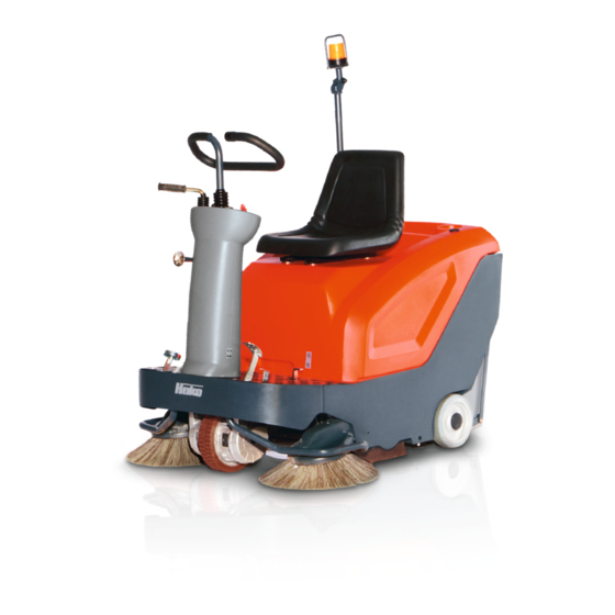
Operation Operation Overview 1 Operating panel 2 Steering column 3 Pedals 4 Side broom 5 Drive 6 Larger debris flap 7 Sealing strips, broom space 8 Cylindrical broom 9 Dirt hoppers 10 Panel air filter 11 Seat console 12 Driver's seat 13 Flashing light (option) Fig.3... -
Page 18: Function Description
Operation Function description Filter system The Sweepmaster is a sweeper exclu- The fine dust swirled up by the cylindri- sively designed for sweeping up dry cal broom is forced into the panel air fil- and wet waste from floor surfaces as in ter (Fig. -
Page 19: Special Equipment
Operation Seat console 2.2.1 Special equipment 2.2.2 Spare part requirements The basic vehicle can be upgraded by The seat console (Fig. 3/11) can be piv- adding various special equipment. The oted up for maintenance work. The seat Spare part Order no.: order numbers for these components console is provided with a safety sup- are listed in the table. -
Page 20: Operating Panel
Operation Operating panel 1 Key switch 2 Charge control indicator 3 Charge status indicator 4 Operating hour counter 5 Sweeping functions switch 6 Drive direction switch 7 Steering 8 Horn 9 Side broom lever Fig.4... - Page 21 Operation discharge status of the batteries by Key switch (Fig. 4/1) means of a red LED (Fig. 4/3B) and The key switch serves to switch the three green LEDs (Fig. 4/3C). When all electric drive on and off. three green LEDs light up, the batteries Remove the key to protect the are fully charged.
- Page 22 Operation celerate again. Operating hour counter (Fig. 4/4) It serves to display the operating hours. The counter only works when the driver Steering (Fig. 4/7) is seated in the seat and the ignition is The steering transmission from the switched on. steering wheel to the front wheel is per- formed by a fork head.
-
Page 23: Operating Elements On The Ve
Operation Operating elements on the vehicle 1 Driver's seat adjustment lever 2 Charger power cable 3 Shaking device lever 4 Accelerator 5 Folding apron pedal 6 Parking brake 7 Service brake Fig.5... - Page 24 Operation Driver's seat adjustment lever If the pedal is released, it automatically (Fig. 5/1) returns to its zero position and the vehi- The lever is used to adjust the seat po- cle comes to a stop. sition of the driver's seat. Pull the lever upwards and slide the Folding apron pedal (Fig.
- Page 25 Operation 1 Bypass flap 2 Adjusting bolt for right-hand side broom 3 Adjusting bolt for left-hand side broom (option) 4 Adjusting bolt for cylindrical broom 5 Safety support for seat console Fig.6...
- Page 26 Operation Bypass flap (Fig. 6/1) Safety support for seat console When sweeping wet surfaces or wet re- (Fig. 6/5) fuse, open the bypass flap. Close the Only operate the vehicle when bypass flap again to sweep dry surfac- the seat console is closed. Adjusting bolt for right-hand side Only open the seat console for mainte- nance and repair work.
- Page 27 Operation Dirt hopper lock (Fig. 7/1) The lock serves to secure the dirt hop- pers. To empty the dirt hoppers (Fig. 7/ 2), pivot the lock lever (Fig. 7/1) up and remove the dirt hoppers. Fig.7...
-
Page 28: Operation
Operation Operation Unpacking 1. Remove the packaging and tighten- ing straps. 2. Park the machine by applying the parking brake. 3. Remove the wooden chock. 4. Remove the rear skirting panel and assemble it under the front one. 5. Release the parking brake and push the machine from the pallet. -
Page 29: Before Starting Up For The First
Also observe the information in the op- Only technicians from your local autho- erating manual enclosed with the char- rized Hako dealer are allowed to pro- ger and the operating manual supplied vide initial instruction on the machine. by the battery manufacturer in this The manufacturing plant will notify the case. -
Page 30: Adjusting The Driver's Seat
Operation Adjusting the driver's seat The driver's seat (Fig. 9/1) must be ad- justed so that the driver is seated com- fortably and can reach all the operating elements with ease. Pull the lever (Fig. 9/2) upwards and slide the driver's seat to the required seat position. -
Page 31: Switching The Vehicle On
Operation Switching the vehicle on For safety reasons, the driver's seat is equipped with a seat contact switch. The machine can only be put into operation when an operator is sitting on the driver's seat. The function of the seat contact switch must not be bypassed. -
Page 32: Stopping And Switching Off The Vehicle
Operation Stopping and switching off the vehicle 1. Move the accelerator (Fig. 11/1) slowly to its zero setting. The vehicle slows down to a stop. If this braking effect is insuffi- cient, you can also apply the service brake (Fig. 11/2) to de- celerate more quickly. -
Page 33: Sweeping Operation
Operation Sweeping operation 1 Charge status indicator 2 Shaking device 3 Dirt hoppers 4 Bypass flap 5 Driver's seat 6 Key switch 7 Drive direction switch 8 Sweeping functions switch 9 Side broom lever 10 Accelerator Fig.12... - Page 34 Operation cleaned. Check prior to sweeping operation • Check the charge status indicator After switching on the sweep- (Fig. 12/1) of the batteries ing functions, drive off straight • Clean the filters using the shaking away to avoid the risk of the cy- device (Fig.
-
Page 35: Charging Batteries
Operation Charging batteries 1 Charge status indicator 2 Key switch 3 Power cable 4 Charge control indicator Fig.13... - Page 36 Operation During operation, the charge status in- dicator (Fig. 13/1) displays the dis- charge status of the batteries. When the red LED lights up, the battery must be charged immediately. 1. Switch the vehicle off using the key switch (Fig. 13/2) and secure with the parking brake.
-
Page 37: Operating The Shaking Device
Operation Operating the shaking device Pull and push the lever (Fig. 14/1) in and out quickly, several times in suc- cession in order to clean the dust from the panel air filter. Only operate the shaking de- vice when the electric drive is switched off. -
Page 38: Emptying The Dirt Hoppers
Operation Emptying the dirt hoppers Check the contents of the dirt hoppers regularly and empty as necessary. Pivot the lock lever (Fig. 15/1) upwards and remove the dirt hoppers (Fig. 15/2). Transport the dirt hoppers using the handles (Fig. 15/3). Risk of injury! For reasons of health, each dirt hopper should only be filled to... -
Page 39: Fault Location
Clean the panel air filter Dirt hoppers full Empty the dirt hoppers Drive belt defective Change the drive belt Drive motor defective Contact Hako service Machine swirls dust Sealing strips on broom space Adjust or change the sealing strips worn Panel air filter soiled... -
Page 40: Loading And Transporting
Operation 3.11 Loading and transporting When the vehicle is loaded and transported to the location of use, the side broom must be raised. Loading Take the weight of the machine into ac- count when loading, refer to Section "Technical Data". Transporting The vehicle must be properly secured. -
Page 41: Technical Data
Technical Data Technical Data Vehicle length (with side broom) Vehicle height (over steering wheel) Vehicle width (with right-hand side broom) Working width (with right-hand side broom) Cylindrical broom width Cylindrical broom diameter Cylindrical broom speed Side broom diameter Side broom speed Area coverage, theoretical (with right-hand side broom) m²/h 5340... - Page 42 Technical Data Noise emission values The sound pressure level (LpA) (at the ear of the operator) measured according to DIN IEC 60335-2-72 under normal working conditions is: dB (A) Measurement inaccuracy (KpA): dB (A) The sound power level (LwAd) measured according to DIN EN 60335-2-72 under dB (A) normal working conditions is: Vibration values...
-
Page 43: Maintenance And Service
Hako system maintenance I: Hako system maintenance: (Every 125 operating hours) vice • ensures the Hako working vehicle is Must be completed by a skilled techni- always ready for operation (preven- General information cian in an authorized Hako service cen-... -
Page 44: Maintenance Report
Maintenance and Service Maintenance report Handover Hako System Maintenance I Hako System Maintenance II Hako System Maintenance I 125 operating hours 250 operating hours 375 operating hours Upgrading Workshop Stamp Workshop Stamp Workshop Stamp Test drive Handover to customer Instruction... -
Page 45: Maintenance Plan
Maintenance and Service Maintenance plan Hako system maintenance, cus- tomer The following maintenance work must be completed by the customer at the in- tervals stipulated. Interval Activity Daily Weekly Check battery charge; charge battery, if necessary Clean broom space of cylindrical broom... - Page 46 Maintenance and Service Hako system maintenance I The following maintenance work must be completed by an authorized Hako service center. Interval Activity Every 125 operating hours Check battery and charger Check side broom for signs of wear and damage; change, if necessary Check cylindrical broom for signs of wear and damage;...
- Page 47 Interval Activity Every 250 operating hours All maintenance work in accordance with Hako system maintenance I Check fan belt; adjust belt tension or change fan belt, if necessary Check the visual appearance of the vehicle Test drive and function test of all safety-related components...
- Page 48 Interval Activity Every 500 operating hours All maintenance work in accordance with Hako system maintenance I and II Check electrical systems (operating panel, on-board charger, battery poles, cables, seat contact switch, lighting, fuses, relays and control lamps) Check the carbon brushes of the drive motor and central motor for ease of move- ment and signs of wear;...
-
Page 49: Battery System
Only batteries approved by Hako may be installed. Batteries may only be handled and changed by properly skilled maintenance person- nel. -
Page 50: Removing The Batteries
When free batteries approved by away! disconnecting, remove the Hako may be installed and at negative cable first. When con- the intended position. For more information on caring necting, connect the positive for driving batteries, also refer 1. -
Page 51: Setting The Battery Type
When battery sizes other than 100Ah to The two settings for GiV are equivalent. PzS** 117Ah, the on-board charger must be The DIP setting OFF-ON-ON-OFF is adjusted by Hako service technicians. the preferred setting. * X1-6...X1-7 - open ** X1-6...X1-7 - jumper... -
Page 52: Side Brooms
Maintenance and Service Side brooms When completing any mainte- nance and repair work, switch the machine off via the key switch to prevent the drive be- ing started up inadvertently! 1 Seat console 2 Safety support 3 Adjusting bolt, side broom, right 4 Side broom 5 Retaining screws, side broom Side broom, left (option) -
Page 53: Changing The Side Brooms
Maintenance and Service (Fig. 19/4) touches the ground. 5.5.1 Changing the side brooms Check the side broom (Fig. 19/4) every For the left-hand side broom week and change in the case of wear. (option), use the adjusting bolt 1. Switch the vehicle off using the key (Fig. -
Page 54: Cylindrical Broom
Maintenance and Service Cylindrical broom When completing any mainte- nance and repair work, switch the machine off via the key switch to prevent the drive be- ing started up inadvertently! 1 Seat console 2 Adjusting bolt for cylindrical broom 3 Dirt hoppers 4 Seals, dirt hoppers 5 Broom space 6 Sealing strips, broom space... -
Page 55: Cleaning The Broom Space
Maintenance and Service 5. Switch on the vehicle and allow the 5.6.1 Cleaning the broom space Check the broom space (Fig. 20/5) dai- cylindrical broom to rotate briefly ly for soiling and clean it as necessary. while at a standstill. 1. - Page 56 Maintenance and Service 5.6.3 Changing the cylindrical broom Check the cylindrical broom (Fig. 21/3) weekly and change it in the case of wear. 1. Switch the vehicle off using the key switch and secure with the parking brake. 2. Remove the dirt hoppers (Fig. 21/1). 3.
-
Page 57: Changing The Sealing Strips In
Maintenance and Service 5.6.4 Changing the sealing strips in the broom space The broom space is sealed by means of four sealing strips. Check the four seal- ing strips on a weekly basis and change them in the case of wear. 1. -
Page 58: Changing The Seals On The Dirt Hoppers
Maintenance and Service 5.6.5 Changing the seals on the dirt hoppers There are two seals fitted between the broom space and dirt hoppers. Check the two seals weekly and change in the case of wear. 1. Switch the vehicle off using the key switch and secure with the parking brake. -
Page 59: Vacuuming Dust
Maintenance and Service Vacuuming dust When completing any mainte- nance and repair work, switch the machine off via the key switch to prevent the drive be- ing started up inadvertently! 1 Panel air filter 2 Seal 3 Hood 4 Knurled nuts 5 Locking handle 6 Lever for shaking device 7 Safety support... -
Page 60: Shaking The Panel Air Filter
Maintenance and Service and seal (Fig. 24/2) and clean or 5.7.1 Shaking the panel air filter Clean the panel air filter (Fig. 24/1) in change them as necessary. the dust vacuum regularly and as nec- 5.7.3 Cleaning the panel air filter essary using the shaking device: Drop the panel air filter (Fig. -
Page 61: Drive Belt
Maintenance and Service Drive belt The drive belt for side broom, cylindrical broom and suction turbine must be checked every 250 operating hours and changed in the case of wear. 5.8.1 Changing the drive belt 1. Switch the vehicle off using the key switch and secure with the parking brake. -
Page 62: Electrical Installation
Maintenance and Service Electrical installation 5.9.1 Fuses F1 Hydraulic motor (70A) F2 Drive motor (50A) F3 Key switch (10A) 5.9.2 Relays K1 Working mode K2 Drive motor K3A Enable drive mode K3B Enable operating mode K3A/B Fig.26... -
Page 63: Ec Declaration Of Conformity
EC Directives: Ludger Lüttel bears sole responsibility for declaring that the products EN 60335-2-72 EN 55012 Sweepmaster B800 R EN 61000-6-2 Typ: 6400.20 to which this declaration relates, con- Bad Oldesloe, 22.04.2014 form to the relevant provisions of the... - Page 64 Spitzentechnik für eine saubere und schönere Umwelt Advanced Technology for a Cleaner, Better Environment · · Hako GmbH Hamburger Str. 209-239 D-23843 Bad Oldesloe · +49 4531 806-0 Fax +49 4531 806-338 ...
Need help?
Do you have a question about the Sweepmaster B800 R and is the answer not in the manual?
Questions and answers