Evolution RAGE5-S Original Instructions Manual
Hide thumbs
Also See for RAGE5-S:
- Original instructions manual (88 pages) ,
- Original instructions manual (120 pages) ,
- User manual

Related Manuals for Evolution RAGE5-S


Summary of Contents for Evolution RAGE5-S
- Page 1 RAGE5-S Original Instructions Instructions Originales Written originally in UK English Date Published: 01/07/2016...
-
Page 2: Table Of Contents
www.evolutionpowertools.com tABLE oF contEntS IntRoductIon Page 3 oPERAtIon Page 19 Guarantee Page 3 On/Off Safety Switch Page 19 Machine Specification Page 4 Raising/Lowering the Blade Page 19 Labels and Symbols Page 5 Tilting the Blade Page 19 Intended use of this Power Tool Page 6 The Rip Fence Page 20... -
Page 3: Introduction
We sincerely thank you for selecting a product chisels or paddles, etc. In no event shall from Evolution Power Tools. Evolution Power Tools be liable for loss or damage resulting directly or indirectly from EVoLutIon’s LIMItEd GuARAntEE the use of our merchandise or from any other Evolution Power Tools reserves the right cause. -
Page 4: Machine Specification
www.evolutionpowertools.com MAchInE SPEcIFIcAtIonS MACHINE MEtrIC IMpErIAl Motor UK/EU: 220-240V ~ 50Hz (S6 40%) 1800W 8.5A Motor UK: 110V ~ 50Hz 1600W 15.8A Minimum Table Surface Area: 745mm x 640mm 29-1/4 x 25-1/4 In. Maximum Table Surface Area: 1200mm x 640mm 47-1/4 x 25-1/4 In. -
Page 5: Labels And Symbols
WARnInG: Do not operate this machine if • The measurement and assessment of warning and/or instruction labels are missing human exposure to hand-transmitted or damaged. Contact Evolution Power Tools vibration in the workplace is given in: for replacement labels. BS EN ISO 5349-1:2001 and... -
Page 6: Intended Use Of This Power Tool
PoWER tooL Volts WARnInG: This product is a table saw and Amperes has been designed to be used with special Evolution blades. Only use accessories Hertz designed for use in this machine and/or Speed those recommended specifically by Evolution Power tools Ltd. -
Page 7: Safety Precautions
www.evolutionpowertools.com SAFEtY PREcAutIonS (2.2) 1) General Power tool Safety Warnings [Work area safety] (1.14) ELEctRIcAL SAFEtY a) Keep work area clean and well lit. Cluttered This machine is fitted with the correct moulded or dark areas invite accidents. plug and mains lead for the designated market. b) Do not operate power tools in explosive If the mains lead or the plug are damaged in atmospheres, such as in the presence... - Page 8 www.evolutionpowertools.com (2.4) (2.5) 3) General Power tool Safety Warnings 4) General Power tool Safety Warnings [Personal Safety]. [Power tool use and care]. a) Do not force the power tool. Use the correct a) Stay alert, watch what you are doing and power tool for your application.
-
Page 9: Additional Safety Instructions
www.evolutionpowertools.com do not use saw blades which are • (2.7) hEALth AdVIcE damaged or deformed. WARnInG: When using this machine, dust Replace the table insert/access • plate if worn. particles may be produced. In some instances, use only blades as recommended in depending on the materials you are working •... - Page 10 • disconnect from the power supply worn. Use only a genuine Evolution riving before servicing, cleaning and/or when knife as this is a dedicated component for this machine.
-
Page 11: Getting Started
For instructions on how to identify the batch equal to or greater than 100 A per phase. code, please contact the Evolution Power Tools helpline or go to: (4.1) www.evolutionpowertools.com... -
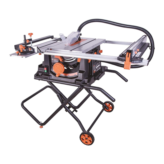
Page 12: Machine Overview
www.evolutionpowertools.com MAchInE oVERVIEW A. on/oFF SWItch SERIAL nuMBER / RAtInG LABEL B. hoLd doWn cLAMP K. RISE And FALL / BEVEL AdJuStMEnt hAnd WhEEL c. SLIdInG MItRE FEncE / MAtERIAL PuShER BEVEL LocKInG LEVER d. BLAdE (not VISIBLE) M. LAtchInG PIn RIVInG KnIFE (not VISIBLE) n. -
Page 13: What's In The Box
www.evolutionpowertools.com WhAt’S In thE BoX LAtchInG PIn LocKInG LAtch 1. StAnd coMPonEnt A. M8 X 78MM BoLt B. M6 X 53MM BoLt 2. StAnd coMPonEnt 3. StAnd coMPonEnt c. M5 X 50MM BoLt 4. StAnd coMPonEnt d. M5 X 40MM BoLt 5. -
Page 14: Assembly
www.evolutionpowertools.com ASSEMBLY to assemble this saw you will need: Cross head screwdriver, 8mm & 10mm spanner or socket wrench, 13mm Socket wrench, 5mm allen key and a rubber mallet. note: This process can be considerably aided by studying the images of the assembled machine and the components found on the machine overview &... - Page 15 www.evolutionpowertools.com Fig. 1 Fig. 2 Fig. 3 Fig. 4 Fig. 5 Fig. 6 Fig. 8 Fig. 9 Fig. 7 Fig. 10 Fig. 11 Fig. 12...
-
Page 16: Riving Knife
www.evolutionpowertools.com Some further minor assembly is required to commission this machine. WARnInG: This machine is heavy. Enlist competent help when removing this machine from its packaging. dEPLoYInG thE LEGS The legs are stored underneath the machines main body. • Release the retaining latch (Fig 13). • Deploy the legs. -
Page 17: Blade Guard
www.evolutionpowertools.com thE BLAdE GuARd The Blade Guard labelled 9 must be attached to the machines riving knife. note: The machine should never be used without this guard in its service position. WARnInG: The machine must be disconnected from the mains supply when installing the blade guard. To attach the Blade Guard Fig. -
Page 18: Checking/Adjusting The Rip Fence
www.evolutionpowertools.com chEcKInG/AdJuStInG thE RIP FEncE When the Rip Fence has been attached to the machine, the Rip Fence should be checked to ensure that it lies parallel to the blade. • Raise the blade to its full height. • Rest a straight-edge or similar against the blade. • Bring the Rip Fence up to the straight-edge and check for parallelism. • If adjustment is needed, gain access to the two hex headed screws located on the Rip Fence (Fig. -
Page 19: Operation
www.evolutionpowertools.com oPERAtIonS thE contRoLS on/oFF SAFEtY SWItch WARnInG: Before operating the ON/OFF switch make sure that the blade guard is correctly installed and operating properly. The machine is equipped with a NVR (no volt release) switch. To start the machine lift the cover plate to reveal the on and off Fig. -
Page 20: The Rip Fence
www.evolutionpowertools.com thE RIP FEncE This machine is fitted with a two piece Rip Fence. We recommend that the Rip Fence is normally used in conjunction with its adjustable Face Plate. The Rip Fence should normally be positioned to the RH side of the blade. -
Page 21: Multifunction Table Top
www.evolutionpowertools.com note: The face plate of the mitre gauge should be adjusted so that it passes close to, but does not touch the blade guard as it slides past during a cut. Adjust by loosening the finger nuts and sliding the faceplate to the required position. -
Page 22: Sliding Carriage
www.evolutionpowertools.com SLIdInG cARRIAGE This machine is fitted with a Sliding Carriage (Fig. 36) to the LH side of the blade. This facility can be particularly useful when cross-cutting small section material such as metal box- section or extrusions etc. Such material can be clamped to the Sliding Carriage by using the secured Mitre Gauge and its Hold Down Clamp. -
Page 23: Crosscutting
www.evolutionpowertools.com cRoSScuttInG Set the Mitre Gauge to 0˚ and tighten the vertical locking screw. If employing the Sliding Carriage position the Mitre Gauge in the LH ‘T’ slot and lock it in place by screwing the locking screw into the locating hole. note: The Mitre Gauge can be used on the RH side of the blade if required. -
Page 24: Repetitive Cross-Cutting
www.evolutionpowertools.com REPEtItIVE cRoSS cuttInG Repetitive Cross Cutting is the process of cutting a number of pieces to the same length without having to mark out each piece separately. note: We recommend that repetitive cross-cutting is carried out with the Mitre Gauge positioned on the LH side of the machine, with the Rip Fence on the RH side of the machine (Fig. -
Page 25: Bevel Ripping
If the push stick becomes damaged it should be replaced. If the operator makes their own push stick, we recommend that it follows the same pattern as that supplied. (Replacement push sticks are available from Evolution Power Tools.) MAIntEnAncE WARnInG: Ensure that the machine is disconnected from the mains supply before any maintenance tasks or adjustments are attempted. -
Page 26: Riving Knife
Inspect the riving knife at regular intervals and replace it if it is worn or damaged. note: Use only a genuine Evolution Riving Knife, as this is a dedicated component for this machine. Non genuine parts could Fig. 51 be dangerous. -
Page 27: Declaration Of
In accordance with EN ISO 17050-1:2004 the manufacturer of the product covered by this declaration is: Evolution Power Tools, Venture One, Longacre Close, Holbrook Industrial Estate, Sheffield, S20 3FR. The manufacturer hereby declares that the machine as detailed in this declaration fulfils all the relevant provisions of the Machinery Directive and other appropriate directives as detailed below. - Page 28 Evolution Power Tools Ltd Evolution Power Tools LLC Evolution Power Tools SAS Venture One 8363 Research Drive 61 Avenue Lafontaine Longacre Close Davenport 33560 Holbrook Industrial Estate Iowa Carbon-Blanc Sheffield 52806 Bordeaux S20 3FR +44 (0)114 251 1022 +1 866-EVO-TOOL...
Need help?
Do you have a question about the RAGE5-S and is the answer not in the manual?
Questions and answers