Table of Contents
Advertisement
Installation, Operation
and Maintenance
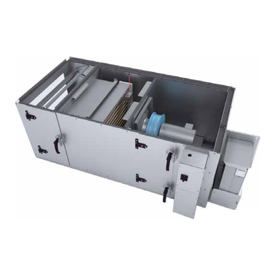
Performance Climate Changer Air Handler
Model UCCA
Sizes 3-30
Only qualified personnel should install and service the equipment. The installation, starting up, and servicing of heating, ventilating, and air-
conditioning equipment can be hazardous and requires specific knowledge and training. Improperly installed, adjusted or altered equipment
by an unqualified person could result in death or serious injury. When working on the equipment, observe all precautions in the literature and
on the tags, stickers, and labels that are attached to the equipment.
January 2014
SAFETY WARNING
CLCH-SVX009A-EN
*X39641253010*
X-39641253010
Advertisement
Table of Contents

Related Manuals for Trane UCCA


Summary of Contents for Trane UCCA
- Page 1 Installation, Operation and Maintenance Performance Climate Changer Air Handler Model UCCA Sizes 3-30 *X39641253010* SAFETY WARNING Only qualified personnel should install and service the equipment. The installation, starting up, and servicing of heating, ventilating, and air- conditioning equipment can be hazardous and requires specific knowledge and training. Improperly installed, adjusted or altered equipment by an unqualified person could result in death or serious injury.
-
Page 2: Warnings, Cautions And Notices
Hydrogen, Chlorine, Fluorine and or serious injury. Carbon (HCFCs). Not all refrigerants containing these compounds have the same potential impact to the environment. Trane advocates the responsible handling of all refrigerants-including industry replacements for CFCs such as HCFCs and HFCs. Responsible Refrigerant Practices! - Page 3 Warnings, Cautions and Notices Performance air handler model UCCA is not designed for use with UV lights. WARNING Harmful Ultraviolet (UV) Lights! Failure to follow instructions below could result in death or serious injury and equipment damage. Do not field install ultraviolet lights in this air handling unit for the intended purpose of improving indoor air quality.
-
Page 4: Table Of Contents
Table of Contents Warnings, Cautions and Notices Filter Placement .....26 ..2 Duct Connections . - Page 5 External Insulating Requirements ..53 Routine Maintenance ....54 Maintenance Checklist ....54 Air Filters .
-
Page 6: Introduction
Use this manual to install, startup, operate, and maintain unit model number. the Performance Climate Changer™ air handler model UCCA. Carefully review the procedures discussed in this Note: The unit serial number and order number is manual to minimize installation and startup difficulties. -
Page 7: General Information
Operating Environment Unit Description Performance Climate Changer™ air handler model UCCA The Performance air handler model UCCA is designed for is designed for indoor applications. When considering the budget-conscience applications, but does not sacrifice on placement of the air handler, it is important to consider the construction, quality, or performance. -
Page 8: Factory-Mounted Controls
WARNING stand-alone operation, or it can be fully integrated into a Proper Field Wiring and Grounding comprehensive control system. The Trane Earthwise™ Required! system incorporates the benefits of factory-installed controls and links the air handler to the Tracer™ SC system All field wiring MUST be performed by qualified controls building management system. -
Page 9: Model Number Description
Digit 13 - Coil #1 first in Digit 17 - Electric heat/factory airstream mounted UCCA = Performance Climate Changer Air Handler 0 = No unit coil #1 0 = No electric heat A = 1 row preheat hydronic/9 fins per in. - Page 10 Model Number Description Digit 22 - Refrigerant circuit Digit 25 - Drives 69 = 69 hertz/2049 rpm 70 = 70 hertz/2079 rpm options 0 = None 71 = 71 hertz/2109 rpm A = 650 rpm fixed/600-700 rpm variable 0 = None 72 = 72 hertz/2138 rpm B = 700 rpm fixed/650-750 rpm variable 1 = Single refrigerant circuit arr with...
- Page 11 Model Number Description Digit 29 - Filter type 0 = Customer supplied/no filters A = 2-in. MERV 8 B = 2-in. MERV 13 C = 2-in. MERV 8/4-in. MERV 11 D = 2-in. MERV 8/4-in. MERV 13 E = 2-in. MERV 13/4-in. MERV 13 S = Special Digit 30 - Controls options 1 0 = None...
-
Page 12: Pre-Installation
Upon delivery, thoroughly inspect all components for any Notify your Trane sales representative of the damage shipping damage that may have occurred, and confirm and arrange for repair. Do not attempt to repair the unit that the shipment is complete. -
Page 13: Long-Term Storage
Pre-Installation Long-Term Storage NOTICE: For longer periods of storage, allow proper clearance around the unit to perform periodic inspections and Microbial Growth! maintenance on the equipment. While the unit is in The floor or foundation must be level and the storage: condensate drain at the proper height for proper coil •... -
Page 14: Dimensions And Weights
Dimensions and Weights Service Clearances Figure 2. Service clearances Mixing Box/Filter Control box Electric and fan heat Coil Filter Table 1. Service clearance dimensions (inches) Unit Size Letter Component Filter 40.00 44.00 42.00 42.00 40.00 45.00 45.00 45.00 51.00 51.00 Coil 49.00 62.00... - Page 15 Dimensions and Weights Table 2. Performance air handler model UCCA data 1500 3000 4000 5000 6000 7000 3500 10,500 12,500 15,000 Nom airflow (CFM) Unit size Horz unit height (in.) 27.50 32.50 38.00 38.00 41.80 45.60 48.10 54.30 60.60 60.60 Horz unit width (in.)
- Page 16 Dimensions and Weights Table 2. Performance air handler model UCCA data 1500 3000 4000 5000 6000 7000 3500 10500 12500 15000 Nom airflow (CFM) Unit size Fan/Motor data FC fans Wheel size (in.) 12x9 12x12 15x15 18x15 18x18 20x15 20x20...
-
Page 17: Fans
Dimensions and Weights Fans Table 3. Fan weights (pounds) - no motor Unit Size FC Fan DDP Fan 30.71 60.63 47.09 96.03 69.21 110.09 83.02 149.12 97.90 158.25 110.46 164.44 133.09 172.89 155.81 290.14 168.83 304.07 208.34 317.00 Note: Add motor weight to get total weight of fan. Motors Table 4. - Page 18 Dimensions and Weights Table 5. VFD Weights (pounds) and Line Input VFD (single Fan) VFD (dual Fan) Type Line Input Weight Line Input Weight 208 V / 60 Hz / 3 PH 3.50 1800 4.20 230 V / 60 Hz / 3 PH 3.00 1800 4.20...
-
Page 19: Installation - Mechanical
Installation - Mechanical Lifting and Rigging Vertical FC Fan 3-10 1. Remove screws attaching shipping protection brackets Remove Shipping Tie-Downs from center of isolation base to casing mounting bracket. Prior to unit placement, remove the shipping tie-downs. 2. Remove shipping protection brackets through door. Figure 3 thru Figure... -
Page 20: General Lifting Considerations
Installation - Mechanical FC Fan Size 12-30 General Lifting Considerations 1. Remove drive side screws on isolator brackets 2. Cut banding and remove WARNING Risk of Unit Dropping! Figure 7. Shipping tie-down removal for FC fan 12-30 Do not use skid tie down brackets to lift the unit. Improper use of the tie down brackets could result in unit dropping and crushing technicians which could result in death or serious injury, and equipment... -
Page 21: Skid Removal
Installation - Mechanical Figure 11. Hoist unit with slings and spreader bars WARNING Improper Unit Lift! Spreader bar Test lift unit approximately 24 inches to verify proper center of gravity lift point. To avoid dropping of unit, reposition lifting point if unit is not level. Failure to properly lift unit could result in unit dropping and possibly crushing operator/technician which could result in death or serious injury and possible equipment... -
Page 22: Unit Placement And Assembly
Installation - Mechanical Unit Placement and Assembly Floor Mounting The skid tie down brackets can be used to tie down the unit • If the air handler is ordered with a mixing box or angle to the concrete slabs or other flat surface. Do not use tie filter section, it will arrive in sections. -
Page 23: Unit Assembly
Installation - Mechanical Figure 14. Typical ceiling suspension for parallel-to-airflow channels and perpendicular-to-airflow channels Unit Assembly Figure 15. Bring sections close, remove strap channels. Note: Air handlers often include optional factory- provided casing penetration entry points for field- provided wiring. Consider overall unit serviceability and accessibility before mounting, running wires (power), making cabinet penetrations, or mounting any components to the... -
Page 24: Fan Removal
Installation - Mechanical 3. Slide the sections together so the side flanges overlap Figure 17. Remove screws, install lifting lugs the main section. 4. Align the top and bottom holes and replace the screws. Figure 16. Bring sections together, align holes. (1) Lifting lug # LUG00180 Temporarily use for lifting second level. - Page 25 Installation - Mechanical Figure 19. Check gasket between sections, replace if Figure 18. Use spreader bars to lift top unit necessary (4) Gasket: 0.188T x 1.50W # GKT03823 Align to the edge of the panel. Joint gasket should overlap 1/2 inch 2.25 4.25 Airflow...
-
Page 26: Filter Placement
Installation - Mechanical Filter Placement Figure 20. Flat filter arrangement Size 8 Size 10 Size 6 8.90 ft² Size 3 11.10 ft² 6.90 ft² 3.50 ft² 7.00 9.00 3.00 2.00 2.00 5.00 3.50 3.50 34.00 34.00 28.50 23.50 30.00 43.00 47.00 59.00 Size 14... -
Page 27: Duct Connections
Installation - Mechanical Figure 21. Angle filter arrangement Size 3 Size 6 Size 8 Size 10 12.50 ft² 15.60 ft² 5.60 ft² 11.10 ft² 3.00 2.00 3.00 5.00 30.00 43.00 47.00 59.00 Size 17 30.00 ft² Size 12 Size 14 3.00 21.70 ft²... -
Page 28: Fan Discharge Connections
Fan Discharge Conversion purchase a new v-belt. 12. Cut a hole in the discharge panel for the air discharge Performance UCCA air handlers are available in the and cover the exposed foam insulation at the inside following arrangements: edges of the hole using the insulation cover channels •... -
Page 29: Adjusting The Isolators
Installation - Mechanical Table 6. Minimum isolator clearance Figure 23. Contact Service Parts for top/front duct extension kit Unit size Required Clearance 3-10 1 inch 12-30 3/8 inch Figure 25. Isolator adjustment for sizes 3-8 Top/Front Required Clearance 14. The duct extensions do not extend as far and do not reach the cabinet panel. -
Page 30: Coil Piping And Connections
Condensate drain connections are provided on only one side of the coil section. Pitch the connection lines horizontal or downward toward an open drain. Trane Proper installation, piping, and trapping is necessary to recommends installing a plug to facilitate cleaning of the ensure satisfactory coil operation and to prevent trap. -
Page 31: Steam Coil Piping
Coil Piping and Connections Figure 28. Drain pan trapping for negative and positive pressure applications Drain pan trapping for section Drain pan trapping for section under negative pressure under positive pressure L = H + J + pipe diameter where: L = H + J + pipe diameter where: H = 1 inch for each inch of negative H = 1/2 inch (minimum) - Page 32 25 psig or higher. damage. Note: Trane steam coils require a minimum of 2 psi of pressure to assure even heat distribution. To prevent coil damage, complete the following recommendations: 2.
-
Page 33: Water Coil Piping
Coil Piping and Connections Water Coil Piping is below these minimums, vent the coil by one of the following methods: Figure 30 Figure 31 illustrate typical water coil piping 1. Install an air vent in the top pipe plug tapping of the configurations. -
Page 34: Refrigerant Coil Piping
Coil Piping and Connections Refrigerant Coil Piping Figure 32 illustrates an example of a split-system component arrangement. Use it to determine the proper, relative sequence of the components in the refrigerant Note: Refer to for information on handling refrigerants. lines that connect the condensing unit to an evaporator coil. -
Page 35: Liquid Lines
(MCHE), solenoid valves isolate the refrigerant from the evaporator during the off cycles. Trim solenoids cannot be used with MCHE. Coil Note: Trane condensing units with MCHE no longer employ pump-down, but isolation solenoids are • Ball shutoff valves. Adding manual, ball-type shutoff required. -
Page 36: Suction Lines
Components Trane now has many years of experience in the successful Installing the suction line requires field installation of use of equipment without hot gas bypass in commercial these components: a filter, access port, and a Frostat™... -
Page 37: Remodel, Retrofit, Or Replacement
For have a negligible effect on performance and reliability. specific handling concerns with R-410A, please contact your local Trane representative. NOTICE: Every part of an existing split system needs to be analyzed Compressor Damage! to determine if it can be reused in an R-410A and POE oil POE oil is hygroscopic –... -
Page 38: Field-Installed Evaporator Piping Examples
Coil Piping and Connections Field-Installed Evaporator Piping Examples Figure 34. Single-circuit condensing unit: evaporator coil with one distributor Evaporator Coil with Standard Circuiting suction line liquid line sight glass thermal solenoid filter drier expansion valve valve (TXV) distributor 1. Pitch the liquid line slightly—1 inch/10 feet —so that the refrigerant drains toward the evaporator. - Page 39 Coil Piping and Connections Figure 35. Single-circuit condensing unit: evaporator coil with two distributors 1. Pitch the liquid line slightly—1 inch/10 feet —so suction line Evaporator Coil the refrigerant drains toward the evaporator. with Horizontal-Split “trim” (Standard) Circuiting solenoid valve 2.
- Page 40 Coil Piping and Connections Figure 36. Single-Circuit Condensing Unit: Evaporator Coil with Four Distributors 1. Pitch the liquid line slightly—1 inch/10 feet —so Evaporator Coil that the refrigerant drains toward the with Horizontal-Split suction line thermal expansion (Standard) Circuiting evaporator. valves (TXV) 2.
- Page 41 Coil Piping and Connections Figure 37. Dual-circuit condensing unit: evaporator coil with two distributors Evaporator Coil suction line with Horizontal-Split (circuit 2) (Standard) Circuiting liquid line (circuit 2) sight glass solenoid distributor valve suction line (circuit 1) liquid line (circuit 1) thermal filter drier expansion...
- Page 42 Coil Piping and Connections Figure 38. Dual-circuit condensing unit: evaporator coil with four distributors 1. Pitch the liquid line slightly—1 inch/10 feet —so Evaporator Coil that the refrigerant drains toward the with Horizontal-Split (Standard) Circuiting evaporator. suction line (circuit 2) 2.
-
Page 43: Electrical Requirements
For variable frequency drives creating ground loops with grounded conductors external or other energy storing components provided by Trane to the unit control circuit. Ground loops can affect the or others, refer to the appropriate manufacturer’s measurement accuracy of the controller. -
Page 44: Fuse Sizes
Electrical Requirements Useful formulas: Figure 39. Interface power requirements kW = (Airflow x Delta T)/K Delta T = (kW x K)/Airflow Line K = 3145 (English) 24 Vac voltage Termination board K = 824.7 (SI) Heater input current = (kW x 1000)/(Voltage x 1.73) Transformer MCA = Minimum Circuit Ampacity MOP = Maximum Overcurrent Protection rating or... -
Page 45: Vfd Wiring Schematic
JJN-100 LINE ENCLOSURES INDICATE ALTERNATE CIRCUITRY LP-CC-10 OR AVAILABLE SALES OPTIONS. SOLID LINES 1.5, 2 LP-CC-10 INDICATE WIRING BY TRANE. LP-CC-15 LP-CC-15 3. NUMBERS ALONG THE RIGHT SIDE OF THE SCHEMATIC LP-CC-25 DESIGNATE THE LOCATION OF CONTACTS BY LINE LP-CC-25 NUMBER. - Page 46 COMPONENETS PROVIDED BY THE FIELD. PHANTOM SPLICE LINE ENCLOSURES INDICATE ALTERNATE CIRCUITRY OR AVAILABLE SALES OPTIONS. SOLID LINES SPLICE INDICATE WIRING BY TRANE. 1B2 - 28 3. NUMBERS ALONG THE RIGHT SIDE OF THE SCHEMATIC SPLICE DESIGNATE THE LOCATION OF CONTACTS BY LINE NUMBER.
- Page 47 Electrical Requirements Figure 42. Typical starter wiring schematic DEVICE DESCRIPTION ZONE MOTOR OVERLOAD RELAY FAN MOTOR CONTACTOR UNIT DISCONNECT SWITCH CONTROL TRANSFORMER MOTOR 1 SPLICE NOTES: 1. UNLESS OTHERWISE NOTED ALL SWITCHES ARE SPLICE SPLICE 208V ENERGIZED. 196001410002-60 196001410002-61 DEVICE PREFIX LOCATION CODE AREA LOCATION MAIN CONTROL PANEL...
-
Page 48: Start-Up
(see Table 16 on inadvertently energized. For variable frequency drives or other energy storing components provided by Trane page or others, refer to the appropriate manufacturer’s – Fan sheaves should be tight and aligned. -
Page 49: Motor-Related Checks
Units shipped with an optional variable frequency drive death or serious injury. (VFD) are preset and run-tested at the Trane factory. If a problem with a VFD occurs, ensure that the programmed parameters listed in Table 14 have been set. - Page 50 For variable frequency drives 40 - 125 or other energy storing components provided by Trane 0.5 - 10 or others, refer to the appropriate manufacturer’s literature for allowable waiting periods for discharge of 15 - 125 capacitors.
-
Page 51: Tension The Fan Belt
Start-Up Tension the Fan Belt Figure 44. Belt tensioner NOTICE: Belt Tension! (2 of 2) Do not over-tension belts. Excessive belt tension will reduce fan and motor bearing life, accelerate belt wear Force Scale Small O-Ring and possibly cause shaft failure. Under tensioning belts is the primary cause of premature belt failure. -
Page 52: Determine Fan Speed
Start-Up Table 15. Typical sheave diameter and deflection force Belt Deflection Force (lbs) Super gripbelts and Gripnotch belts and Smallest sheave unnotched gripbands notched gripbands Cross diameter range Speed (rpm) section (in.) range Used belt New belt Used belt New belt 1,000–2,500 3.0–3.6 2,501–4,000... -
Page 53: Align Fan And Motor Sheaves
Start-Up Align Fan and Motor Sheaves Figure 46. Proper drive alignment Align the fan and motor sheaves using a straightedge. The straightedge must be long enough to span the distance Center line between the outside edges of the sheaves. When the Lines must must coincide sheaves are aligned, the straightedge will touch both... -
Page 54: Routine Maintenance
Routine Maintenance WARNING WARNING Hazardous Service Procedures! Rotating Components! The maintenance and troubleshooting procedures The following procedure involves working with recommended in this manual could result in exposure rotating components. Disconnect all electric power, to electrical, mechanical or other potential safety including remote disconnects before servicing. -
Page 55: Air Filters
For to prevent air bypass. If using filters not supplied by personal safety refer to the cleaning agent Trane, apply foam gasketing to the vertical edges of manufacturer’s Materials Safety Data Sheet and follow the filter. -
Page 56: Refrigerant Coils
Routine Maintenance Figure 48. Gain access to both sides of coil shown for sizes 8, 14, 17, 21, 25, and 30 3. Wearing the appropriate personal protective 12. Allow the unit to dry thoroughly before putting it back equipment, use a soft brush to remove loose debris into service. -
Page 57: Coil Winterization
Water coil winterization procedures consist primarily of Hazardous Chemicals! draining water from the coil before the heating season. Trane recommends flushing the coil with glycol if coils will Coil cleaning agents can be either acidic or highly be exposed to temperatures below 35 degrees. -
Page 58: Drain Pans
Routine Maintenance Drive Motor and Pulley Replacement • Operates the supply fan for 10 to 15 minutes. Air movement discourages water condensation and hastens re-evaporation of any condensate that does WARNING happen to form. This simple preventative measure Hazardous Voltage! effectively combats microbial growth and curbs moisture- related deterioration of air-handling components. - Page 59 Routine Maintenance Figure 49. Resetting low limit switch for horizontal units Figure 50. Resetting low limit switch for vertical units with housed fans Low limit freeze stat Note: Fan access door removed for clarity only Low limit freeze stat Note: Fan access door removed for clarity Figure 51.
-
Page 60: Fans
Routine Maintenance Figure 52. Resetting low limit switch for horizontal DDP fan units sizes 8 and 14-30 Screw: 10-16 x 0.750 self-driller Remove all from perimeter of panel Low limit freeze stat Removable access panel Fans 4. Thoroughly clean any contaminated area(s) with a mild bleach and water solution or an EPA-approved sanitizer specifically designed for HVAC use. -
Page 61: Torque Requirements
Routine Maintenance Torque Requirements Table 19. Compatible Greases Refer to Table 18 for minimum torque of motor mounting Type and bearings bolts. Refer to Table 16, page 53 Texaco Multi Fak 2 minimum set screw torque. Shell Alvania 2 Mobil 532 Table 18. -
Page 62: Troubleshooting
Troubleshooting This section is intended to be used as a diagnostic aid only. For detailed repair procedures, contact your local Trane service representative. WARNING Hazardous Service Procedures! The maintenance and troubleshooting procedures recommended in this manual could result in exposure to electrical, mechanical or other potential safety hazards. - Page 63 Troubleshooting Table 21. Air handler troubleshooting recommendations Symptom Probable Cause Recommended Action Loosen bearing set screws and realign (see “Align Fan and Motor Poor alignment Sheaves,” page Bearing noise Failed bearing Replace bearing. Inadequate lubrication Replace bearing. Incorrect airflow Check fan operating condition. Inspect the water pumps and valves for proper operation and check the Incorrect water flow lines for obstructions.
- Page 64 HVAC systems, comprehensive building services, and parts. For more information, visit www.Trane.com. Trane has a policy of continuous product and product data improvement and reserves the right to change design and specifications without notice. © 2014 Trane All rights reserved...
Need help?
Do you have a question about the UCCA and is the answer not in the manual?
Questions and answers