Honeywell UDC3500 Product Manual
Universal digital controller
Hide thumbs
Also See for UDC3500:
- Product manual (422 pages) ,
- Application note (16 pages) ,
- Instruction (8 pages)
Table of Contents
Advertisement
Quick Links
Download this manual
See also:
Instructions
Advertisement
Table of Contents
Troubleshooting

Related Manuals for Honeywell UDC3500


Summary of Contents for Honeywell UDC3500
- Page 1 UDC3500 Universal Digital Controller Product Manual 51-52-25-120 March 2007 Honeywell Process Solutions Industrial Measurement and Control...
- Page 2 Contact your local sales office for warranty information. If warranted goods are returned to Honeywell during the period of coverage, Honeywell will repair or replace without charge those items it finds defective. The foregoing is Buyer's sole remedy and is in lieu of all other warranties, expressed or implied, including those of merchantability and fitness for a particular purpose.
- Page 3 This document provides descriptions and procedures for the Installation, Configuration, Operation, and Troubleshooting of your UDC3500 Controller. Contacts World Wide Web The following lists Honeywell’s World Wide Web sites that will be of interest to our customers. Honeywell Organization WWW Address (URL) Corporate http://www.honeywell.com...
- Page 4 Chassis Ground. Identifies a connection to the chassis or frame of the equipment shall be bonded to Protective Earth at the source of supply in accordance with national and local electrical code requirements. 3/07 UDC3500 Universal Digital Controller Product Manual...
-
Page 5: Table Of Contents
3.14 Output Set Up Group.......................106 3.15 Input 1 Set Up Group ......................117 3.16 Input 2 Set Up Group ......................121 3.17 Input 3 Set Up Group ......................124 3.18 Input 4 Set Up Group ......................127 UDC3500 Universal Digital Controller Product Manual 3/07... - Page 6 4.10.6 ACCUTUNE Error Codes ....................212 4.11 Fuzzy Overshoot Suppression ....................213 4.12 Using Two Sets of Tuning Constants..................214 4.13 Input Math Algorithms......................216 4.14 Logic Gate Operation ......................218 4.15 Digital Input Option (Remote Switching) ................221 3/07 UDC3500 Universal Digital Controller Product Manual...
- Page 7 Restore Input Factory Calibration....................293 OUTPUT CALIBRATION................... 295 Overview.............................295 First Current Output Calibration ....................296 Second Current Output Calibration.....................298 Third Current Output Calibration ....................300 Position Proportional and Three Position Step Output Calibration ..........302 Restore Factory Output Calibration ....................305 UDC3500 Universal Digital Controller Product Manual 3/07...
- Page 8 CODES........................347 10.1 Overview ..........................347 10.2 Reading Control Data......................350 10.3 Read Software Options Status ....................351 10.4 Miscellaneous Read Onlys ......................352 10.4.1 Register Addresses for Read Onlys ................352 10.4.2 SetPoint Program Read Only Information..............352 3/07 UDC3500 Universal Digital Controller Product Manual viii...
- Page 9 FURTHER INFORMATION................436 11.1 Modbus RTU Serial Communications ..................436 11.2 Modbus Messaging on Ethernet TCP/IP .................436 11.3 How to Apply Digital Instrumentation in Severe Electrical Noise Environments....436 INDEX ........................437 SALES AND SERVICE..................442 UDC3500 Universal Digital Controller Product Manual 3/07...
- Page 10 Table 4-5 Control Mode Definitions ___________________________________________________ 201 Table 4-6 Changing Control Modes ____________________________________________________ 202 Table 4-7 Procedure for Changing the Local Setpoints _____________________________________ 203 Table 4-8 Procedure for Switching Between Setpoints _____________________________________ 203 3/07 UDC3500 Universal Digital Controller Product Manual...
- Page 11 Table 6-5 Set Up Wiring Procedure for the Third Current Output ____________________________ 300 Table 6-6 Third Current Output Calibration Procedure _____________________________________ 301 Table 6-7 Position Proportional and Three Position Step Output Calibration Procedure ___________ 303 UDC3500 Universal Digital Controller Product Manual 3/07...
- Page 12 Table 10-21 Set-up Group – Input 1____________________________________________________ 401 Table 10-22 Set-up Group – Input 2____________________________________________________ 403 Table 10-23 Set-up Group – Input 3____________________________________________________ 405 Table 10-24 Set-up Group – Input 4____________________________________________________ 407 Table 10-25 Set-up Group – Input 5____________________________________________________ 409 3/07 UDC3500 Universal Digital Controller Product Manual...
- Page 13 Table 10-32 Set-up Group – Time Event ________________________________________________ 430 Table 10-33 Set-up Group – Display ___________________________________________________ 432 Table 10-34 Set-up Group – Clock ____________________________________________________ 433 Table 10-35 Modbus RTU Data Layer Status Exception Codes ______________________________ 435 xiii UDC3500 Universal Digital Controller Product Manual 3/07...
- Page 14 Figures Figure 1-1 UDC3500 Operator Interface __________________________________________________ 6 Figure 1-2 Screen capture of Process Instrument Explorer running on a Pocket PC _________________ 8 Figure 1-3 Depiction of infrared communications ___________________________________________ 9 Figure 2-1 Model Number Interpretation _________________________________________________ 18 Figure 2-2 Mounting Dimensions (not to scale)____________________________________________ 20...
- Page 15 Figure 6-2 Wiring Connections for Calibrating the Second Current Output _____________________ 298 Figure 6-3 Wiring Connections for Calibrating Third Current Output _________________________ 300 Figure 8-1 UDC3500 Exploded View __________________________________________________ 335 Figure 10-1 Software Option Status Information __________________________________________ 351 UDC3500 Universal Digital Controller Product Manual...
-
Page 17: Introduction
1.1 Overview Function The UDC3500 is a microprocessor-based stand-alone controller. It combines a high degree of functionality and operating simplicity in a 1/4 DIN size controller. This instrument is an ideal controller for regulating temperature and other process variables in numerous heating and cooling applications, as well as in metal working, food, pharmaceuticals, semiconductor, testing and environmental work. - Page 18 Introduction Analog Inputs The UDC3500 has three universal analog inputs with a typical accuracy of ±0.10% of full-scale input and a typical resolution of 16 bits. These can be configured to act as one Universal and four High Level Inputs for a total of five analog inputs. All analog inputs are sampled six times per second (every 166 ms).
- Page 19 Also, two of these digital inputs can allow one of six additional selections to be combined with one of the above selections. Outputs Output Types - The UDC3500 may have up to seven of the following outputs: • Current Outputs (4-20 or 0-20 mA) • Electromechanical Relays (5 amps) •...
- Page 20 • Diagnostic Alarm Communications A communications link is provided between the UDC3500 and a host computer or PLC via the RS422/485 Modbus® RTU or Ethernet TCP/IP * communications option. An infrared communication link is also available allowing a non-intrusive configuration of the instrument.
- Page 21 Fast Tune will tune the process in such a way that the temp is reached faster, a slight overshoot will be allowed. Slowtune will minimize overshoot, but it will take more time for the process temperature to reach the target setpoint. 3/07 UDC3500 Universal Digital Controller Product Manual...
-
Page 22: Operator Interface
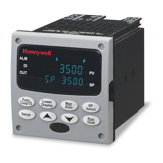
It can be enabled or disabled depending on the application or the control criteria. * The Second Current Output option is mutually exclusive with the Ethernet Communications option. † Characterizers are mutually exclusive with Setpoint Program #4. 1.2 Operator Interface Figure 1-1 UDC3500 Operator Interface UDC3500 Universal Digital Controller Product Manual 3/07... -
Page 23: Function Of Displays And Keys
Decreases setpoint or output value. Decreases Increases the configuration values or the configuration values or changes functions in changes functions in Configuration Configuration mode groups. mode groups. Infrared transceiver NEMA4X and IP66 screw attachment (each corner) 3/07 UDC3500 Universal Digital Controller Product Manual... -
Page 24: Process Instrument Explorer Software
• Create/edit configurations live, just connect software to the controller via a communications port. • Create/edit configurations offline and download to controller later via a communications port. • Communication types available on every UDC3500: Infrared (standard) RS 485 (optional) Ethernet (optional) •... -
Page 25: Figure 1-3 Depiction Of Infrared Communications
You can now communicate. After 4 minutes, the port will be shut down again. Each controller may also be assigned a different communications address. Figure 1-3 Depiction of infrared communications 3/07 UDC3500 Universal Digital Controller Product Manual... -
Page 26: Ce Conformity (Europe)
WARNING If this equipment is used in a manner not specified by the manufacturer, the protection provided by the equipment may be impaired. UDC3500 Universal Digital Controller Product Manual 3/07... -
Page 27: Installation
2 Installation 2.1 Overview Introduction Installation of the UDC3500 consists of mounting and wiring the controller according to the instructions given in this section. Read the pre-installation information, check the model number interpretation (Subsection 2.3) and become familiar with your model selections, then proceed with installation. - Page 28 Figure 2-24 Optional Electromechanical Relay Outputs Figure 2-25 Transmitter Power for 4-20 mA — 2 wire Transmitter Using Open Collector Output Figure 2-26 Transmitter Power for 4-20 mA — 2 Wire Transmitter Using Second Current Output UDC3500 Universal Digital Controller Product Manual 3/07...
-
Page 29: Condensed Specifications
• Check that the model number shown on the inside of the case agrees with what you have ordered. 2.2 Condensed Specifications Honeywell recommends that you review and adhere to the operating limits listed in Table 2-1 when you install your controller. Table 2-1 Condensed Specifications... - Page 30 Resistive Load: 5 amps @ 120 Vac or 240 Vac or 30 Vdc ϕ Inductive Load (cos = 0.4): 3 amps @ 130 Vac or 250 Vac Inductive Load (L/R = 7 milliseconds): 3.5 amps @ 30 Vdc Motor: 1/6 H.P. UDC3500 Universal Digital Controller Product Manual 3/07...
- Page 31 When applying power to more than one instrument, make sure that sufficient power is supplied. Otherwise, the instruments may not start up normally due to voltage drop from the inrush current. Weight 3 lbs. (1.3 kg) 3/07 UDC3500 Universal Digital Controller Product Manual...
- Page 32 60 ± 0.2 59 to 61 58 to 62 * The maximum moisture rating only applies up to 40 °C (104 °F). For higher temperatures, the RH specification is derated to maintain constant moisture content. UDC3500 Universal Digital Controller Product Manual 3/07...
-
Page 33: Model Number Interpretation
_ _ _ _ _ _ _ _ _ _ _ _ _ - _ _ _ _ _ KEY NUMBER - UDC3500 Single & Dual Loop Controller Description Selection Availability Digital Controller for use with 90 to 264Vac Power + Current Output #1... -
Page 34: Figure 2-1 Model Number Interpretation
English Manual (Hard Copy) French Manual (Hard Copy) Manuals German Manual (Hard Copy) Italian Manual (Hard Copy) Spanish Manual (Hard Copy) None Certificate Certificate of Conformance (F3391) TABLE VI None Figure 2-1 Model Number Interpretation UDC3500 Universal Digital Controller Product Manual 3/07... -
Page 35: Control And Alarm Relay Contact Information
Table 2-3 Alarm Relay Contact Information Unit Alarm Relay Variable NOT in Alarm State Variable in Alarm State Power Wiring Relay Indicators Relay Indicators Contact Contact N.O. Open Open N.C. Closed Closed N.O. Closed Open N.C. Open Closed 3/07 UDC3500 Universal Digital Controller Product Manual... -
Page 36: Mounting
Mounting Notes Before mounting the controller, refer to the nameplate on the outside of the case and make a note of the model number. It will help later when selecting the proper wiring configuration. UDC3500 Universal Digital Controller Product Manual 3/07... -
Page 37: Table 2-4 Mounting Procedure
(Figure 2-3). Push the point of the screw through the center piercing the elastomeric material and then tighten screws to 5 lb-in (56 N•cm). 3/07 UDC3500 Universal Digital Controller Product Manual... -
Page 38: Wiring
Vac, 42.4 Vpeak, or 60 Vdc) wiring per Permissible Wiring Bundling, Table 2-5. Electrical Noise Precautions Electrical noise is composed of unabated electrical signals, which produce undesirable effects in measurements and control circuits. UDC3500 Universal Digital Controller Product Manual 3/07... -
Page 39: Table 2-5 Permissible Wiring Bundling
• 4-20 mA output signal wiring Digital input signals • Low voltage alarm relay output wiring • Low voltage wiring to solid state type control circuits • Low voltage wiring to open collector type control circuits 3/07 UDC3500 Universal Digital Controller Product Manual... -
Page 40: Wiring Diagrams
Relay 3), enable Alarm 3 (which also uses Relay 3) and configure a Logic Gate to use Relay 3, then the instrument will use Relay #3 to perform the Time Simplex output and ignore the Alarm and Logic Gate functions. UDC3500 Universal Digital Controller Product Manual 3/07... -
Page 41: Table 2-6 Single Or Cascade Loop Controller - Loop 1 Output Functionality And Restrictions
Type, But it may be used for the Second Loop Output Type. Refer to the selection made in Table 2-7. Any current output not used as a Control Output for either loop may be used as an Auxiliary Output. 3/07 UDC3500 Universal Digital Controller Product Manual... -
Page 42: Table 2-7 Dual Loop Controller - Loop 2 Output Functionality And Restrictions
*** Current Duplex 50% is available only on Loop 1 or Loop 2, it cannot be used on both loops. If the Second Current Output is not present, then the Third Current Output is used as Loop 1 COOL output. UDC3500 Universal Digital Controller Product Manual 3/07... - Page 43 Digital Inputs Terminals. See Figure 2-23. Optional Relays Terminals (Relays 3, 4 and 5). See Figure 2-24. Optional Interface Second Current Output Terminals. See Figure 2-13. RS-485 Communications Terminals. See Figure 2-20. Ethernet Communications Terminals. See Figure 2-22. 3/07 UDC3500 Universal Digital Controller Product Manual...
- Page 44 Applying 90-264 Vac to an instrument rated for 24 Vac/dc will severely damage the instrument and is a fire and smoke hazard. damage the instrument and is a fire and smoke hazard. Figure 2-5 Mains Power Supply UDC3500 Universal Digital Controller Product Manual 3/07...
- Page 45 The millivolt values for the Thermocouple Differential Input are for a pair of J thermocouples at an ambient temperature mean of 450°F / 232°C. Cold Junction Compensation is not required for this input type. Figure 2-6 Input 1 Connections 3/07 UDC3500 Universal Digital Controller Product Manual...
- Page 46 The millivolt values for the Thermocouple Differential Input are for a pair of J thermocouples at an ambient temperature mean of 450°F / 232°C. Cold Junction Compensation is not required for this input type. Figure 2-7 Input 2 Connections UDC3500 Universal Digital Controller Product Manual 3/07...
- Page 47 450°F / 232°C. Cold Junction Compensation is not required for this input type. Input 3 is used to measure the Slidewire Input for Position Proportional Control. Figure 2-8 Input 3 Connections 3/07 UDC3500 Universal Digital Controller Product Manual...
-
Page 48: Figure 2-9 Hlai Inputs 2 And 4 Connections
These items must be installed prior to start up when the controller is wired. For 0-20 mA applications, the resistor should be located at the transmitter terminals if Burnout detection is desired. Figure 2-9 HLAI Inputs 2 and 4 Connections See Figure 2-11 for Jumper Positions. UDC3500 Universal Digital Controller Product Manual 3/07... -
Page 49: Figure 2-10 Hlai Inputs 3 And 5 Connections
Thermocouple, RTD, Volt, Millivolt, Input becomes HLAI Inputs 2 & 4 Input Types Milliamp, Radiamatic and Input becomes HLAI Inputs 3 & 5 Available (Input 3 only) Slidewire Figure 2-11 Optional Analog Input Jumper Positions 3/07 UDC3500 Universal Digital Controller Product Manual... - Page 50 The Second Current Output is mutually exclusive with Ethernet Communications. Figure 2-13 Second Current Output See Table 2-6 and Table 2-7 for other information about output types. UDC3500 Universal Digital Controller Product Manual 3/07...
-
Page 51: Figure 2-14 Output #2 - Electromechanical Relay Output
Solid State relays are rated at 1 Amp at 25°C and derated linearly to 0.5 Amp at 55°C. Customer should size fuse accordingly. Use Fast Blo fuses only. Figure 2-15 Output #2 – Solid State Relay Output See Table 2-6 and Table 2-7 for other information about output types. 3/07 UDC3500 Universal Digital Controller Product Manual... -
Page 52: Figure 2-16 Output #2 - Open Collector Output- Third
Current Output Output Load 0-20 or 4-20 mA 0 - 1000 ohms – Figure 2-17 Output #2 – Third Current Output See Table 2-6 and Table 2-7 for other information about output types. UDC3500 Universal Digital Controller Product Manual 3/07... -
Page 53: Figure 2-18 Output #2 - Dual Relay Output For Time Duplex
Figure 2-19 Output #2 – Dual Relay Output for Position Proportional or Three Position Step Control See Table 2-6 and Table 2-7 for other information about output types. See Figure 2-8 for Slidewire connections. 3/07 UDC3500 Universal Digital Controller Product Manual... -
Page 54: Figure 2-20 Rs-422/485 Communications Option Connections
Route the long wire on the Ethernet Adaptor Board over to Terminal #4 on your instrument. The RJ-45 connector on the Ethernet Adaptor Board will allow you to use a UDC3500 Universal Digital Controller Product Manual 3/07... -
Page 55: Figure 2-22 Ethernet Communications Option Without Adaptor Board
Ethernet Adaptor Board, then Figure 2-22 and Table 2-8 show the connections for a UDC to a MDI Compliant Hub or Switch utilizing a straight-through cable or for connecting a UDC to a PC utilizing a crossover cable. 3/07 UDC3500 Universal Digital Controller Product Manual... -
Page 56: Table 2-8 Terminals For Connecting A Udc To A Mdi Compliant Hub Or Switch Utilizing A Cross-Over Cable
UDC Terminal UDC Signal Name RJ45 Socket Pin # Switch Signal Name Position 4 Shield Shield Shield Position 24 RXD- TXD- Position 25 RXD+ TXD+ Position 26 TXD- RXD- Position 27 TXD+ RXD+ UDC3500 Universal Digital Controller Product Manual 3/07... -
Page 57: Table 2-9 Terminals For Connecting A Udc Directly To A Pc Utilizing A Straight-Through Cable
Use only Category 5 (STP CAT5) shielded twisted-pair Ethernet cables. Digital Input #1 Digital Input #2 Digital Input #3 Digital Input #4 Connect shield to ground at one end only. Figure 2-23 Digital Inputs 3/07 UDC3500 Universal Digital Controller Product Manual... -
Page 58: Figure 2-24 Optional Electromechanical Relay Outputs
If necessary, install a zener diode here to reduce voltage at the transmitter. A 1N4733 will reduce the voltage at the transmitter to approximately 25 Vdc. Figure 2-25 Transmitter Power for 4-20 mA — 2 wire Transmitter Using Open Collector Output UDC3500 Universal Digital Controller Product Manual 3/07... -
Page 59: Figure 2-26 Transmitter Power For 4-20 Ma - 2 Wire Transmitter Using Second Current Output
If necessary, install a zener diode here to reduce voltage at the transmitter. A 1N4733 will reduce the voltage at the transmitter to approximately 25 Vdc. Figure 2-26 Transmitter Power for 4-20 mA — 2 Wire Transmitter Using Second Current Output 3/07 UDC3500 Universal Digital Controller Product Manual... -
Page 60: Configuration
3.13 Logic Gates Set Up Group 3.14 Output Set Up Group 3.15 Input 1 Set Up Group 3.16 Input 2 Set Up Group 3.17 Input 3 Set Up Group 3.18 Input 4 Set Up Group UDC3500 Universal Digital Controller Product Manual 3/07... - Page 61 3.26 Maintenance Set Up Group 3.27 Display Set Up Group 3.28 Read Maintenance Set Up Group 3.29 Time Events Set Up Group 3.30 P.I.E. Tool Ethernet and Email Configuration Screens 3.31 Configuration Record Sheet 3/07 UDC3500 Universal Digital Controller Product Manual...
-
Page 62: Configuration Prompt Hierarchy
Segment 20 SP PROG4 PROGRAM4 STRT SEG END SEG RAMPUNIT RECYCLES HOTSTART SEG x PID* SEGxRAMP SEGxRATE* * x = 1 to 20. Program SEGx SP* SEGxTIME* SOAKxDEV concludes after Segment 20 UDC3500 Universal Digital Controller Product Manual 3/07... - Page 63 FILTER 3 BURNOUT3 EMISSIV3 INPUT4 IN4 TYPE XMITTER4 IN4 HIGH IN4 LOW RATIO 4 BIAS IN4 FILTER 4 BURNOUT4 INPUT5 IN5 TYPE XMITTER5 IN5 HIGH IN5 LOW RATIO 5 BIAS IN5 FILTER 5 BURNOUT5 3/07 UDC3500 Universal Digital Controller Product Manual...
- Page 64 HRS:MIN3 COUNTS 1 COUNTS 2 MAINTNCE COUNTS 3 TIME EVENT 1 TIME 1 HOUR 1 MINUTE 1 MONTH 1 DAY 1 EVENT 2 TIME 2 EVENT HOUR 2 MINUTE2 MONTH 2 DAY 2 UDC3500 Universal Digital Controller Product Manual 3/07...
- Page 65 Configuration Set Up Group Function Prompts CALIB USED FOR FIELD CALIBRATION STATUS VERSION FAILSAFE TESTS 3/07 UDC3500 Universal Digital Controller Product Manual...
-
Page 66: Configuration Procedure
If you do not press any keys for 30 seconds, the controller times out and reverts to the mode and associated display used prior to entry into Set Up mode. UDC3500 Universal Digital Controller Product Manual 3/07... -
Page 67: Loop 1 Tuning Set Up Group
RATE action, in minutes, affects the controller’s output whenever the deviation is changing; and affects it more when the deviation is changing faster. Also defined as “HEAT” Rate on Duplex models for variations of Heat/Cool applications. 3/07 UDC3500 Universal Digital Controller Product Manual... - Page 68 PID sets are enabled. GAIN 3 RATE3MIN 0.00 to 10.00 minutes RATE 3 MINUTES parameter is the same as previously described. This prompt appears only when four PID sets are enabled. UDC3500 Universal Digital Controller Product Manual 3/07...
- Page 69 This configuration should be copied and kept in a secure location. NOTE: The Security Code is for keyboard entry only and is not available via communications. ATTENTION Can only be changed if LOCKOUT selection is NONE. 3/07 UDC3500 Universal Digital Controller Product Manual...
- Page 70 ATTENTION Can only be viewed if LOCKOUT is configured for NONE. SP SEL SETPOINT SELECT KEY LOCKOUT—Allows you to disable the Setpoint Select key DISABLE DISABLE ENABLE ENABLE ATTENTION Can only be viewed if LOCKOUT is configured for NONE. UDC3500 Universal Digital Controller Product Manual 3/07...
-
Page 71: Loop 2 Tuning Set Up Group
RATE action, in minutes, affects the controller’s output whenever the deviation is changing; and affects it more when the deviation is changing faster. Also defined as “HEAT” Rate on Duplex models for variations of Heat/Cool applications. 3/07 UDC3500 Universal Digital Controller Product Manual... - Page 72 PID sets are enabled. GAIN 7 RATE7MIN 0.00 to 10.00 minutes RATE 7 MINUTES parameter is the same as previously described. This prompt appears only when four PID sets are enabled. UDC3500 Universal Digital Controller Product Manual 3/07...
- Page 73 PID constants. CYC6 SEC—Electromechanical relays CYC6 SX3—Solid state relays ATTENTION Cycle times are in either second or 1/3-second increments depending upon the configuration of RLY TYPE in the Output Algorithm Set Up group. 3/07 UDC3500 Universal Digital Controller Product Manual...
-
Page 74: Sp Ramp Set Up Group
Please note that the configurations used in SP Program #1 for Program End, Program State, Power Up and Key Reset affect all other SP Programs. For this reason, Program #1 must always be enabled in order to enable Programs #2, 3 and/or 4. UDC3500 Universal Digital Controller Product Manual 3/07... -
Page 75: Table 3-6 Spramp Group Function Prompts
SP Rate operates on any LSP when both DISABLE DISABLE SETPOINT RATE—Disables the setpoint SP Ramp and SP rate option. Programming are not ENABLE ENABLE SETPOINT RATE—Allows the SP rate active. feature. 3/07 UDC3500 Universal Digital Controller Product Manual... - Page 76 RAMPUNIT—Engineering Units for Ramp Segments TIME in hours: minutes TIME RATE in Engineering units per minute EU/MIN RATE in Engineering units per hour EU/HR RECYCLES 0 to 100 recycles Number of Program Recycles UDC3500 Universal Digital Controller Product Manual 3/07...
- Page 77 Ramp segment is skipped and the program will restart at the beginning of the first Soak segment in the program. ATTENTION Selection affects all enabled SP Programs. 3/07 UDC3500 Universal Digital Controller Product Manual...
- Page 78 Section 3.20 (Control 1) and Section 3.21 (Control 2). Selections are same as Same as above SEG3RAMP or SEG3RATE above. SEG3 PID SEG4 SP SEG4TIME SOAK4DEV SEG4 PID SEG5RAMP or SEG5RATE SEG5 PID SEG6 SP SEG6TIME UDC3500 Universal Digital Controller Product Manual 3/07...
- Page 79 SG15RAMP or SG15RATE SG15 PID SG16 SP SG16TIME SOAK16DEV SG16 PID SG17RAMP or SG17RATE SG17 PID SG18 SP SG18TIME SOAK18DEV SG18 PID SG19RAMP or SG19RATE SG19 PID SG20 SP SG20TIME SOAK20DEV SG20 PID 3/07 UDC3500 Universal Digital Controller Product Manual...
-
Page 80: Sp Program 2 Set Up Group
RATE in Engineering units per minute EU/MIN RATE in Engineering units per hour EU/HR ATTENTION Normally the same as Program #1 when linking programs. RECYCLES 0 to 100 recycles Number of Program Recycles UDC3500 Universal Digital Controller Product Manual 3/07... - Page 81 SEG3RAMP or Selections are same as Same as above above. SEG3RATE SEG3 PID SEG4 SP SEG4TIME SOAK4DEV SEG4 PID SEG5RAMP or SEG5RATE SEG5 PID SEG6 SP SEG6TIME SOAK6DEV SEG6 PID SEG7RAMP or SEG7RATE 3/07 UDC3500 Universal Digital Controller Product Manual...
- Page 82 SG15RAMP or SG15RATE SG15 PID SG16 SP SG16TIME SOAK16DEV SG16 PID SG17RAMP or SG17RATE SG17 PID SG18 SP SG18TIME SOAK18DEV SG18 PID SG19RAMP or SG19RATE SG19 PID SG20 SP SG20TIME SOAK20DEV SG20 PID UDC3500 Universal Digital Controller Product Manual 3/07...
-
Page 83: Sp Program 3 Set Up Group
Number of Program Recycles ATTENTION Not used when linking programs HOTSTART DISABLE HOT START—This feature allows the SP Program ENABLE to start at the current PV value rather than the current Setpoint value. 3/07 UDC3500 Universal Digital Controller Product Manual... - Page 84 Program 3 MUST be used. SEG4 SP SEG4TIME SOAK4DEV SEG4 PID SEG5RAMP or SEG5RATE SEG5 PID SEG6 SP SEG6TIME SOAK6DEV SEG6 PID SEG7RAMP or SEG7RATE SEG7 PID SEG8 SP SEG8TIME SOAK8DEV SEG8 PID UDC3500 Universal Digital Controller Product Manual 3/07...
- Page 85 SG15RAMP or SG15RATE SG15 PID SG16 SP SG16TIME SOAK16DEV SG16 PID SG17RAMP or SG17RATE SG17 PID SG18 SP SG18TIME SOAK18DEV SG18 PID SG19RAMP or SG19RATE SG19 PID SG20 SP SG20TIME SOAK20DEV SG20 PID 3/07 UDC3500 Universal Digital Controller Product Manual...
-
Page 86: Sp Program 4 Set Up Group
RAMPUNIT—Engineering Units for Ramp Segments TIME in hours: minutes TIME RATE in Engineering units per minute EU/MIN RATE in Engineering units per hour EU/HR ATTENTION Normally the same as Program #3 when linking programs. UDC3500 Universal Digital Controller Product Manual 3/07... - Page 87 Control 2 Setup Group is set to 4 KEYBD. Selections are same as Same as above SEG3RAMP or SEG3RATE above. SEG3 PID SEG4 SP SEG4TIME SOAK4DEV SEG4 PID SEG5RAMP or SEG5RATE SEG5 PID SEG6 SP SEG6TIME SOAK6DEV SEG6 PID SEG7RAMP or 3/07 UDC3500 Universal Digital Controller Product Manual...
- Page 88 SG15RAMP or SG15RATE SG15 PID SG16 SP SG16TIME SOAK16DEV SG16 PID SG17RAMP or SG17RATE SG17 PID SG18 SP SG18TIME SOAK18DEV SG18 PID SG19RAMP or SG19RATE SG19 PID SG20 SP SG20TIME SOAK20DEV SG20 PID UDC3500 Universal Digital Controller Product Manual 3/07...
-
Page 89: Accutune Set Up Group
Duplex Tuning is used when a Duplex Control Algorithm is configured. To perform a Duplex Tune, Two Local Setpoints must be configured per the Control Group in Section 3.20. See Section 4.10 for additional information. 3/07 UDC3500 Universal Digital Controller Product Manual... -
Page 90: Table 3-10 Accutune Group Function Prompts
This method should only be used after the process has lined out (stabilized). ATTENTION When SP Tune is active (T displayed) the Tuning Group parameters cannot be changed. UDC3500 Universal Digital Controller Product Manual 3/07... - Page 91 For example, if the SP range is 0 to 2400 and Setpoint change is set to 5%, then a re-tuning process will take place whenever the SP is changed by 120 or more. 3/07 UDC3500 Universal Digital Controller Product Manual...
- Page 92 CRITERA2 TUNING CRITERIA (SETPOINT ADAPTIVE) FOR LOOP 2—This prompt appears only when SP or SP+PV has been selected for Loop 2. Same selections as for Same selections as for Loop 1. Loop 1. UDC3500 Universal Digital Controller Product Manual 3/07...
- Page 93 PV has increased by more than 4% but Deadtime was not determined. AT ERR 2 Same as Loop 1. ACCUTUNE ERROR STATUS FOR LOOP 2 (Read Only) 3/07 UDC3500 Universal Digital Controller Product Manual...
-
Page 94: Algorithm Set Up Group
(hysteresis) of the on and off states of each output. Both Deadband and Hysteresis are separately adjustable. With no relay action the controller will read 50 %. ATTENTION Other prompts affected: OUT HYST and DEADBAND UDC3500 Universal Digital Controller Product Manual 3/07... - Page 95 If you select PD with Manual Reset you can also configure the following variations: • PD (Two Mode) control, • P (Single Mode) control. Set Rate (D) to 0. ATTENTION Other prompts affected: MAN RSET in the Tuning Set Up group 3/07 UDC3500 Universal Digital Controller Product Manual...
- Page 96 (loop 2) is used to adjust the remote setpoint of the secondary loop (loop 1). The output of the secondary loop is used to control the final control element. UDC3500 Universal Digital Controller Product Manual 3/07...
- Page 97 0 to 99 hours: 59 minutes or from 59 minutes: 59 seconds depending upon Period configuration). START START—Select whether the timer starts with the ALARM 2 keyboard (via the key) or via Alarm 2. Run/Hold 3/07 UDC3500 Universal Digital Controller Product Manual...
- Page 98 Alg1 = [(Input A x Ratio A + Bias A) + (K x Input B x Ratio B + Bias B)] / (1 + K)] + Alg1Bias UDC3500 Universal Digital Controller Product Manual 3/07...
- Page 99 This selection specifies the PV or SP as the higher of Input A or Input B. The following formula applies: Alg1 = higher of (Input A x Ratio A + Bias A) or (Input B x Ratio B + Bias B) 3/07 UDC3500 Universal Digital Controller Product Manual...
- Page 100 Carbon/Oxygen/Dewpoint Notes. CARB C CARBON POTENTIAL C—Make this selection if you have an A.A.C.C. type Zirconium Oxide sensor. This algorithm requires a temperature range within the region of 1500 to 1900°F. See Carbon/Oxygen/Dewpoint Notes. UDC3500 Universal Digital Controller Product Manual 3/07...
- Page 101 If the Ratio for Input 2 is set to 0.0, then a constant value may be used for the Input 2 value via the Input 2 Bias setting. When Input 2 Ratio is set to 0.0, the Input 2 low range and Sooting diagnostic messages are disabled. 3/07 UDC3500 Universal Digital Controller Product Manual...
- Page 102 LOOP 1 OUTPUT—Should not be used for Three Position Step Control applications LP2OUT LOOP 2 OUTPUT—Should not be used for Three Position Step Control applications IN AL1 INPUT ALGORITHM 1 IN AL2 INPUT ALGORITHM 2 UDC3500 Universal Digital Controller Product Manual 3/07...
- Page 103 Hydrogen content that is applicable. 590.0 to 760.0 (mm Hg) ATM PRES ATMOSPHERIC PRESSURE COMPENSATION— Used only when Relative Humidity is selected. Enter the value of the atmospheric pressure of the process. 3/07 UDC3500 Universal Digital Controller Product Manual...
- Page 104 –999. To 9999. Floating CALCULATED VARIABLE LOW SCALING (in engineering units) FACTOR FOR INPUT ALGORITHM 2—Does not apply to Feedforward algorithms. Range is used for either PV or RSP, depending upon Algorithm application. UDC3500 Universal Digital Controller Product Manual 3/07...
- Page 105 IN AL1 INPUT ALGORITHM 1 IN AL2 INPUT ALGORITHM 2 ALG2BIAS -999 to 9999 floating (in INPUT ALGORITHM 2 BIAS—Does not apply to engineering units) selections: FFWR2, FFWM2, HI SEL or LO SEL. 3/07 UDC3500 Universal Digital Controller Product Manual...
- Page 106 This is because input values outside of this range will not calculate valid %RH values. If the calculated %RH value falls below zero, the “RH LOW” diagnostic message will appear on the lower display. UDC3500 Universal Digital Controller Product Manual 3/07...
-
Page 107: Figure 3-1 Mass Flow Example
DP value by "90" to normalize the equation. (IN3 + 14.7) SCFM x 650 (IN2 + 460) Rearranging terms: (IN3 + 14.7) SCFM x 650 Example continued (IN2 + 460) on next page Constant = K Variable 22049 3/07 UDC3500 Universal Digital Controller Product Manual... - Page 108 170 F + 460 50 psi + 14.7 170 F + 460 20 psi + 14.7 110 F + 460 50 psi + 14.7 110 F + 460 20 psi + 14.7 22050 UDC3500 Universal Digital Controller Product Manual 3/07...
-
Page 109: Math Set Up Group
Xn Input values are the Output from the control algorithm, and the Yn Output is the final control element action. This application is useful for non- linear control elements or Process Variable. A simple example is shown in Figure 3-2. 3/07 UDC3500 Universal Digital Controller Product Manual... - Page 110 Y6 VALUE 0.00 to 99.99 % Y6 INPUT VALUE (Y AXIS) Y7 VALUE 0.00 to 99.99 % Y7 INPUT VALUE (Y AXIS) Y8 VALUE 0.00 to 99.99 % Y8 INPUT VALUE (Y AXIS) UDC3500 Universal Digital Controller Product Manual 3/07...
- Page 111 X14 INPUT VALUE (X AXIS) X15VALUE 0.00 to 99.99 % X15 INPUT VALUE (X AXIS) X16VALUE 0.00 to 99.99 % X16 INPUT VALUE (X AXIS) X17VALUE 0.00 to 99.99 % X17 INPUT VALUE (X AXIS) 3/07 UDC3500 Universal Digital Controller Product Manual...
- Page 112 E6 = 1 x 10 6 = 1,000,000 TOT SCR TOTALIZER RESET SECURITY LOCK—Allows the totalizer to be reset. UNLOCK UNLOCK—Allows the totalizer value to be reset. LOCK LOCK—Prevents the totalizer value from being reset. UDC3500 Universal Digital Controller Product Manual 3/07...
- Page 113 POLYNOMIAL COEFFICIENT C2 C3 X 10 –3 –9.999 to 9.999 POLYNOMIAL COEFFICIENT C3 C4 X 10 –5 –9.999 to 9.999 POLYNOMIAL COEFFICIENT C4 C5 X 10 –7 –9.999 to 9.999 POLYNOMIAL COEFFICIENT C5 3/07 UDC3500 Universal Digital Controller Product Manual...
-
Page 114: Figure 3-2 Example Of Eight Segment Characterizer
25.00 10.00 37.00 Output 20.00 55.00 from 31.00 70.00 Characterizer Characterizer 45.00 81.00 Disabled 60.00 87.00 80.00 94.50 99.99 99.99 X AXIS 100% Input to Characterizer Figure 3-2 Example of Eight Segment Characterizer UDC3500 Universal Digital Controller Product Manual 3/07... -
Page 115: Logic Gates Set Up Group
ENABLE—Enables Logic Gates Function. ATTENTION For each Logic Gate, make a selection for: Gate Type GATEnTYP Input A Source GATEnINA Input B Source GATEnINB Output Use GATEnOUT where n = 1, 2, 3, 4 or 5 3/07 UDC3500 Universal Digital Controller Product Manual... - Page 116 AND—With this gate, if Input A AND Input B are ON, then the Output will be ON; so that any single Input change will not cause the Output to change unless the other Input is already ON. INPUT A OUTPUT (Y) INPUT B UDC3500 Universal Digital Controller Product Manual 3/07...
- Page 117 X NOR EXCLUSIVE NOR)—The EXCLUSIVE NOR is an inverted EXCLUSIVE OR. If Input A and Input B are ON or OFF, the Output will be ON. INPUT A OUTPUT (Y) XNOR INPUT B 3/07 UDC3500 Universal Digital Controller Product Manual...
- Page 118 Input A will be for any of the 5 Gates you want to configure. The following selections apply if the Gate Type is OR, NOR, AND, NAND, X OR, or X NOR. UDC3500 Universal Digital Controller Product Manual 3/07...
- Page 119 2 Loops are configured. –999.0 to +9999 GATE(n) K GATE (n) K CONSTANT—This selection only (n) = 1, 2, 3, 4, or 5 appears if CONST K is configured for GATE(n)INA. 3/07 UDC3500 Universal Digital Controller Product Manual...
- Page 120 Local or Remote Setpoint – Loop 2 LR SPL2 * 0 = Local 1 = Remote Disable or Enable Adaptive Tune – Loop 2 ADAPT 2 * 0 = Disable 1 = Enable UDC3500 Universal Digital Controller Product Manual 3/07...
- Page 121 0 = Local 1 = Remote ADAPT 2 * Disable or Enable Adaptive Tune – Loop 2 0 = Disable 1 = Enable * These prompts appear only when 2 Loops are configured. 3/07 UDC3500 Universal Digital Controller Product Manual...
-
Page 122: Output Set Up Group
50 %. TIME TIME SIMPLEX—This output algorithm uses Relay1 for Time Proportional Control. Time Proportional Output has a resolution of 3.33 milliseconds with an adjustable Cycle Time (see Section 3.4). UDC3500 Universal Digital Controller Product Manual 3/07... - Page 123 % to 100 % and time is active for 0 % to 50 %. Relay controls COOL, current controls HEAT. ATTENTION Other prompts affected: OUT RNG OUT RNG CURRENT DUPLEX RANGE ALGORITHM—Used with Output Algorithm selections CUR D, CUR TI, or TI CUR. 3/07 UDC3500 Universal Digital Controller Product Manual...
- Page 124 4-20 mA output or 0-20 mA output 0-20mA operation without the need for recalibration of the controller. ATTENTION Changing the Current Output Range will result in the loss of Field Calibration values and will restore Factory Calibration values. UDC3500 Universal Digital Controller Product Manual 3/07...
- Page 125 ATTENTION Some of these configurations may not be available on Loop 2 if Loop 1 uses the available outputs. See Table 2-6 and Table 2-7 for information about output types and how they are used for each Loop. 3/07 UDC3500 Universal Digital Controller Product Manual...
- Page 126 % to 100 % and time is active for 0 % to 50 %. Relay controls COOL, current controls HEAT. ATTENTION Other prompts affected: OUT2 RNG OUT2 RNG CURRENT DUPLEX RANGE ALGORITHM—Used with Output Algorithm selections CUR D, CUR TI, or TI CUR. UDC3500 Universal Digital Controller Product Manual 3/07...
- Page 127 OUT2 ALG Parameter is configured for ATTENTION Changing the Current Output Range CURRENT, CUR D, will result in the loss of Field Calibration values and CUR TI, or TI CUR. will restore Factory Calibration values. 3/07 UDC3500 Universal Digital Controller Product Manual...
- Page 128 INPUT 3—Same as Input 1. ATTENTION Do not configure Input 3 when input 3 is used for slidewire or slidewire emulation. INPUT 4 INPUT 4—Same as Input 1. INPUT 5 INPUT 5—Same as Input 1. UDC3500 Universal Digital Controller Product Manual 3/07...
- Page 129 Deviation Display = –150 °F, which is –150 / 2000 = –7.5% of the Deviation Range, so Second Current Output = 50% – 7.5% = 42.5% which is 0.425 X 16 mA + 4 mA = 10.8 mA 3/07 UDC3500 Universal Digital Controller Product Manual...
- Page 130 (such as PID A). When using one of the characterizers, OUTPUT 2 is the output value for Loop 2 after it passes through the characterizer. CB OUTL2 is the control block output before it passes through the characterizer. UDC3500 Universal Digital Controller Product Manual 3/07...
- Page 131 LOCAL SETPOINT ONE FOR LOOP 2—Output represents Loop 2 Local Setpoint 1 regardless of active setpoint. RSP LP2 REMOTE SETPOINT FOR LOOP 2—Represents the configured Loop 2 RSP regardless of the active SetPoint for Loop 2. 3/07 UDC3500 Universal Digital Controller Product Manual...
- Page 132 For Output, this is a value in percent and can be any value between –5 % and +105 %. However, keep in mind that relay output types can only be scaled 0 % to 100 %. UDC3500 Universal Digital Controller Product Manual 3/07...
-
Page 133: Input 1 Set Up Group
0-1 V—0 to 1 Volts 0-5 V 0-5 V—0 to 5 Volts 1-5 V 1-5 V—1 to 5 Volts 0-10 V 0-10 V—0 to 10 Volts -1-1 V -1-1 V— -1 to +1 Volts 3/07 UDC3500 Universal Digital Controller Product Manual... - Page 134 12 mA = 125 Liters/Minute 20 mA = 250 Liters/Minute ATTENTION If Input 1 is selected as the PV Source, then the range of the control Setpoint will be limited by the range of units selected here. UDC3500 Universal Digital Controller Product Manual 3/07...
- Page 135 5V type that uses a dropping resistor), the dropping resistor must be remotely located (across the transmitter terminals). Otherwise, the input at the instrument terminals will always be 0 (i.e., within the normal operating range) when the sensor opens. 3/07 UDC3500 Universal Digital Controller Product Manual...
- Page 136 Radiamatic input signal that is the ratio of the actual energy emitted from the target to the energy that would be emitted if the target were a perfect radiator. Available only for Radiamatic inputs. UDC3500 Universal Digital Controller Product Manual 3/07...
-
Page 137: Input 2 Set Up Group
0-1 V—0 to 1 Volts 0-5 V 0-5 V—0 to 5 Volts 1-5 V 1-5 V—1 to 5 Volts 0-10 V 0-10 V—0 to 10 Volts -1-1 V -1-1 V— -1 to +1 Volts 3/07 UDC3500 Universal Digital Controller Product Manual... - Page 138 No filter = 0 provided for Input 2 to smooth the input signal. You can configure the first order lag time constant from 1 to 120 seconds. If you do not want filtering, enter 0. UDC3500 Universal Digital Controller Product Manual 3/07...
- Page 139 Radiamatic input signal that is the ratio of the actual energy emitted from the target to the energy that would be emitted if the target were a perfect radiator. Available only for Radiamatic inputs. 3/07 UDC3500 Universal Digital Controller Product Manual...
-
Page 140: Input 3 Set Up Group
0-1 V—0 to 1 Volts 0-5 V 0-5 V—0 to 5 Volts 1-5 V 1-5 V—1 to 5 Volts 0-10 V 0-10 V—0 to 10 Volts -1-1 V -1-1 V— -1 to +1 Volts UDC3500 Universal Digital Controller Product Manual 3/07... - Page 141 No filter = 0 provided for Input 3 to smooth the input signal. You can configure the first order lag time constant from 1 to 120 seconds. If you do not want filtering, enter 0. 3/07 UDC3500 Universal Digital Controller Product Manual...
- Page 142 Radiamatic input signal that is the ratio of the actual energy emitted from the target to the energy that would be emitted if the target were a perfect radiator. Available only for Radiamatic inputs. UDC3500 Universal Digital Controller Product Manual 3/07...
-
Page 143: Input 4 Set Up Group
INPUT 4 HIGH RANGE VALUE—This value in (in engineering units) engineering units is displayed for all inputs but can only be changed for inputs configured for linear or square root transmitter characterization. See the example in IN1 HI. 3/07 UDC3500 Universal Digital Controller Product Manual... - Page 144 UPSCALE BURNOUT—Forces the Input 4 signal to the full-scale value when the sensor fails. Diagnostic message IN4 FAIL intermittently flashed on the lower display. The controller remains in Automatic control mode and adjusts the controller output signal accordingly. UDC3500 Universal Digital Controller Product Manual 3/07...
- Page 145 Burnout current. (For this selection, no burnout signal is sent to the sensor.) ATTENTION The Thermocouple Health feature is disabled when NO FS is configured. 3/07 UDC3500 Universal Digital Controller Product Manual...
-
Page 146: Input 5 Set Up Group
INPUT 5 HIGH RANGE VALUE—This value in (in engineering units) engineering units is displayed for all inputs but can only be changed for inputs configured for linear or square root transmitter characterization. See the example in IN1 HI. UDC3500 Universal Digital Controller Product Manual 3/07... - Page 147 UPSCALE BURNOUT—Forces the Input 5 signal to the full-scale value when the sensor fails. Diagnostic message IN5 FAIL intermittently flashed on the lower display. The controller remains in Automatic control mode and adjusts the controller output signal accordingly. 3/07 UDC3500 Universal Digital Controller Product Manual...
- Page 148 Burnout current. (For this selection, no burnout signal is sent to the sensor.) ATTENTION The Thermocouple Health feature is disabled when NO FS is configured. UDC3500 Universal Digital Controller Product Manual 3/07...
-
Page 149: Control Set Up Group
Digital Inputs. Press the key until you see PID SET1 Lower/Display or PID SET2 then press to switch between sets. Configure the values for: Gain, Rate, Reset Gain #2, Rate #2, Reset #2 3/07 UDC3500 Universal Digital Controller Product Manual... - Page 150 Similarly, the controller switches between the other PID sets based upon the values configured for SW VAL 2 and SW VAL 3. ATTENTION Other prompts affected: SW VALUE, SW VAL 2 and SW VAL 3. UDC3500 Universal Digital Controller Product Manual 3/07...
- Page 151 Similarly, the controller switches between the other PID sets based upon the values configured for SW VAL 2 and SW VAL 3. ATTENTION Other prompts affected: SW VALUE, SW VAL 2 and SW VAL 3. 3/07 UDC3500 Universal Digital Controller Product Manual...
- Page 152 FOUR LOCAL SETPOINTS—This selection lets you switch between four local setpoints using the SP/Select RSP SRC REMOTE SETPOINT SOURCE—This selection determines what your remote setpoint source will be when toggled by the key or Digital Input. SP/Select UDC3500 Universal Digital Controller Product Manual 3/07...
- Page 153 MANUAL, LSP—At power-up, the controller will use manual mode with the local setpoint displayed. A LSP AUTOMATIC MODE, LAST LSP—At power-up, the controller will use automatic mode with the last local setpoint used before power down displayed. 3/07 UDC3500 Universal Digital Controller Product Manual...
- Page 154 ACTION CONTROL OUTPUT DIRECTION—Select direct or reverse output action. DIRECT DIRECT ACTING CONTROL—The controller’s output increases as the process variable increases. REVERSE REVERSE ACTING CONTROL—The controller’s output decreases as the process variable increases. UDC3500 Universal Digital Controller Product Manual 3/07...
- Page 155 (positive value) or both outputs operate (negative value). –5.0 to 25.0 % Time Duplex 0.0 to 25.0 % On-Off Duplex 0.5 to 5.0 % Position Proportional and Three Position Step 3/07 UDC3500 Universal Digital Controller Product Manual...
- Page 156 (NOTE 1) PBorGAIN PROPORTIONAL BAND UNITS—Select one of the (selection is used for following for the Proportional (P) term of the PID both loops) algorithm: UDC3500 Universal Digital Controller Product Manual 3/07...
- Page 157 Math A, Math B, Math C or Math D; then the SP HiLIM and SP LoLIM values can be set anywhere between –999 and 9999 and are not limited to the CALC HI and CALC LOW values 3/07 UDC3500 Universal Digital Controller Product Manual...
-
Page 158: Control 2 Set Up Group
Digital Inputs. Press key until you see PID SET3 or Lower/Display PID SET4 then press or to switch between UDC3500 Universal Digital Controller Product Manual 3/07... - Page 159 Similarly, the controller switches between the other PID sets based upon the values configured for SW VAL 2 and SW VAL 3. ATTENTION Other prompts affected: SW VALUE, SW VAL 2 and SW VAL 3. 3/07 UDC3500 Universal Digital Controller Product Manual...
- Page 160 Similarly, the controller switches between the other PID sets based upon the values configured for SW VAL 2 and SW VAL 3. ATTENTION Other prompts affected: SW VALUE, SW VAL 2 and SW VAL 3. UDC3500 Universal Digital Controller Product Manual 3/07...
- Page 161 INPUT 4—Remote Setpoint using Input 4. INPUT 3 INPUT 5—Remote Setpoint using Input 5. INPUT 4 INPUT ALGORITHM 1—Remote Setpoint using INPUT 5 Input Algorithm 1. IN AL1 INPUT ALGORITHM 2—Remote Setpoint using Input Algorithm 2. 3/07 UDC3500 Universal Digital Controller Product Manual...
- Page 162 Local Setpoint used before power down displayed. A RSP AUTOMATIC MODE, LAST RSP—At power-up, the controller will use automatic mode with the last Remote Setpoint used before power down displayed. UDC3500 Universal Digital Controller Product Manual 3/07...
- Page 163 HIGH OUTPUT LIMIT—This is the highest value of output beyond which you do not want the controller automatic output to exceed. 0 % to 100 % For relay output types. –5 % to 105 % For current output types 3/07 UDC3500 Universal Digital Controller Product Manual...
- Page 164 Math A, Math B, Math C or Math D, then the SP HiLIM and SP LoLIM values can be set anywhere between –999 and 9999 and are not limited to the CALC HI and CALC LOW values. UDC3500 Universal Digital Controller Product Manual 3/07...
-
Page 165: Options Set Up Group
Second Current Output or Third Current Output to be a specific selection with desired scaling. The UDC3500 has three current outputs, two of which are configured in this Set Up Group. The UDC3500 has four digital inputs. Loop assignments are made in this Set Up Group. - Page 166 Deviation Display = –150 °F, which is –150 / 2000 = –7.5% of the Deviation Range, so Second Current Output = 50% – 7.5% = 42.5% which is 0.425 X 16 mA + 4 mA = 10.8 mA UDC3500 Universal Digital Controller Product Manual 3/07...
- Page 167 (such as PID A). When using one of the characterizers, OUTPUT 2 is the output value for Loop 2 after it passes through the characterizer. CB OUTL2 is the control block output before it passes through the characterizer. 3/07 UDC3500 Universal Digital Controller Product Manual...
- Page 168 LOCAL SETPOINT ONE FOR LOOP 2—Output represents Loop 2 Local Setpoint 1 regardless of active setpoint. RSP LP2 REMOTE SETPOINT FOR LOOP 2—Represents the configured Loop 2 RSP regardless of the active SetPoint for Loop 2. UDC3500 Universal Digital Controller Product Manual 3/07...
- Page 169 4-20mA output or 0-20mA 0-20mA output operation without the need for recalibration of the instrument. ATTENTION Changing the Current Output Range will result in the loss of Field Calibration values and will restore Factory Calibration values. 3/07 UDC3500 Universal Digital Controller Product Manual...
- Page 170 TO 3SP puts the controller into local setpoint 3. TO LOCAL SETPOINT FOUR—Contact closure TO 4SP puts the controller into local setpoint 4. TO DIRECT ACTION—Contact closure selects TO DIR direct controller action. UDC3500 Universal Digital Controller Product Manual 3/07...
- Page 171 Program. Upper left character blinks “R”. Reopening the contact has no effect. This selection applies to either loop. ATTENTION When multiple SP Programs are enabled, this configuration is affected by the “SPP A” and “SPP B” configurations below. 3/07 UDC3500 Universal Digital Controller Product Manual...
- Page 172 Digital Inputs assigned to Loop 2 will also use the AUTO OUT value in the Control Setup Group. ATTENTION Does not apply to Three Position Step Control. TIMER—Contact closure starts timer, if enabled. TIMER Reopening the switch has no effect. UDC3500 Universal Digital Controller Product Manual 3/07...
- Page 173 LOOP DISPLAY—Contact closure displays the loop D L1/2 not currently being displayed. Opening contact returns to the original loop display. EXTERNAL RESET FEEDBACK—Contact closure RST FB allows Input 2 to override the internal reset value. 3/07 UDC3500 Universal Digital Controller Product Manual...
- Page 174 PV is frozen at last value. When switch opens, PV resumes normal operation after 2 seconds. Digital Input SOFTWARE OPTIONS DIGITAL INPUTS—The prompts for following Digital Input selections appear only when the Healthwatch Software Option is installed. Software Options UDC3500 Universal Digital Controller Product Manual 3/07...
- Page 175 PLUS DIRECT ACTION—Contact closure selects +TO DIR direct controller action. PLUS SETPOINT 2—Contact closure puts the +TO SP2 controller to Local Setpoint 2. PLUS DISABLE ADAPTIVE TUNE—Contact +DIS AT closure disables Accutune process. 3/07 UDC3500 Universal Digital Controller Product Manual...
- Page 176 TO RUN, TO HOLD, RERUN, or To BEGIN will control the setpoint program regardless of the loop to which the Digital Input is assigned. UDC3500 Universal Digital Controller Product Manual 3/07...
-
Page 177: Communications Set Up Group
ATTENTION If there are no IR communications transactions for four minutes, then the IR port automatically shuts down. It can be re-enabled at any time by pressing any key on the front panel. 3/07 UDC3500 Universal Digital Controller Product Manual... - Page 178 LEVEL—Determines the mode of local control you want when the controller is shed from the communications link. LAST—SAME MODE LAST The controller will return to the same mode (manual or automatic) that it had before shed. UDC3500 Universal Digital Controller Product Manual 3/07...
- Page 179 –20.0 to 20.0 CSP2RATO LOOP 2 COMPUTER SETPOINT RATIO— Computer setpoint ratio for Loop 2. –999. to 9999. CSP2BIAS LOOP 2 COMPUTER SETPOINT BIAS—Computer (engineering units) setpoint bias in Engineering Units for Loop 2. 3/07 UDC3500 Universal Digital Controller Product Manual...
- Page 180 Loopback test at a time, as the instrument running the Loopback test transmits on the RS-485 bus. The host computer should not be transmitting on the link while the Loopback test is active. UDC3500 Universal Digital Controller Product Manual 3/07...
-
Page 181: Alarms Set Up Group
Configuration 3.24 Alarms Set Up Group Introduction The UDC3500 has four alarms and eight alarm setpoints. Each alarm has its own hysteresis configuration. An alarm is an indication that an event that you have configured (for example—Process Variable) has exceeded one or more alarm limits. There are up to four alarms available. -
Page 182: Table 3-24 Alarms Group Function Prompts
REMOTE SETPOINT – LOOP 2 FSAFE 2 ALARM ON FAILSAFE – LOOP 2 PVRATE2 PV RATE OF CHANGE – LOOP 2 BREAK 2 LOOP BREAK – LOOP 2 (NOTE 4) PV2HOLD PV HOLD – LOOP 2 UDC3500 Universal Digital Controller Product Manual 3/07... - Page 183 Totalizer Scale Factor: *E4 = 1 x 10 = 10,000 Alarm Type: Totalizer Alarm SP: 400 Alarm High / Low: HIGH Alarm will activate when the Totalizer Value exceeds 400 x 10 = 4,000,000. 3/07 UDC3500 Universal Digital Controller Product Manual...
- Page 184 Alarm Type is configured for Event On/Off: A1S1 EV ALARM 1 SEGMENT EVENT 1—Select whether you want the alarm type chosen in prompt A1S1TYPE to alarm the beginning or end of a segment in setpoint Ramp/Soak programming. UDC3500 Universal Digital Controller Product Manual 3/07...
- Page 185 Same as A1S1 VAL ALARM 2 SETPOINT 1 VALUE—Same as A1S1 VAL. HIGH A2S1 H L ALARM 2 SETPOINT 1 STATE—Same as A1S1 H L. A2S1 EV BEGIN ALARM 2 SEGMENT EVENT 1—Same as A1S1 3/07 UDC3500 Universal Digital Controller Product Manual...
- Page 186 (OR condition). See Section 3.29. ATTENTION Not applicable with Relay Duplex or Position Proportional output types unless using Dual Relay PWA. Same as A1S1 VAL A3S2 VAL ALARM 3 SETPOINT 2 VALUE—Same as A1S1 VAL. UDC3500 Universal Digital Controller Product Manual 3/07...
- Page 187 ALARM HYSTERESIS FOR ALARM 4—Same as 0.0 to 100.0 % of span or ALHYST4 ALHYST1. full output as appropriate ALM OUT1 LATCHING ALARM OUTPUT 1—Alarm output 1 can be configured to be Latching or Non-latching. 3/07 UDC3500 Universal Digital Controller Product Manual...
- Page 188 ENABLE message will appear on the lower display whenever an alarm is active. This message can be disabled by pressing the RUN/HOLD key, similar to other diagnostic messages. See Section 7.5 for messages. UDC3500 Universal Digital Controller Product Manual 3/07...
-
Page 189: Real Time Clock Set Up Group
+10.7 seconds per month. Each negative increment represents a clock change of –5.35 seconds per month. These values correspond to a total adjustment range of between +5.5 and –2.75 minutes per month. 3/07 UDC3500 Universal Digital Controller Product Manual... -
Page 190: Maintenance Set Up Group
DIGITAL INPUT 2—Cumulative time Digital Input 2 was closed DIGIN3 DIGITAL INPUT3—Cumulative time Digital Input 3 was closed DIGIN4 DIGITAL INPUT 4—Cumulative time Digital Input 4 was closed MANUAL2 LOOP 2 MANUAL—Cumulative time Loop 2 was in Manual. UDC3500 Universal Digital Controller Product Manual 3/07... - Page 191 GUAR SK GUARANTEED SOAK—Number of times unit has been in guaranteed soak. PWRCYC POWER CYCLE—Number of times unit’s power has cycled off and on. PVRANGE LOOP 1 PV RANGE—Number of times Loop 1’s PV 3/07 UDC3500 Universal Digital Controller Product Manual...
- Page 192 COUNTER 1 will be reset COUNT 1 COUNTER 2 will be reset COUNT 2 COUNTER 3 will be reset COUNT 3 ALL COUNTERS will be reset ALL CNT ALL T+C ALL TIMERS AND COUNTERS will be reset UDC3500 Universal Digital Controller Product Manual 3/07...
-
Page 193: Display Set Up Group
DEG C DEG C—Degrees Centigrade – Degrees C Annunciator lighted NONE NONE—No temperature annunciators lighted. Upper and Lower Displays will show temperature in Degrees Fahrenheit when inputs are configured for Thermocouple or RTD types. 3/07 UDC3500 Universal Digital Controller Product Manual... - Page 194 DISABLE—Disable Diagnostic Messages IDNUMBER 0 to 255 IDENTIFICATION NUMBER—This configuration is used only for uniquely identifying a particular controller over a communications network. The value selected has no effect on how the controller operates. UDC3500 Universal Digital Controller Product Manual 3/07...
-
Page 195: Read Maintenance Set Up Group
Shows the value of Counter 1. COUNTS 1 for output relays 1 to 5) COUNTS 2 Same as COUNTS 1 Shows the value of Counter 2. Same as COUNTS 1 Shows the value of Counter 3. COUNTS 3 3/07 UDC3500 Universal Digital Controller Product Manual... -
Page 196: Time Events Set Up Group
DAY—Day of Month or Week 1 to 31 When “CALENDR” is configured: Day of the month (NOTE 5) 1 to 7 When “DAYofWK” is configured: Day of the week (Sunday = 1, Saturday = 7) (NOTE 4) UDC3500 Universal Digital Controller Product Manual 3/07... - Page 197 NOTE 5: The range of DAY 1 or DAY 2 is restricted based upon the MONTH 1 or MONTH 2 selection. For example, a selection of APRIL for the MONTH 1 configuration will restrict the DAY 1 configuration to a range of 1 to 30. NOTE 6: Only operates on SP Program #1. 3/07 UDC3500 Universal Digital Controller Product Manual...
-
Page 198: Tool Ethernet And Email Configuration Screens
These settings can be changed via the Ethernet Configuration Screen as shown in Figure 3-3. See Section 4.32 – Configuring your Ethernet Connection for more information. Figure 3-3 Ethernet Configuration Screen UDC3500 Universal Digital Controller Product Manual 3/07... -
Page 199: Figure 3-4 Email Configuration Screen
Email server, then the SMTP IP Address may generally be found by opening a DOS shell and typing: ping smtp.[your domain name and extension, i.e., “yourisp.com”] 3/07 UDC3500 Universal Digital Controller Product Manual... - Page 200 Real Time Clock option will send Email time-stamped with the current time in the controller. If the SMTP address on your network is changed, such as can happen when a server is replaced, then you must reconfigure the Email SMTP IP address in this instrument to match. UDC3500 Universal Digital Controller Product Manual 3/07...
-
Page 201: Configuration Record Sheet
For SP Program #1 record sheet – see Figure 4-8 PROGRAM2 DISABLE PROGRAM2 For SP Program #2 record sheet – see Figure 4-9 PROGRAM3 PROGRAM3 DISABLE For SP Program #3 record sheet – see Figure 4-10 3/07 UDC3500 Universal Digital Controller Product Manual... - Page 202 ALG 1 INB ALG1 INC PCO SEL DISABLE PCT CO 0.200 PCT H2 ATM PRESS 780.0 ALG1 BIAS INALG2 NONE MATH K2 CALC HI CALC LOW ALG2 INA ALG2 INB ALG2 INC ALG2 BIAS UDC3500 Universal Digital Controller Product Manual 3/07...
- Page 203 Y17 VALUE TOTALIZE DISABLE ΣXXXXXXX TOT SCALE TOT SCR UNLOCK Σ RESET? TOT RATE SECOND POLYNOM DISABLE C0 VALUE C1 VALUE C2 X 10 C2 X 10 C2 X 10 C2 X 10 3/07 UDC3500 Universal Digital Controller Product Manual...
- Page 204 RATIO 1 1.00 BIAS IN1 FILTER 1 BURNOUT1 NONE EMISSIV1 0.00 IN2 TYPE 0-10mV INPUT 2 XMITTER2 LINEAR IN2 HIGH 1000 IN2 LOW RATIO 2 1.00 BIAS IN2 FILTER 2 BURNOUT2 NONE EMISSIV2 0.00 UDC3500 Universal Digital Controller Product Manual 3/07...
- Page 205 REVERSE OUT RATE DISABLE PCT/M UP PCT/M DN OUTHiLIM OUTLoLIM I Hi LIM I Lo LIM DROPOFF DEADBAND OUT HYST FAILMODE NO LATCH FAILSAFE SW FAIL MAN OUT AUTO OUT PBorGAIN GAIN MINorRPM 3/07 UDC3500 Universal Digital Controller Product Manual...
- Page 206 NONE Com ADDR ComSTATE DISABLE IR ENABLE DISABLE BAUD 19200 TX DELAY WSFLOAT FP B SHEDENAB DISABLE SHEDTIME SHEDMODE LAST SHEDSP TO LSP UNITS PERCENT CSP RATO CSP BIAS CSP2RATO CSP2BIAS LOOPBACK DISABLE UDC3500 Universal Digital Controller Product Manual 3/07...
- Page 207 “ “ “ SET CLK? “ “ “ “ ADJUST TIME 1 DISABLE MAINTNCE TIME 2 DISABLE TIME 3 DISABLE COUNT 1 DISABLE COUNT 2 DISABLE COUNT 3 DISABLE PASSWORD RES TYPE NONE 3/07 UDC3500 Universal Digital Controller Product Manual...
- Page 208 ETHERNET AND EMAIL IP Address 10.0.0.2 (Accessible via PIE Subnet Mask 255.255.255.0 Tool) Default Gateway 0.0.0.0 SMTP Address (for Outgoing) 0.0.0.0 To Email 1 From Email 1 To Email 2 From Email 2 UDC3500 Universal Digital Controller Product Manual 3/07...
-
Page 209: Monitoring And Operating The Controller
4.21 Alarm Setpoints 4.22 Three Position Step Control Algorithm 4.23 Setting a Failsafe Output Value for Restart after a Power Loss 4.24 Setting Failsafe Mode 4.25 Carbon Potential, Oxygen and Dewpoint Algorithms 4.26 Healthwatch 3/07 UDC3500 Universal Digital Controller Product Manual... -
Page 210: Operator Interface
NONE. Thereafter, that selected number must be used to change the lockout level from something other than NONE. Write the number on the Configuration Record Sheet in the configuration ATTENTION section so you will have a permanent record. UDC3500 Universal Digital Controller Product Manual 3/07... -
Page 211: Lockout Feature
Timer, Tuning, and SP Ramp are Read only. No other parameters are viewable. See Subsection 3.4 - Tuning Parameters Set Up Group prompts to select one of the above. Security Code (see Subsection 4.3) 3/07 UDC3500 Universal Digital Controller Product Manual... - Page 212 When a key is pressed and the prompt “Key Error” appears in the lower display, it will be for one of the following reasons: • Parameter not available or locked out • Not in setup mode, press key first SET UP • Individual key locked out. UDC3500 Universal Digital Controller Product Manual 3/07...
-
Page 213: Monitoring Your Controller
I—Cascade control (when Loop 1 is displayed) C—Computer setpoint active O—Output override active H—Setpoint Ramp or Setpoint Program in HOLD mode R—Setpoint Ramp or Setpoint Program in RUN mode H and R alternating—Guaranteed Soak in operation 3/07 UDC3500 Universal Digital Controller Product Manual... -
Page 214: Viewing The Operating Parameters
Digital Input Selections “PROG LO” and “PROG HI” override the keyboard and force the Program selection per their status (open or closed). When running linked programs, the Setpoint Program Number can be incremented/decremented when in the “HOLD” mode. UDC3500 Universal Digital Controller Product Manual 3/07... -
Page 215: Diagnostic Messages
LOWER DISPLAY key. If the underlying condition has not been corrected, then the next time the instrument is powered-down/powered-up, the diagnostic message will return. 3/07 UDC3500 Universal Digital Controller Product Manual... -
Page 216: Start Up Procedure For Operation
Refer to Tuning Set Up group to ensure that the selections for Pb or GAIN, RATE T, and I MIN, or I RPM have been entered. Use Accutune to tune the controller; see the procedure in this section. UDC3500 Universal Digital Controller Product Manual 3/07... -
Page 217: Control Modes
In Automatic cascade mode, there are two control loops, with one loop’s output acting as the AUTOMATIC setpoint for the second control loop. There is only one physical output in this mode. CASCADE 3/07 UDC3500 Universal Digital Controller Product Manual... -
Page 218: What Happens When You Change Modes
If LSP tracking is not configured, the local setpoint will not be altered when the transfer is made. 4.8 Setpoints Introduction You can configure the following setpoints for the UDC3500 controller. • One to four Local Setpoints • One to four Local Setpoints plus one Remote Setpoint Refer to Subsection 3.20 –... -
Page 219: Table 4-7 Procedure For Changing The Local Setpoints
• you attempt to change the setpoint while a setpoint ramp is enabled, or • if you attempt to change the setpoint with the setpoint select function key disabled. Appears to the left of the active setpoint 3/07 UDC3500 Universal Digital Controller Product Manual... -
Page 220: Timer
Alarm 1 relay. At “TIME-OUT: • Alarm 1 is active • The clock character has stopped moving • The Time display shows either 00:00 or the time-out period depending on the configuration selection UDC3500 Universal Digital Controller Product Manual 3/07... -
Page 221: Accutune Iii
If the controller determines that the process has appreciable dead time, it will automatically default to use Dahlin Tuning, which produces very conservative tuning constants. The SLOW selection may be useful for TPSC and 3/07 UDC3500 Universal Digital Controller Product Manual... - Page 222 Tuning group, and begins PID control with the correct tuning parameters. This works with any process, including integrating type processes, and allows retuning at a fixed setpoint. UDC3500 Universal Digital Controller Product Manual 3/07...
-
Page 223: Tune For Simplex Outputs
“NO TUNE” prompt. ATTENTION The Accutune process may be aborted at any time by changing the lower display back to “NoTUNE” or by switching the controller into Manual Mode. 3/07 UDC3500 Universal Digital Controller Product Manual... -
Page 224: Tune For Duplex (Heat/Cool)
PID SET 2. Configuration Check for Duplex See Subsection 3.10 – Accutune Set Up Group for details. Make sure: • TUNE has been enabled • DUPLEX has been configured to Manual, Automatic or Disabled UDC3500 Universal Digital Controller Product Manual 3/07... -
Page 225: Using Automatic Tune At Start-Up For Duplex (Heat/Cool)
Tuning in operation Lower Upper display will show a “T” as Display long as ACCUTUNE process is operating. When process completes, tuning parameters are calculated and lower display will show “NO TUNE” prompt. 3/07 UDC3500 Universal Digital Controller Product Manual... -
Page 226: Using Blended Tune At Start-Up For Duplex (Heat/Cool)
Tuning in operation Lower Upper display will show a “T” as Display long as ACCUTUNE process is operating. When process completes, tuning parameters are calculated and lower display will show “NO TUNE” prompt. UDC3500 Universal Digital Controller Product Manual 3/07... -
Page 227: Using Manual Tune At Start-Up For Duplex (Heat/Cool)
Tuning in operation Upper display will show a “T” as Lower Display long as ACCUTUNE process is operating. When process completes, tuning parameters are calculated and lower display will show “NO TUNE” prompt. 3/07 UDC3500 Universal Digital Controller Product Manual... -
Page 228: Accutune Error Codes
Output insufficient to get to SP value. ATTENTION This error will cause the controller to switch from Automatic to Manual Mode. The output is then set to the value present at the beginning of UDC3500 Universal Digital Controller Product Manual 3/07... -
Page 229: Fuzzy Overshoot Suppression
Enabled or Disabled as required by the application to work with the Accutune algorithm. Fuzzy Tune should not be enabled for processes that have an appreciable amount of deadtime. Configuration To configure this item, refer to Section 3 – Configuration: 3/07 UDC3500 Universal Digital Controller Product Manual... -
Page 230: Using Two Sets Of Tuning Constants
To select the type of function. Available selections are: Function 1 ONLY—1 set of constants 2KEYBD—2 sets, keyboard selectable 2PV SW—2 sets, auto switch at PV value 2SP SW—2 sets, auto switch at SP value UDC3500 Universal Digital Controller Product Manual 3/07... -
Page 231: Table 4-17 Procedure For Switching Pid Sets From The Keyboard
Upper Display = (the PV value) Lower Display = PIDS X (X= 1 or 2) To change PID SET 1 to PID SET2 or Vice Versa. You can use Accutune on each set. To accept changes. Lower Display 3/07 UDC3500 Universal Digital Controller Product Manual... -
Page 232: Input Math Algorithms
Relative Humidity Summer Hi Select Lo Select √ Multiply Divide √ Multiply Multiply Divide Multiply Feedforward Multiplier Carbon Potential (several types) Oxygen Dewpoint The formulas for these selections are given in Section 3.11. UDC3500 Universal Digital Controller Product Manual 3/07... - Page 233 Alarm on totalizer value The alarm type configuration includes an Alarm on Totalizer value. This allows an alarm setpoint value to be used to cause an alarm when exceeded. The alarm setpoint represents 3/07 UDC3500 Universal Digital Controller Product Manual...
-
Page 234: Logic Gate Operation
The rules and regulations regarding the use of the logic gates are listed in . UDC3500 Universal Digital Controller Product Manual 3/07... - Page 235 Monitoring and Operating the Controller Table 4-18. 3/07 UDC3500 Universal Digital Controller Product Manual...
-
Page 236: Table 4-18 Logic Gates Constraints And Dynamic Operation Status
Local/Remote Setpoint, then pushing the key or Man/Auto key, respectively, will result in a key error SP Select diagnostic display. However, the key is permitted during Man/Auto communications when the Host computer has mode control. UDC3500 Universal Digital Controller Product Manual 3/07... -
Page 237: Digital Input Option (Remote Switching)
Suspends setpoint program or setpoint ramp operation. Contact open runs the ramp/program from the Hold point unless the Ramp/Program was not previously started via the key. Run/Hold This selection applies to either loop. 3/07 UDC3500 Universal Digital Controller Product Manual... - Page 238 Allows Output 2 to override Output 1. blinks Puts the controller into Remote Setpoint. When contact opens, TO RSP SP annunciator blinks the controller returns to former operation, local or remote Lower display shows setpoint. UDC3500 Universal Digital Controller Product Manual 3/07...
- Page 239 Reset Healthwatch Counter 2 to zero. REST C2 Reset Healthwatch Counter 3 to zero. REST C3 R ALL C Reset all Healthwatch Counters to zero. R ALLTC Reset all Healthwatch Timers and Counters to zero. 3/07 UDC3500 Universal Digital Controller Product Manual...
-
Page 240: Table 4-20 Digital Input Combinations "Dig In1" Or "Dig In2
Action Disabled means that the digital input or digital combination parameter is configured but the action cannot occur when the digital input is active because the selected parameter is disabled. UDC3500 Universal Digital Controller Product Manual 3/07... -
Page 241: Table 4-21 Digital Inputs 1 And 2 Combination
DIG IN1 = ToPID2 action will occur. DIG1 COM = +ToSP2 PID SETS = 2KEYBD LSP’S =TWO Instrument is correctly configured for both actions and thus will perform as desired when DIG IN1 is active. 3/07 UDC3500 Universal Digital Controller Product Manual... -
Page 242: Auto/Manual Station
– SP = 2SP Output – PV = IN2 – PIDSET2 SP1 = PIDSET1 selection same OUT1 OUT1 Output 1 4-20 mA To valve Figure 4-2 Auto/Manual Station for Loop 1 (Loop 2 similar) UDC3500 Universal Digital Controller Product Manual 3/07... -
Page 243: Table 4-22 Auto/Manual Station Mode Configuration Procedure
Input 1 is typically the PV of some upper controller and Input 2 is typically that controller’s output. If the upper control fails, the upper device or some watchdog opens the digital input switch and UDC3500 back-up PID A control is active. When the upper control reactivates, the digital input switch is closed and the Auto/Manual Station becomes a repeater station and allows the upper control output signal to pass through. - Page 244 Until you see: Func Loop 1/2 Algorithm Upper Display = (available selections) Lower Display = CONT ALG To select: Select PID A PID A— PID A This is defining the back-up control algorithm. UDC3500 Universal Digital Controller Product Manual 3/07...
- Page 245 • In the ALGORTHM set up list, do not select CONT ALG as PID B, ON-OFF, or 3PSTEP. • In the Display menu when PIDSET # is displayed, DO NOT change the selection. 3/07 UDC3500 Universal Digital Controller Product Manual...
-
Page 246: Two Loops Of Control
Current output on Loop 2 requires that either Second Current Output or Third Current Output be installed. • Loop 2 relay output is always dedicated to relay outputs 3 and 4. • No Three Position Step output on Loop 2. UDC3500 Universal Digital Controller Product Manual 3/07... -
Page 247: Figure 4-3 Functional Overview Block Diagram Of A Single Loop (Loop #1) Or Dual Loop Controller (Loop #1 And Loop #2)
The following rules apply for internal Cascade control: • Loop 2 is the primary (external) loop. • Loop 1 is the secondary (internal or slave) loop. • Loop 1 Remote Setpoint is fixed as the Loop 2 output. 3/07 UDC3500 Universal Digital Controller Product Manual... -
Page 248: Figure 4-4 Functional Overview Block Diagram Of Internal Cascade Controller
This tracking is done in the direction opposite to the Override Select configuration; i.e., for High Select, the unselected output tracks within 5 % of the lower output, and vice versa for Low Select. UDC3500 Universal Digital Controller Product Manual 3/07... -
Page 249: Configuring Two Loops Of Control
Upper Display =SET Lower Display = ALGORTHM Select the PID Until you see: Func Loop 1/2 Loops Upper Display = (available selections) Lower Display = PIDLOOPS To change selection To accept changes. Lower Display 3/07 UDC3500 Universal Digital Controller Product Manual... -
Page 250: Monitoring Two Loops Of Control
RSP appears in the lower display then release the key to select remote SP Select setpoint. Switching between automatic and manual mode on either loop will not affect the internal Cascade indication. UDC3500 Universal Digital Controller Product Manual 3/07... -
Page 251: Operating Two Loops Of Control
Output 1 and Output 2 (Lo Select) to appear at Output 1 terminals to drive the final control element. Refer to Section 5.12 for Override rules and block diagram. Override prompts appear under the Algorithm Set Up group, function prompt OUT OVRD. 3/07 UDC3500 Universal Digital Controller Product Manual... -
Page 252: Alarm Setpoints
- - - - - - - - - - - - - - - - - - - - - - - - - - - - - A4S2 VAL = Alarm 4, Setpoint 2 Value NOTES: With Three position step control, alarms set for “output” will not function. MANUAL, RSP, and F’SAFE selections do not have setpoint values. UDC3500 Universal Digital Controller Product Manual 3/07... - Page 253 Event (A1S1 EV) is configured for END, then this alarm will deactivate when the Setpoint Program reaches the end of Segment 5. ATTENTION Some other alarm configuration must first turn the alarm on before this configuration can turn it off. 3/07 UDC3500 Universal Digital Controller Product Manual...
-
Page 254: Three Position Step Control Algorithm
POS XX.X. The TPSC algorithm does not use this value; it is only used for display purposes. The slidewire must be calibrated for this display to operate correctly. See Section 6.5. UDC3500 Universal Digital Controller Product Manual 3/07... -
Page 255: Setting A Failsafe Output Value For Restart After A Power Loss
Lower Display = F’SAFE Select a value To select a failsafe output value in the upper display Return to Normal Lower At power up, the output will go to the value set. Display Display 3/07 UDC3500 Universal Digital Controller Product Manual... -
Page 256: Setting Failsafe Mode
Instruments with Two Loops may use Loop 1 to control the Carbon/Oxygen/Dewpoint of the oven while Loop 2 may use the temperature measured by Input 2 to control the temperature of the oven. For this application, PV Source in the Control Set Up Group UDC3500 Universal Digital Controller Product Manual 3/07... - Page 257 The controller computes the atmosphere’s actual carbon potential from these inputs and compares the computed value with the desired setpoint. An on-off or PID control algorithm determines the controller output necessary to keep the actual carbon potential at the setpoint. 3/07 UDC3500 Universal Digital Controller Product Manual...
-
Page 258: Figure 4-6 Carbon Potential Control
K, R or S thermocouple input. All calculations are performed by the Controller with Percent Oxygen shown as the PV display. The actual reading of each analog input is available for viewing on the lower display. UDC3500 Universal Digital Controller Product Manual 3/07... -
Page 259: Healthwatch
1 to 255 minutes. (Subsection 4.29) • SP PROG – a ramp/soak profile in a 20-segment program. (Subsection 4.30) This section explains the operation of each selection and configuration reference where necessary. 3/07 UDC3500 Universal Digital Controller Product Manual... -
Page 260: Setpoint Rate
When you have configured a SETPOINT RAMP, the ramp will occur between the current local setpoint and a final local setpoint over a time interval of from 1 to 255 minutes. You can RUN or HOLD the ramp at any time. UDC3500 Universal Digital Controller Product Manual 3/07... -
Page 261: Table 4-29 Running A Setpoint Ramp
The ramp is placed in hold at the beginning. Configure the mode at Set Up Group “CONTROL”, function prompt “PWR MODE”. See Subsection 3.20 – CONTROL SETUP GROUP Prompts. 3/07 UDC3500 Universal Digital Controller Product Manual... -
Page 262: Setpoint Ramp/Soak Programming
Refer to the example in Figure 4-7. For each SP Program, draw a Ramp/Soak Profile on the worksheets provided and fill in the information for each segment. This will give you a record of how the programs were developed. Operation Refer to Table 4-36 Run/Monitor the program. UDC3500 Universal Digital Controller Product Manual 3/07... -
Page 263: Table 4-30 Program Contents
Soak segment in the program, then the first Ramp segment is skipped and the program will restart at the beginning of the first Soak segment in the 3/07 UDC3500 Universal Digital Controller Product Manual... - Page 264 This selection of time or rate is made at prompt “RAMPUNIT”. Set this prompt before entering any Ramp values. ATTENTION Entering “0” implies an immediate step change in setpoint to the next soak. UDC3500 Universal Digital Controller Product Manual 3/07...
- Page 265 The decimal location used here corresponds decimal configuration chosen in the Display Set up group. 3/07 UDC3500 Universal Digital Controller Product Manual...
-
Page 266: Table 4-31 Ramp/Soak Profile Example (Using 12 Segments)
0 hr:30 min. Soak SP SG11RAMP Ramp Time 3 hr:30 min. SEG2 SP SEG2TIME Soak Time 1 hr:30 min. SG12 SP Soak SP SEG3RAMP Ramp Time 1 hr. SG12TIME Soak Time 0 hr:30 min. UDC3500 Universal Digital Controller Product Manual 3/07... -
Page 267: Table 4-32 Program #1 Record Sheets
Soak Time SEG1 PID PID Set SOAK6DEV Guar. Soak Soak SP PID Set SEG2 SP SEG6 PID Soak Time Ramp Time SEG2TIME SEG7RAMP Guar. Soak PID Set SOAK2DEV SEG7 PID SEG2 PID PID Set 3/07 UDC3500 Universal Digital Controller Product Manual... - Page 268 PID Set SG20TIME Soak Time SG13RAMP Ramp Time SOAK20DV Guar. Soak SG13 PID PID Set SG20 PID PID Set Soak SP SEG14 SP Soak Time SG14TIME SOAK14DV Guar. Soak SG14 PID PID Set UDC3500 Universal Digital Controller Product Manual 3/07...
-
Page 269: Table 4-33 Program #2 Record Sheets
Ramp Time SEG3 PID SEG9RAMP SEG4 SP Soak SP SEG9 PID PID Set SEG4TIME Soak Time SG10 SP Soak SP SOAK4DEV Guar. Soak SG10 TIME Soak Time SEG4 PID PID Set SOAK10DV Guar. Soak 3/07 UDC3500 Universal Digital Controller Product Manual... - Page 270 Guar. Soak SOAK20DV Guar. Soak SG14 PID PID Set SG20 PID PID Set SG15RAMP Ramp Time SG15 PID PID Set Soak SP SEG16 SP Soak Time SG16TIME Guar. Soak SOAK16DV SG16 PID PID Set UDC3500 Universal Digital Controller Product Manual 3/07...
-
Page 271: Table 4-34 Program #3 Record Sheets
Ramp Time SEG3 PID SEG9RAMP SEG4 SP Soak SP SEG9 PID PID Set SEG4TIME Soak Time SG10 SP Soak SP SOAK4DEV Guar. Soak SG10 TIME Soak Time SEG4 PID PID Set SOAK10DV Guar. Soak 3/07 UDC3500 Universal Digital Controller Product Manual... - Page 272 Guar. Soak SOAK20DV Guar. Soak SG14 PID PID Set SG20 PID PID Set SG15RAMP Ramp Time PID Set SG15 PID Soak SP SEG16 SP Soak Time SG16TIME SOAK16DV Guar. Soak PID Set SG16 PID UDC3500 Universal Digital Controller Product Manual 3/07...
-
Page 273: Table 4-35 Program #4 Record Sheets
Ramp Time SEG3 PID SEG9RAMP SEG4 SP Soak SP SEG9 PID PID Set SEG4TIME Soak Time SG10 SP Soak SP SOAK4DEV Guar. Soak SG10 TIME Soak Time SEG4 PID PID Set SOAK10DV Guar. Soak 3/07 UDC3500 Universal Digital Controller Product Manual... - Page 274 Guar. Soak SOAK20DV Guar. Soak SG14 PID PID Set SG20 PID PID Set SG15RAMP Ramp Time PID Set SG15 PID Soak SP SEG16 SP Soak Time SG16TIME SOAK16DV Guar. Soak PID Set SG16 PID UDC3500 Universal Digital Controller Product Manual 3/07...
-
Page 275: Table 4-36 Run/Monitor Functions
Lower Display = XXRAHH.MM for Ramps or = Display segment number XXSKHH.MM for Soaks until you see and time Time remaining in the SEGMENT in hours and minutes. XX = The segment number, 1 to 12. Continued 3/07 UDC3500 Universal Digital Controller Product Manual... - Page 276 Opening the contact will cause the Controller to revert to its original state. Setpoint Program Event Alarms See the example in Section 0 for help in configuring Alarm Events based upon segments in the Setpoint Program. UDC3500 Universal Digital Controller Product Manual 3/07...
-
Page 277: Tool Maintenance Screens
OP status for that output is always “OK.” The “Alarms” and “Digital Inputs” buttons allow you to see the current status of each alarm setpoint and digital input. Figure 4-12 Loop Data Maintenance Screen 3/07 UDC3500 Universal Digital Controller Product Manual... -
Page 278: Figure 4-13 Alarm Details Maintenance Screen
“Alarm Off” column indicates that the alarm has never been inactive. See Section 3.24 for other information about configuring Alarms. Figure 4-13 Alarm Details Maintenance Screen UDC3500 Universal Digital Controller Product Manual 3/07... -
Page 279: Figure 4-14 Digital Inputs Details Maintenance Screen
Digital Input is disabled. Highlighted Digital Inputs are currently active. An asterisk (*) indicates that the alarm has changed state since the last communications transaction. Figure 4-14 Digital Inputs Details Maintenance Screen 3/07 UDC3500 Universal Digital Controller Product Manual... -
Page 280: Figure 4-15 Status Data Maintenance Screen
Real Time Clock Option, then pressing the “Diagnostics” button will show the time and dates that the problem occurred and when it was cleared. Figure 4-15 Status Data Maintenance Screen UDC3500 Universal Digital Controller Product Manual 3/07... -
Page 281: Figure 4-16 Diagnostic History Maintenance Screen
“Cleared” column indicates that the problem still exists. Essentially, this screen shows the same diagnostic messages as available on the controller via the lower display window. See Section 7 for other information about Troubleshooting and Diagnostics. Figure 4-16 Diagnostic History Maintenance Screen 3/07 UDC3500 Universal Digital Controller Product Manual... -
Page 282: Figure 4-17 Ethernet Status Maintenance Screen
Ethernet or via Infrared communications. Not all diagnostic messages are available via Ethernet Communications. For example, if the Ethernet cable is unplugged, then the instrument cannot send up the “EUNPLGED” diagnostic message via Ethernet. Figure 4-17 Ethernet Status Maintenance Screen UDC3500 Universal Digital Controller Product Manual 3/07... -
Page 283: Figure 4-18 Healthwatch Data Maintenance Screen
“Save” button. See Section 3.26 for other information about Healthwatch. The Reset button calls up a menu allowing individual timers and counters to be reset back to zero. See next page. Figure 4-18 Healthwatch Data Maintenance Screen 3/07 UDC3500 Universal Digital Controller Product Manual... -
Page 284: Figure 4-19 Healthwatch Data Reset Screen
Healthwatch Reset screen allows you to reset the various Timers and Counters back to zero. The Password is configured as part of the Maintenance Set Up Group. See Section 3.26. Figure 4-19 Healthwatch Data Reset Screen UDC3500 Universal Digital Controller Product Manual 3/07... -
Page 285: Figure 4-20 Totalizer Maintenance Screen
Totalizer. The Reset button sets the Totalizer Value back to zero. See Section 3.12 for other information about the Totalizer option. Figure 4-20 Totalizer Maintenance Screen 3/07 UDC3500 Universal Digital Controller Product Manual... -
Page 286: Figure 4-21 Real Time Clock Maintenance Screen
Ethernet Software in the instrument was last modified. Instruments with the Real Time Clock option will send Email time-stamped with the current time in the controller. Figure 4-21 Real Time Clock Maintenance Screen UDC3500 Universal Digital Controller Product Manual 3/07... -
Page 287: Configuring Your Ethernet Connection
3, then configure your Communications Type as “Infrared” and your IR address to 3 as shown below. Select “PC COMM Setup”, then select “Infrared”. Figure 4-22 IR Communications Address 3/07 UDC3500 Universal Digital Controller Product Manual... -
Page 288: Figure 4-23 Configuration Upload In Progress
Once the upload is complete, click on the “Ethernet & Email” Group. Configure your Ethernet and Email parameters per Section 3.30. Once you have changed the Ethernet settings and downloaded them to your controller, you will now be able to communicate with it via Ethernet. UDC3500 Universal Digital Controller Product Manual 3/07... - Page 289 Once you have made an Ethernet connection between your PC and the controller, then change the Local Area Network (LAN) settings on your PC to be as follows: IP Address: 10.0.0.3 Subnet Mask: 255.255.255.0 Default Gateway: 10.0.0.1 3/07 UDC3500 Universal Digital Controller Product Manual...
-
Page 290: Figure 4-24 Ethernet Communications Address
Open your P.I.E. Tool program and select “PC Comm Setup”. . Now configure your “Communication Type” to Ethernet and your Ethernet address to 10.0.0.2 as shown in Figure 4-24. Figure 4-24 Ethernet Communications Address UDC3500 Universal Digital Controller Product Manual 3/07... -
Page 291: Figure 4-25 Configuration Upload In Progress
On some PCs and LANs, it is possible to simply allow the PC to get these settings automatically via the DHCP server. Contact your Information Technologies (IT) representative to see if this is available on your PC. 3/07 UDC3500 Universal Digital Controller Product Manual... - Page 292 Monitoring and Operating the Controller UDC3500 Universal Digital Controller Product Manual 3/07...
-
Page 293: Input Calibration
The following topics are covered in this section. TOPIC See Page 5.1 Overview 5.2 Minimum and Maximum Range Values 5.3 Preliminary Information 5.4 Input Set Up Wiring 5.5 Input Calibration Procedure 5.6 Restore Input Factory Calibration 3/07 UDC3500 Universal Digital Controller Product Manual... -
Page 294: Minimum And Maximum Range Values
–18 to 1300 –0.461 mV 47.513 mV NIC H NIC L 0 to 1472 –18 to 800 -0.461 mV 28.455 mV PLAT H 32 to 2516 0 to 1380 0.000 mV 54.798 mV UDC3500 Universal Digital Controller Product Manual 3/07... - Page 295 Field Calibration of the input, with the range value limits being –4 mV to +16 mV for the zero and span values. See Table 5-7. ** The range values for Radiamatic Type RI are customer configurable within the limits shown. 3/07 UDC3500 Universal Digital Controller Product Manual...
-
Page 296: Preliminary Information
A calibrating device with at least ± 0.02 % accuracy for use as a Inputs (T/C Source) signal source such as a millivolt source. • Thermocouple extension wire that corresponds with the type of thermocouple that will be used with controller input. UDC3500 Universal Digital Controller Product Manual 3/07... - Page 297 • Two insulated copper leads for connecting the calibrator to the controller. • Place current source at zero before switching ON. • Do not switch current sources OFF/ON while connected to the instrument. 3/07 UDC3500 Universal Digital Controller Product Manual...
-
Page 298: Input Set Up Wiring
See Figure 5-2. Input 3 C/J S e ns ors Input 2 Millivolt Input 1 Source Ice Bath Copper Leads Thermocouple Extension Wire Figure 5-2 Wiring Connections for Thermocouple Inputs Using an Ice Bath UDC3500 Universal Digital Controller Product Manual 3/07... -
Page 299: Thermocouple Inputs Using A Thermocouple Source
Connect the thermocouple extension wires to the terminals for the input to be calibrated. See Figure 5-3. Input 3 C/J S e ns ors Input 2 Thermocouple Input 1 Source Thermocouple Extension Wire Figure 5-3 Wiring Connections for Thermocouple Inputs Using a Thermocouple Source 3/07 UDC3500 Universal Digital Controller Product Manual... -
Page 300: Rtd Inputs
Table 5-1. Determine the proper zero and span resistance settings prior to attaching the Decade Box to the instrument. For best accuracy, measure with the DMM connected to the wire ends rather than directly to the Decade Box. UDC3500 Universal Digital Controller Product Manual 3/07... -
Page 301: Radiamatic, Millivolts, Volts, Carbon, Oxygen Or Thermocouple Differential Inputs
Subsection 3.17 – Configuration Set Up prompt INPUT 3, function prompt EMISSIV 3 Input 3 Input 2 Millivolt or Input 1 Volt Source Figure 5-5 Wiring Connections for Radiamatic, Millivolts, Volts, Carbon, Oxygen or Thermocouple Differential Inputs (Except 0-10 Volts and –1 to 1 Volts) 3/07 UDC3500 Universal Digital Controller Product Manual... -
Page 302: Table 5-7 Procedure To Determine Calibration Voltages For Thermocouple Differential Input Types Other Than The Factory Setting
(this can be rounded off to –1.54 millivolts without significant loss of accuracy). • The span calibration voltage is thus 17.188 minus 12.568 millivolts or +4.62 millivolts. • Use –1.54 millivolts for the Zero calibration value and +4.62 millivolts for the Span calibration value. UDC3500 Universal Digital Controller Product Manual 3/07... -
Page 303: To 10 Volts Or -1 To 1 Volts
Input 3 100K Input 3 100K Input 2 100K Input 2 100K Voltage Input 1 100K Input 1 Source Figure 5-6 Wiring Connections for 0 to 10 Volts or –1 to 1 Volts 3/07 UDC3500 Universal Digital Controller Product Manual... -
Page 304: Milliamperes
Following calibration, turn off the current source prior to disconnecting it from the instrument. Input 3 250 ohms 250 ohms Input 2 Milliampere Input 1 Source 250 ohms Figure 5-7 Wiring Connections for Milliampere Inputs UDC3500 Universal Digital Controller Product Manual 3/07... -
Page 305: Dual High Level Voltage Inputs
Terminals for Input 3 are 29 (+) and 30 (-) Terminals for Input 4 are 31 (+) and 33 (-) Terminals for Input 5 are 28 (+) and 30 (-) Figure 5-8 Wiring Connections for Dual High Level Voltage Inputs 3/07 UDC3500 Universal Digital Controller Product Manual... -
Page 306: Dual High Level Milliamperes Inputs
Terminals for Input 3 are 29 (+) and 30 (-) Terminals for Input 4 are 31 (+) and 33 (-) Terminals for Input 5 are 28 (+) and 30 (-) Figure 5-9 Wiring Connections for Dual High Level Milliampere Inputs UDC3500 Universal Digital Controller Product Manual 3/07... -
Page 307: Input Calibration Procedure
0 % range value for your particular input sensor. See Table 5-1 for Voltage, Degrees, or Resistance equivalents for 0 % range values. • Wait 15 seconds, then go to the next step. 3/07 UDC3500 Universal Digital Controller Product Manual... - Page 308 Input Bias setting. See Section 3.15 (Input 1), Section 3.16 (Input 2) or Section 3.17 (Input 3). Exit the Func The controller stores the calibration constants and exits the Loop 1/2 Calibration Mode calibration mode. then Lower Display UDC3500 Universal Digital Controller Product Manual 3/07...
-
Page 309: Restore Input Factory Calibration
Scroll through Func returns to: Loop 1/2 Functions Upper Display = the new selection Lower Display = INn TYPE n = 1 to 5 3/07 UDC3500 Universal Digital Controller Product Manual... - Page 310 Normal operating mode. Return to Normal Lower Display Operation The factory calibration will be restored. If the problem is not corrected, contact the Honeywell Technical Assistance Center at 1- 800-423-9883 USA and Canada UDC3500 Universal Digital Controller Product Manual 3/07...
-
Page 311: Output Calibration
6.6 Restore Factory Output Calibration WARNING—SHOCK HAZARD OUTPUT CALIBRATION MAY REQUIRE ACCESS TO HAZARDOUS LIVE CIRCUITS, AND SHOULD ONLY BE PERFORMED BY QUALIFIED SERVICE PERSONNEL. MORE THAN ONE SWITCH MAY BE REQUIRED TO DE-ENERGIZE UNIT BEFORE CALIBRATION. 3/07 UDC3500 Universal Digital Controller Product Manual... -
Page 312: First Current Output Calibration
Tag and disconnect the field wiring, at the rear of the controller, from terminals 5 (+) and 6 (–). See Figure 6-1. Connect a milliammeter across these terminals. Milliammeter L2/N Curre nt Output 1 Figure 6-1 Wiring Connections for Calibrating the First Current Output UDC3500 Universal Digital Controller Product Manual 3/07... -
Page 313: Table 6-2 First Current Output Calibration Procedure
Normally, this will be the setting that produces 20 mA. Exit the Func The controller stores the span value. Loop 1/2 Calibration Mode Lower To exit the calibration mode. Display 3/07 UDC3500 Universal Digital Controller Product Manual... -
Page 314: Second Current Output Calibration
Tag and disconnect the field wiring, at the rear of the controller, from terminals 24 (+) and 25 (–). See Figure 6-2. Connect a milliammeter across these terminals. Milliammeter Curre nt Output 2 Figure 6-2 Wiring Connections for Calibrating the Second Current Output UDC3500 Universal Digital Controller Product Manual 3/07... -
Page 315: Table 6-4 Second Current Output Calibration Procedure
100 % output is read on the milliammeter. Normally, this will be the setting that produces 20 mA. Exit the Func The controller stores the span value. Loop 1/2 Calibration Mode Lower To exit the calibration mode. Display 3/07 UDC3500 Universal Digital Controller Product Manual... -
Page 316: Third Current Output Calibration
Tag and disconnect the field wiring, at the rear of the controller, from terminals 7 (+) and 9 (–). See Figure 6-3. Connect a milliammeter across these terminals. Milliammeter L2/N Curre nt Output 3 Figure 6-3 Wiring Connections for Calibrating Third Current Output UDC3500 Universal Digital Controller Product Manual 3/07... -
Page 317: Table 6-6 Third Current Output Calibration Procedure
100 % output is read on the milliammeter. Normally, this will be the setting that produces 20 mA. Exit the Func The controller stores the span value. Loop 1/2 Calibration Mode Lower To exit the calibration mode. Display 3/07 UDC3500 Universal Digital Controller Product Manual... -
Page 318: Position Proportional And Three Position Step Output Calibration
Proportional Control, the Output algorithm must also be configured for “POSPROP”. The Motor Time must be entered in the Output Algorithm Group for both Position Proportional or for Three Position Step control. See Section 3.14 for details. UDC3500 Universal Digital Controller Product Manual 3/07... -
Page 319: Table 6-7 Position Proportional And Three Position Step Output Calibration Procedure
Set 0 % value Loop 1/2 Upper Display = (counts of slidewire feedback 0-3000) Lower Display = ZERO VAL When the motor stops, the display should stop counting. When that happens, go to Step 7. 3/07 UDC3500 Universal Digital Controller Product Manual... - Page 320 For manual calibration, the motor does not move from its position prior to the start of Position Proportional calibration. Exit the Calibration Mode The controller will store the 100 % value. Func Loop 1/2 To exit the calibration mode Lower Display Setup UDC3500 Universal Digital Controller Product Manual 3/07...
-
Page 321: Restore Factory Output Calibration
Scroll through Func returns to: Loop 1/2 Functions Upper Display = the new selection Lower Display = CO RANGE 3/07 UDC3500 Universal Digital Controller Product Manual... - Page 322 Normal operating mode. Return to Normal Lower Display Operation The factory calibration will be restored. If the problem is not corrected, contact the Honeywell Technical Assistance Center at 1- 800-423-9883 USA and Canada UDC3500 Universal Digital Controller Product Manual 3/07...
-
Page 323: Troubleshooting/Service
• Position Proportional Output Failure • Time Proportional Output Failure • Time/Current – Current/Time Proportional Output Failure • Alarm Relay Output Failure • Keyboard Failure • Analog Input Failure • RS-485 Communications Failure 3/07 UDC3500 Universal Digital Controller Product Manual... -
Page 324: Troubleshooting Aids
An error message can occur: • At power-up. See Subsection 7.3. • When the Status Tests are requested. See Subsection 7.4. • During continuous background tests while in normal operation. See Subsection 7.5. UDC3500 Universal Digital Controller Product Manual 3/07... -
Page 325: Table 7-1 Procedure For Identifying The Software Version
If it is determined that a hardware problem exists, a replacement controller or part will be shipped with instructions for returning the defective unit. Do not return your controller without authorization from Honeywell’s Technical Assistance Center or until the replacement has been received. -
Page 326: Power-Up Tests
Lower Display = TEST Cycle through all Func Continue through the rest of the prompts until you see: STATUS Set Up Loop 1/2 Group prompts Upper Display = READ Lower Display = STATUS UDC3500 Universal Digital Controller Product Manual 3/07... -
Page 327: Background Tests And Diagnostic Messages
EEPROM. 4) Run through the STATUS check a second time to see if the error cleared. If error did not clear, then power cycle the instrument. If the message reappears, replace the instrument. 3/07 UDC3500 Universal Digital Controller Product Manual... - Page 328 Same as INP1RNG above. INP4 RNG INP4FAIL Two consecutive failures of input 4 Same as INP1FAIL above. integration; i.e., cannot make analog to digital conversion. INP5 RNG Input 5 out of range. Same as INP1RNG above. UDC3500 Universal Digital Controller Product Manual 3/07...
- Page 329 This message will also be generated if the resistance of the wires used to connect the thermocouple to the instrument is above 180 ohms (90 ohms per leg). 3/07 UDC3500 Universal Digital Controller Product Manual...
- Page 330 Same as ALRM1SP1. ALRM1SP2 Alarm 2 Setpoint 1 is active. Same as ALRM1SP1. ALRM2SP1 Alarm 2 Setpoint 2 is active. Same as ALRM1SP1. ALRM2SP2 Alarm 3 Setpoint 1 is active. Same as ALRM1SP1. ALRM3SP1 UDC3500 Universal Digital Controller Product Manual 3/07...
- Page 331 How to Correct the Problem Display Alarm 3 Setpoint 2 is active. Same as ALRM1SP1. ALRM3SP2 Alarm 4 Setpoint 1 is active. Same as ALRM1SP1. ALRM4SP1 Alarm 4 Setpoint 2 is active. Same as ALRM1SP1. ALRM4SP2 3/07 UDC3500 Universal Digital Controller Product Manual...
-
Page 332: Controller Failure Symptoms
Output Output Displayed Controller Third Current 7.7.2 Output Output Output disagrees with disagrees with Third Current Displayed Third Output Current Output Display does not change when a key is pressed Keyboard 7.7.7 Malfunction UDC3500 Universal Digital Controller Product Manual 3/07... -
Page 333: Troubleshooting Procedures
Equipment needed You will need the following equipment in order to troubleshoot the symptoms listed: • Multimeter – Capable of measuring millivolts, volts, milliamps and resistance. • Calibration sources – T/C, mV, Volt, etc. 3/07 UDC3500 Universal Digital Controller Product Manual... -
Page 334: Procedure #1 - Power
Second Current Output: Test for Change Options Set Up group function prompt operation. CUR2 OUT = OUTPUT Make the Current #2 Options Set up group function prompt CO RANGE = 4–20 Go to Step 4 UDC3500 Universal Digital Controller Product Manual 3/07... - Page 335 Field Calibrate the output. Refer to Section 1 – Output Calibration for details. Output works correctly: Finished Output does not work correctly: Go to Step 7. Change Current Output board. Installation instructions provided with new board. 3/07 UDC3500 Universal Digital Controller Product Manual...
-
Page 336: Procedure #3 - Position Proportional
Output value moves in the wrong direction: This means that the motor or the slidewire or both are incorrectly wired. Check the motor manufacturer’s wiring diagram and then refer to Section 2 – Installation to rewire the controller. UDC3500 Universal Digital Controller Product Manual 3/07... - Page 337 W1 position and recalibrate the instrument per Section 1 – Output Calibration. If the Jumper is in the W1 position, then replace the Input 3 board. Installation instructions supplied with the new board. 3/07 UDC3500 Universal Digital Controller Product Manual...
- Page 338 “OUT 2” indicator changes state. Relays measure correctly: Check motor. Refer to manufacturer’s instructions. Relays do not measure correctly: Go to Step Replace the Dual Relay Board. Installation instructions supplied with the new board. UDC3500 Universal Digital Controller Product Manual 3/07...
-
Page 339: Procedure #4 - Time Proportional
Contact should change state. 0 % open, 100 % closed. Listen for a click from the relay when the OUT1 or OUT3 indicator changes state. Check relay. Change relay. Change relay board. Installation instructions supplied with the new board. 3/07 UDC3500 Universal Digital Controller Product Manual... -
Page 340: Procedure #5 - Current/Time Or Time Current/Proportional
Use a DC milliammeter at the rear terminals to verify the output. Recalibrate the controller. Refer to Section 1 – Output Calibration for details. Change Current Output or Relay Installation instructions supplied with new board. board. UDC3500 Universal Digital Controller Product Manual 3/07... -
Page 341: Procedure #6 - Alarm Relays
Make sure the NO or NC contact wiring is correct. Refer to Section 2 – Installation for relay contact information. Change the relay and/or the Installation instructions supplied with the relay output board. new relay or board. 3/07 UDC3500 Universal Digital Controller Product Manual... -
Page 342: Procedure #7 - Keyboard
After fifteen seconds, the unit returns to normal operation. Replace the Display/Keyboard Refer to “Parts Replacement Assembly if any keys do not Procedures” in this section. function. UDC3500 Universal Digital Controller Product Manual 3/07... -
Page 343: Procedure #8 - Analog Input
Section 5.2. Change the Input Type in order See Section 5.6. to restore Factory Calibration. Replace Input Board. Installation instructions provided with new board. Replace Controller. 3/07 UDC3500 Universal Digital Controller Product Manual... -
Page 344: Procedure #9 - Rs-485
If you see FAIL, go to Step 4. If you see PASS, then the problem is most likely not in the instrument, but somewhere else in the network. Reconnect the communications cable and then go to Step 7. UDC3500 Universal Digital Controller Product Manual 3/07... - Page 345 See Section 2.7 for wiring diagrams. termination resistor. There should be a reading equivalent to the value of the termination resistors. If not, replace termination resistors. Check the rest of the Network. 3/07 UDC3500 Universal Digital Controller Product Manual...
-
Page 346: Procedure #10 - Ethernet
MAC address shown on the label on your instrument’s case to be the same as the MAC address shown on your new board. Change Controller UDC3500 Universal Digital Controller Product Manual 3/07... -
Page 347: Procedure #11 - Email
MAC address shown on the label on your instrument’s case to be the same as the MAC address shown on your new board. Change Controller 3/07 UDC3500 Universal Digital Controller Product Manual... -
Page 348: Restoring Factory Configuration
The instrument configuration will now be the same as it was when the instrument left the factory and all user- entered configurations since that time have been overwritten. UDC3500 Universal Digital Controller Product Manual 3/07... -
Page 349: Software Upgrades
Func-Loop 1/2 “XXXX” “ENTER2”. Write this number down. Press the key. The instrument will now display Func-Loop 1/2 “XXXX” “ENTER3”. Write this number down. Write down the Model and Serial Numbers of your instrument. 3/07 UDC3500 Universal Digital Controller Product Manual... - Page 350 5. Purchase order number. With this information, a new code number set will be generated for your instrument(s). When you have the new code number set provided by Honeywell, repeat steps 1 to 6. Press the key. The instrument will now display Func-Loop 1/2 “XXXX”...
-
Page 351: Parts List
Exploded View Introduction Figure 8-1 is an exploded view of the UDC3500 Controller. Each part is labeled with a key number. The part numbers are listed by key number in Table 8-1. Parts not shown are listed in Table 8-2. -
Page 352: Table 8-1 Parts Identification
0-10 Volt or –1-1 Volt Input Resistor Assembly (100K pair) 51453364-501 Thermocouple Input Cold Junction Sensor Assembly 51452763-501 Mounting Kits (12 brackets & screws) 50010425-501 Ethernet Adapter Kit (RJ-45 Connector) 50004821-501 NEMA Panel Support Kit (for bracing thin mounting panels) UDC3500 Universal Digital Controller Product Manual 3/07... -
Page 353: Removing The Chassis
Pry just enough to release it, otherwise you’ll bend or break the tab . If you break or bend the tab and can’t reattach the front snugly, you’ll need to reattach the front using the 4 NEMA4 screws provided. See Section 2.5 Mounting. 3/07 UDC3500 Universal Digital Controller Product Manual... -
Page 354: Modbus Rtu Function Codes
Function codes 20 and 21 use the RS422/485 tag IDs for accessing configuration and process-related data. These tags are fully explained in Section 10. The tag IDs represent the register addresses used in the Request Message. UDC3500 Universal Digital Controller Product Manual 3/07... -
Page 355: Table 9-1 Integer Parameter Type
Integer data is represented in sixteen bits and is transferred high byte first. Floating point data is transferred in IEEE 32-bit format. The register count definitions are: 0001 = Integer Data 0002 = Floating Point Data 3/07 UDC3500 Universal Digital Controller Product Manual... -
Page 356: Function Code 20 (14H) - Read Configuration Reference Data
The Data Byte Count is the number of data bytes of the sub response including the Reference Type but not including itself. A floating point sub response has four bytes of data and one byte representing the reference type making the data byte count equal to five. UDC3500 Universal Digital Controller Product Manual 3/07... -
Page 357: Table 9-3 Register Parameter Id Address Format For Function Code 20
Address(es) (Decimal) (Hex) 001 to 127 0001 to 007F analog formatted data (2 registers – IEEE 32-bit floating point) 128 to 255 0080 to 00FF integer formatted data (1 register – 16-bit integer) 3/07 UDC3500 Universal Digital Controller Product Manual... -
Page 358: Read Configuration Examples
Where: = Address = Function Code 20 (14 Hex) = Byte Count = Sub Message Length = Reference Type (IEEE Floating Point) 3F C0 00 00 = 1.50 (Value of Proportional Band) (CRC16) UDC3500 Universal Digital Controller Product Manual 3/07... - Page 359 43 C8 00 00 = 400.0 (Value of Local Setpoint #1) = Data Byte Count (Sub Message Length) = Reference Type (IEEE Floating Point) 44 60 00 00 = 896.0 (Value of Local Setpoint #2) (CRC16) 3/07 UDC3500 Universal Digital Controller Product Manual...
-
Page 360: Function Code 21 (15H) - Write Configuration Reference Data
For Infrared Transactions, add three BOFs (C0hex) at the beginning of each message and one EOF (Ffhex) at the end of each message. Reference Type Definitions The Reference Type definition is always 06. See examples in Subsection 9.4.1 UDC3500 Universal Digital Controller Product Manual 3/07... -
Page 361: Table 9-4 Register Parameter Id Address Format For Function Code 21
These registers do not have restrictions on the number of writes. ID Tag Register Number UDC Usage (7Dh) Computer Setpoint Restrictions on Parameter Numbers in One Message The maximum number of writeable parameters per write request is 1. 3/07 UDC3500 Universal Digital Controller Product Manual... -
Page 362: Write Configuration Examples
This is the response to the above request. Response Message (The response is an echo of the request) 02 15 0B 06 00 01 00 02 00 02 3F C0 00 00 (CRC16) UDC3500 Universal Digital Controller Product Manual 3/07... -
Page 363: Modbus Read, Write And Override Parameters Plus Exception Codes
10,000 times. In order not to exceed this number, it is strongly recommended that configurations that change rapidly such as Computer Setpoint use the Override feature, which does not affect non-volatile memory. 3/07 UDC3500 Universal Digital Controller Product Manual... - Page 364 WRITE communications transaction initiated by the Host Computer until the operator completes accessing the EEROM. This only affects WRITE commands, READ commands will still be processed normally. Also, if the operator changes a setpoint value via the keyboard but does not save this UDC3500 Universal Digital Controller Product Manual 3/07...
- Page 365 MODBUS READ communication transactions are not affected, the controller will respond with a normal message to any READ command during the 15 second period. 3/07 UDC3500 Universal Digital Controller Product Manual...
-
Page 366: Reading Control Data
PV Range High 0037 –999.0 to +9999 Loop1 in Engineering Units PV Range Low 0136 –999.0 to +9999 Loop2 in Engineering Units PV Range High 0137 –999.0 to +9999 Loop2 in Engineering Units UDC3500 Universal Digital Controller Product Manual 3/07... -
Page 367: Read Software Options Status
0 0 0 0 1 1 1 1 SP Programming – installed SP Programming – installed Math – installed Math – installed Health Watch - Installed Health Watch - Installed Figure 10-1 Software Option Status Information 3/07 UDC3500 Universal Digital Controller Product Manual... -
Page 368: Miscellaneous Read Onlys
Segment Time Remaining 00FC 0 – 59 Minutes in Minutes Segment Time Remaining 00FD 0 – 99 Hours in Hours Cycles Remaining 00FE 0 – 100 Current Cycle Number 00FF 0 – 100 UDC3500 Universal Digital Controller Product Manual 3/07... -
Page 369: Setpoints
Local Setpoint #2 0135 Value within the setpoint Loop2 range limits Local Setpoint #3 0174 Value within the setpoint Loop2 range limits Local Setpoint #4 0170 Value within the setpoint Loop2 range limits 3/07 UDC3500 Universal Digital Controller Product Manual... -
Page 370: Table 10-6 Setpoint Associated Parameters
Refer to Table 10-6 to display or change any of the parameters associated with the setpoint. Table 10-6 Setpoint Associated Parameters Parameter Register Address Description Decimal Setpoint Limits Loop1 0007, 0008 007, 008 Setpoint Limits Loop 2 0107, 0108 263, 264 UDC3500 Universal Digital Controller Product Manual 3/07... -
Page 371: Using A Computer Setpoint (Overriding Controller Setpoint)
21. Any data value can be written because it is ignored. When SP is overridden, the upper display becomes “C” momentarily, and the lower display shows the CSP value as CSP XXXX. 3/07 UDC3500 Universal Digital Controller Product Manual... -
Page 372: Table 10-8 Computer Setpoint Associated Parameters For Loop 1
007, 008 Local Setpoint #1 0027 Local Setpoint #2 0035 Local Setpoint #3 0074 Local Setpoint #4 0070 Local Setpoint Selection 00AD Computer Setpoint Ratio 005A Computer Setpoint Bias 005B Shed Timer Reset 007F UDC3500 Universal Digital Controller Product Manual 3/07... -
Page 373: Table 10-9 Computer Setpoint Associated Parameters For Loop2
263, 264 Local Setpoint #1 0127 Local Setpoint #2 0135 Local Setpoint #3 0174 Local Setpoint #4 0170 Local Setpoint Selection 01AD Computer Setpoint Ratio 015A Computer Setpoint Bias 015B Shed Timer Reset 017F 3/07 UDC3500 Universal Digital Controller Product Manual... -
Page 374: Configuration Parameters
4002 16386 0.00 to 10.00 Note 1 Reset #3 4003 16387 0.02 to 50.00 Note 1 Gain #4 or PB #4 4004 16388 0.001 to 1000 Gain Note 1 0.1 to 9999 PB UDC3500 Universal Digital Controller Product Manual 3/07... - Page 375 Run/Hold Key 00EE 0 = Disabled Lockout 1 = Enabled Setpoint Key 00ED 0 = Disabled Lockout 1 = Enabled NOTE 1: Writes to these locations are not available when Accutune is enabled. 3/07 UDC3500 Universal Digital Controller Product Manual...
-
Page 376: Tuning Loop2
0.1 to 9999 PB Rate #8 011B 0.00 to 10.00 Note 1 Reset #8 011C 0.02 to 50.00 Note 1 Cycle Time #5 0115 1 to 120 seconds Cycle Time #6 0116 1 to 120 seconds UDC3500 Universal Digital Controller Product Manual 3/07... -
Page 377: Sp Ramp/Rate/Program #1
5 = Soak 12 6 = Soak 14 7 = Soak 16 8 = Soak 18 9 = Soak 20 Engineering Units 00B6 0 = HRS:MIN or Ramp 1 = EU/Minute Segments 2 = EU/Hour 3/07 UDC3500 Universal Digital Controller Product Manual... - Page 378 3 = SET4 Segment #3 003C 99.59 (0-99 Ramp Time Hrs:0-59 Min) or 0 to 999 (Degrees/Minute) Segment #3 40C1 16577 0 = SET1 PID SET 1 = SET2 2 = SET3 3 = SET4 UDC3500 Universal Digital Controller Product Manual 3/07...
- Page 379 3 = SET4 Segment #8 Soak 0043 Within Setpoint Limits Setpoint Value Segment #8 Soak 0044 99.59 (0-99 Time Hrs:0-59 Min) Guaranteed 405A 16474 0 to 99.9 (0 = no soak) Soak ##8 3/07 UDC3500 Universal Digital Controller Product Manual...
- Page 380 Soak Time Hrs:0-59 Min) Guaranteed 405C 16476 0 to 99.9 (0 = no soak) Soak ##12 Segment #12 40CA 16586 0 = SET1 PID SET 1 = SET2 2 = SET3 3 = SET4 UDC3500 Universal Digital Controller Product Manual 3/07...
- Page 381 Segment #16 40CE 16590 0 = SET1 PID SET 1 = SET2 2 = SET3 3 = SET4 Segment #17 404E 16462 99.59 (0-99 Ramp Time Hrs:0-59 Min) or 0 to 999 (Degrees/Minute) 3/07 UDC3500 Universal Digital Controller Product Manual...
- Page 382 Soak Time Hrs:0-59 Min) Guaranteed 4060 16480 0 to 99.9 (0 = no soak) Soak ##20 Segment #20 40D2 16594 0 = SET1 PID SET 1 = SET2 2 = SET3 3 = SET4 UDC3500 Universal Digital Controller Product Manual 3/07...
-
Page 383: Setpoint Program #2
3 = SET4 Segment #2 Soak 6002 24578 Within Setpoint Limits Setpoint Value Segment #2 Soak 6003 24579 99.59 (0-99 Time Hrs:0-59 Min) Guaranteed 601F 24607 0 to 99.9 (0 = no soak) Soak ##2 3/07 UDC3500 Universal Digital Controller Product Manual... - Page 384 Time Hrs:0-59 Min) Guaranteed 6021 24609 0 to 99.9 (0 = no soak) Soak ##6 Segment #6 6092 24722 0 = SET1 PID SET 1 = SET2 2 = SET3 3 = SET4 UDC3500 Universal Digital Controller Product Manual 3/07...
- Page 385 Segment #10 6096 24726 0 = SET1 PID SET 1 = SET2 2 = SET3 3 = SET4 Segment #11 6010 24592 99.59 (0-99 Ramp Time Hrs:0-59 Min) or 0 to 999 (Degrees/Minute) 3/07 UDC3500 Universal Digital Controller Product Manual...
- Page 386 Segment #15 6016 24598 99.59 (0-99 Ramp Time Hrs:0-59 Min) or 0 to 999 (Degrees/Minute) Segment #15 609B 24731 0 = SET1 PID SET 1 = SET2 2 = SET3 3 = SET4 UDC3500 Universal Digital Controller Product Manual 3/07...
- Page 387 0 = SET1 PID SET 1 = SET2 2 = SET3 3 = SET4 Segment #20 601D 24605 Within Setpoint Limits Soak Setpoint Value Segment #20 601E 24606 99.59 (0-99 Soak Time Hrs:0-59 Min) 3/07 UDC3500 Universal Digital Controller Product Manual...
- Page 388 Enumerated Selection Description Decimal Guaranteed 6028 24616 0 to 99.9 (0 = no soak) Soak ##20 Segment #20 60A0 24736 0 = SET1 PID SET 1 = SET2 2 = SET3 3 = SET4 UDC3500 Universal Digital Controller Product Manual 3/07...
-
Page 389: Setpoint Program #3
3 = SET4 Segment #2 Soak 602C 24620 Within Setpoint Limits Setpoint Value Segment #2 Soak 602D 24621 99.59 (0-99 Time Hrs:0-59 Min) Guaranteed 6049 24649 0 to 99.9 (0 = no soak) Soak ##2 3/07 UDC3500 Universal Digital Controller Product Manual... - Page 390 Time Hrs:0-59 Min) Guaranteed 6043 24643 0 to 99.9 (0 = no soak) Soak ##6 Segment #6 60A6 24742 0 = SET1 PID SET 1 = SET2 2 = SET3 3 = SET4 UDC3500 Universal Digital Controller Product Manual 3/07...
- Page 391 Segment #10 60AA 24746 0 = SET1 PID SET 1 = SET2 2 = SET3 3 = SET4 Segment #11 603A 24634 99.59 (0-99 Ramp Time Hrs:0-59 Min) or 0 to 999 (Degrees/Minute) 3/07 UDC3500 Universal Digital Controller Product Manual...
- Page 392 Segment #15 6040 24640 99.59 (0-99 Ramp Time Hrs:0-59 Min) or 0 to 999 (Degrees/Minute) Segment #15 60AF 24751 0 = SET1 PID SET 1 = SET2 2 = SET3 3 = SET4 UDC3500 Universal Digital Controller Product Manual 3/07...
- Page 393 0 = SET1 PID SET 1 = SET2 2 = SET3 3 = SET4 Segment #20 6047 24647 Within Setpoint Limits Soak Setpoint Value Segment #20 6048 24648 99.59 (0-99 Soak Time Hrs:0-59 Min) 3/07 UDC3500 Universal Digital Controller Product Manual...
- Page 394 Enumerated Selection Description Decimal Guaranteed 6052 24658 0 to 99.9 (0 = no soak) Soak #20 Segment #20 60B4 24756 0 = SET1 PID SET 1 = SET2 2 = SET3 3 = SET4 UDC3500 Universal Digital Controller Product Manual 3/07...
-
Page 395: Setpoint Program #4
3 = SET4 Segment #2 Soak 6056 24662 Within Setpoint Limits Setpoint Value Segment #2 Soak 6057 24663 99.59 (0-99 Time Hrs:0-59 Min) Guaranteed 6073 24691 0 to 99.9 (0 = no soak) Soak #2 3/07 UDC3500 Universal Digital Controller Product Manual... - Page 396 Time Hrs:0-59 Min) Guaranteed 6075 24693 0 to 99.9 (0 = no soak) Soak #6 Segment #6 60BA 24762 0 = SET1 PID SET 1 = SET2 2 = SET3 3 = SET4 UDC3500 Universal Digital Controller Product Manual 3/07...
- Page 397 Segment #10 60BE 24766 0 = SET1 PID SET 1 = SET2 2 = SET3 3 = SET4 Segment #11 6064 24676 99.59 (0-99 Ramp Time Hrs:0-59 Min) or 0 to 999 (Degrees/Minute) 3/07 UDC3500 Universal Digital Controller Product Manual...
- Page 398 Segment #15 606A 24682 99.59 (0-99 Ramp Time Hrs:0-59 Min) or 0 to 999 (Degrees/Minute) Segment #15 60C3 24771 0 = SET1 PID SET 1 = SET2 2 = SET3 3 = SET4 UDC3500 Universal Digital Controller Product Manual 3/07...
- Page 399 0 = SET1 PID SET 1 = SET2 2 = SET3 3 = SET4 Segment #20 6071 24689 Within Setpoint Limits Soak Setpoint Value Segment #20 6072 24690 99.59 (0-99 Soak Time Hrs:0-59 Min) 3/07 UDC3500 Universal Digital Controller Product Manual...
- Page 400 Enumerated Selection Description Decimal Guaranteed 607C 24700 0 to 99.9 (0 = no soak) Soak #20 Segment #20 60C8 24776 0 = SET1 PID SET 1 = SET2 2 = SET3 3 = SET4 UDC3500 Universal Digital Controller Product Manual 3/07...
-
Page 401: Accutune
Limits or Man Step=0 2 = PV Change Insufficient 3 = Process Identification Failed 4 = Accutune Aborted 5 = Running 6 = Setpoint Error Tune Criteria 008B 0 = Normal 1 = Fast 3/07 UDC3500 Universal Digital Controller Product Manual... - Page 402 0 = Normal 1 = Fast ADT 1 Range 0066 5 – 15% Setpoint Change ADT 2 Range 0166 5 – 15% Setpoint Change KPG1 (Process Gain) 0067 0.10 to10.00 KPG2(Process Gain) 0167 0.10 to10.00 UDC3500 Universal Digital Controller Product Manual 3/07...
-
Page 403: Algorithm
(Selection) 1 = Elapsed Time Timer Reset 00D6 0 = Key (Run/Hold Key) 1 = AL1 (Alarm 1 or Key) Timer Increment 00D7 0 = Minutes (Counts hr/minute) 1 = Sec (Counts min/sec) 3/07 UDC3500 Universal Digital Controller Product Manual... - Page 404 Engineering Units PV Range High 0037 –999.0 to +9999 in Engineering Units PV Range Low 0136 –999.0 to +9999 Loop2 in Engineering Units PV Range High 0137 –999.0 to +9999 Loop2 in Engineering Units UDC3500 Universal Digital Controller Product Manual 3/07...
- Page 405 0 = Manual Monoxide 1 = On Line (via Input 3 only) Percent Carbon 002E 0.02 to 0.350 Monoxide Value Atmospheric 0018 590 to 760 Pressure Percent 0022 1 to 99 (% H2) Hydrogen 3/07 UDC3500 Universal Digital Controller Product Manual...
- Page 406 2 = Input 3 math 3 = Input 4 calculations) 4 = Input 5 5 = Loop 1 Output 6 = Loop 2 Output 7 = Input Algorithm 1 8 = Input Algorithm 2 UDC3500 Universal Digital Controller Product Manual 3/07...
- Page 407 4 = Input 4 5 = Input 5 6 = Loop 1 Output 7 = Loop 2 Output 8 = Input 1 Algorithm 9 = Input 2 Algorithm Algorithm2Bias 005D -999.0 to 9999 in Engineering Units 3/07 UDC3500 Universal Digital Controller Product Manual...
-
Page 408: Math
0.00 to 99.99 % Y5 Input-Char1 4028 16424 0.00 to 99.99 % Y6 Input-Char1 4029 16425 0.00 to 99.99 % Y7 Input-Char1 402A 16426 0.00 to 99.99 % Y8 Input-Char1 402B 16427 0.00 to 99.99 % UDC3500 Universal Digital Controller Product Manual 3/07... - Page 409 0 = Disabled 1 = Input 1 2 = Input 2 3 = Input 3 4 = Input 4 5 = Input 5 6 = Input Algorithm 1 7 = Input Algorithm 2 3/07 UDC3500 Universal Digital Controller Product Manual...
- Page 410 Coefficient C1 Polynomial 4043 16451 –9.999 to 9.999 Coefficient C2 Polynomial 4044 16452 –9.999 to 9.999 Coefficient C3 Polynomial 4045 16453 –9.999 to 9.999 Coefficient C4 Polynomial 4046 16453 –9.999 to 9.999 Coefficient C5 UDC3500 Universal Digital Controller Product Manual 3/07...
-
Page 411: Logic
13 = Gate Out 5 14 = FIX ON 15 = FIX OFF 16 = MA MODE 17 = LR SPL1 18 = ADAPT1 19 = MA MODE2 20 = LR SPL2 21 = ADAPT2 3/07 UDC3500 Universal Digital Controller Product Manual... - Page 412 8 = Loop 2 PV 9 = Loop 2 SP Logic Gate1 K 4064 16484 –999.0 to +9999 Constant Gate 2 InputA 409C 16540 Same as ID 152 (OR, NOR, AND, NAND, X OR, X NOR) UDC3500 Universal Digital Controller Product Manual 3/07...
- Page 413 Same as ID 172 LT A or B GT A) Logic Gate4 K 4067 16487 –999.0 to +9999 Constant Gate 5 InputA 40A8 16552 Same as ID 152 (OR, NOR, AND, NAND, X OR, X NOR) 3/07 UDC3500 Universal Digital Controller Product Manual...
- Page 414 409E 16542 Same as ID 154 Gate 3 Out 40A2 16546 Same as ID 154 Gate 4 Out 40A6 16550 Same as ID 154 Gate 5 Out 40AA 16554 Same as ID 154 UDC3500 Universal Digital Controller Product Manual 3/07...
-
Page 415: Output Algorithms
Action Loop2 1 = 1 ON 2 OFF 2 = 1 OFF 2 ON 3 = 1 ON 2 ON Current 0199 0 = 100% Range for 1 = 50% Current Duplex Loop2 3/07 UDC3500 Universal Digital Controller Product Manual... - Page 416 Range Current 1 0064 Within the range of the Low Scaling selected variable in ID 242 Factor Current 1 0065 Within the range of the High Scaling selected variable in ID 242 Factor UDC3500 Universal Digital Controller Product Manual 3/07...
-
Page 417: Input 1
37 = 0-5 Vdc 38 = 1-5 Vdc 39 = 0-10 Vdc 40 = -1-1V 41 = Unused 42 = Carbon 43 = Oxygen 44 = Thermocouple Differential 45 = Unused 46 = PR ATTENTION 3/07 UDC3500 Universal Digital Controller Product Manual... - Page 418 Input 1 Filter 002A 0 to 120 seconds Burnout (Open 00A4 0 = None and Failsafe Circuit 1 = Upscale Detection) 2 = Downscale 3 = No Failsafe Emissivity 0017 0.01 to 1.00 UDC3500 Universal Digital Controller Product Manual 3/07...
-
Page 419: Input 2
37 = 0-5 Vdc 38 = 1-5 Vdc 39 = 0-10 Vdc 40 = -1-1V 41 = Unused 42 = Unused 43 = Unused 44 = Thermocouple Differential 45 = Unused 46 = PR 3/07 UDC3500 Universal Digital Controller Product Manual... - Page 420 Engineering Units Input 2 Filter 002B 0 to 120 seconds Input 2 Emissivity 002C 0.01 to 1.00 Input 2 Burnout 00A5 0 = None 1 = Up 2 = Down 3 = No Failsafe UDC3500 Universal Digital Controller Product Manual 3/07...
-
Page 421: Input 3
37 = 0-5 Vdc 38 = 1-5 Vdc 39 = 0-10 Vdc 40 = -1-1V 41 = Slidewire 42 = Unused 43 = Unused 44 = Thermocouple Differential 45 = SW EMUL 46 = PR 3/07 UDC3500 Universal Digital Controller Product Manual... - Page 422 Input 3 Filter 0021 0 to 120 seconds Input 3 Emissivity 4017 16407 0.01 to 1.00 Input 3 Burnout 4082 16514 0 = None 1 = Up 2 = Down 3 = No Failsafe UDC3500 Universal Digital Controller Product Manual 3/07...
-
Page 423: Input 4
24 = 500 PT RTD 25 = 1000PT 26 = Radiamatic RH 27 = Radiamatic RI 28 = Linear 29 = Square Root Input 4 High 005F –999. to 9999. Range Value Engineering Units 3/07 UDC3500 Universal Digital Controller Product Manual... - Page 424 Input 4 Bias 0062 –999 to 9999. Engineering Units Input 4 Filter 005E 0 to 120 seconds Input 4 Burnout 4085 16517 0 = None 1 = Up 2 = Down 3 = No Failsafe UDC3500 Universal Digital Controller Product Manual 3/07...
-
Page 425: Input 5
24 = 500 PT RTD 25 = 1000PT 26 = Radiamatic RH 27 = Radiamatic RI 28 = Linear 29 = Square Root Input 5 High 0052 –999. to 9999. Range Value Engineering Units 3/07 UDC3500 Universal Digital Controller Product Manual... - Page 426 Input 5 Bias 0055 –999 to 9999. Engineering Units Input 5 Filter 0051 0 to 120 seconds Input 5 Burnout 4088 16520 0 = None 1 = Up 2 = Down 3 = No Failsafe UDC3500 Universal Digital Controller Product Manual 3/07...
-
Page 427: Control
PID3 to PID4 (used with ID 172 ) Local Setpoint 00AD 0 = One Local Setpoint Source (Number of 1 = Two Local Setpoints LSPs) 2 = Three Local Setpoints 3 = Four LSP 3/07 UDC3500 Universal Digital Controller Product Manual... - Page 428 0.00 to 9999% per minute High Output Limit 000E –5 to 105% of output Low Output Limit 000F –5 to 105% of output High Integral Limit 0010 –5 to 105% Low Integral Limit 0011 –5 to 105% UDC3500 Universal Digital Controller Product Manual 3/07...
- Page 429 (100%) Manual Output 0071 0 to 100% Automatic Output 0072 0 to 100% Proportional Band 0094 0 = Gain Units 1 = Proportional band Reset Units 0095 0 = Minutes 1 = RPM 3/07 UDC3500 Universal Digital Controller Product Manual...
-
Page 430: Control Loop 2
Within the PV Range in Switchover Value engineering units PID2 to PID3 (used with ID 172 ) Automatic Loop2 010B Within the PV Range in Switchover Value engineering units PID3 to PID4 (used with ID 172 ) UDC3500 Universal Digital Controller Product Manual 3/07... - Page 431 0.00 to 9999% per minute Output Rate Down 016F –5 to 105% of output High Output Limit 010E –5 to 105% of output Low Output Limit 010F –5 to 105% High Integral Limit 0110 3/07 UDC3500 Universal Digital Controller Product Manual...
- Page 432 –5 to +25.0% Output Deadband for 0102 Time Duplex –5 to 105% Output Drop Off 0114 Limit 0 = Latching Failsafe Mode 019F 1 = Non latching 0 to 100% Failsafe Output 0128 Level UDC3500 Universal Digital Controller Product Manual 3/07...
-
Page 433: Options
ID 134 Factor Current Output 2 0032 Within the range of the High Scaling selected variable in ID 134 Factor Current Output 2 00EB 0 = 4-20 mA Range 1 = 0-20 mA 3/07 UDC3500 Universal Digital Controller Product Manual... - Page 434 ID 246 Factor Current Output 3 0057 Within the range of the High Scaling selected variable in ID 134 Factor Current Output 3 00F7 0 = 4-20 mA Range 1 = 0-20 mA UDC3500 Universal Digital Controller Product Manual 3/07...
- Page 435 37 = Reset T2 38 = Reset T3 39 = R All Timers 40 = Counter 1 41 = Counter 2 42 = Counter 3 43 = Reset all Counters 44 = Reset all Timers 3/07 UDC3500 Universal Digital Controller Product Manual...
- Page 436 1 = DI 2 Loop 2 2 = DI 2,3 3 = DI 2,3,4 Digital Inputs Loop 01BD 0 = None 2 Assign 1 = DI 2 2 = DI 2,3 3 = DI 2,3,4 UDC3500 Universal Digital Controller Product Manual 3/07...
-
Page 437: Communications
00F1 0 = Disable 1 = Enable Baud Rate 00E8 0 = 4800 1 = 9600 2 = 19200 3 = 38400 Transmit Delay 004E Response Delay in ms (1 to 500) +6ms 3/07 UDC3500 Universal Digital Controller Product Manual... - Page 438 3 = Little Endian Byte Swap Shed Enable 00EA 0 = Enable 1 = Disable Shed Time 004F 0 = No Shed 1 = 255 sample periods Comm Data Units 00A1 0 = Percent 1 = Engineering Units UDC3500 Universal Digital Controller Product Manual 3/07...
-
Page 439: Alarms
Alarm 4 Setpoint 1 0077 Within the range of selected Value parameter or PV span for deviation alarm Alarm 4 Setpoint 2 0073 Within the range of selected Value parameter or PV span for deviation alarm 3/07 UDC3500 Universal Digital Controller Product Manual... - Page 440 Same as 140 Setpoint 2 Type Alarm 2 0090 Same as 140 Setpoint 1 Type Alarm 2 0092 Same as 140 Setpoint 2 Type Alarm 3 408C 16524 Same as 140 Setpoint 1 Type UDC3500 Universal Digital Controller Product Manual 3/07...
- Page 441 400D 16397 0.0 to 100% of output or span Hysteresis Alarm 4 400E 16398 0.0 to 100% of output or span Hysteresis Alarm 1 00C8 0 = Non Latching Latching 1 = Latching 3/07 UDC3500 Universal Digital Controller Product Manual...
- Page 442 0 = Disable Diagnostic 009A 1 = Alarm 1 Alarm 2 = Alarm 2 3 = Alarm 3 4 = Alarm 4 5 = DISWARN 0 = Disable Alarm Message 00EF 1 = Enable UDC3500 Universal Digital Controller Product Manual 3/07...
-
Page 443: Maintenance
13 = DI 1 Closed 14 = DI 2 Closed 15 = DI 3 Closed 16 = DI 4 Closed 17 = Man Loop 2 Timer 2 00DC Same as 219 Same as 219 Timer 3 00DD 3/07 UDC3500 Universal Digital Controller Product Manual... - Page 444 6 = Counter 2 7 = Counter 3 8 = All Counters 9 = All Timers and Counters Shows elapsed time of HWM Days 1 406E 16494 Timer 1 in Days. (0 – 9999) UDC3500 Universal Digital Controller Product Manual 3/07...
- Page 445 2. 0-9999 ( 1 = 1000 counts for output relays 1 to 5) Shows the value of Counter HWM Counter 3 4076 16502 3. 0-9999 ( 1 = 1000 counts for output relays 1 to 5) 3/07 UDC3500 Universal Digital Controller Product Manual...
-
Page 446: Time Event
5 = May 6 = June 7 = July 8 = August 9 = September 10 = October 11 = November 12 = December Time Event 1 4063 16483 1 to 31 Days UDC3500 Universal Digital Controller Product Manual 3/07... - Page 447 4 = April 5 = May 6 = June 7 = July 8 = August 9 = September 10 = October 11 = November 12 = December Time Event Days 406C 16492 1 to 31 3/07 UDC3500 Universal Digital Controller Product Manual...
-
Page 448: Display
4 = Italian TC Diagnostics 009F 0 = Enable 1 = Disable Unit ID Number* 0029 0 to 255 * The Unit ID Number parameter can be used to uniquely identify a particular instrument. UDC3500 Universal Digital Controller Product Manual 3/07... -
Page 449: Clock
2005 to 2099 Time Zone (GMT) 4015 16405 -1200 to +1300 (hours and minutes away from GMT) Note: The Time Zone setting is used only for Email purposes, it has no other function. 3/07 UDC3500 Universal Digital Controller Product Manual... -
Page 450: Modbus Rtu Exception Codes
In a normal response, the slave may return data or statistics in the data field. In an exception response, the slave returns an exception code in the data field. This defines the slave condition that caused the exception. UDC3500 Universal Digital Controller Product Manual 3/07... -
Page 451: Table 10-35 Modbus Rtu Data Layer Status Exception Codes
Issue a PROGRAM POLL to obtain device- dependent error data. Buffer Overflow The data to be returned for the requested number of registers is greater than the available buffer space. Function Code 20 only. 3/07 UDC3500 Universal Digital Controller Product Manual... -
Page 452: Further Information
Refer to Honeywell document 51-52-25-121 MODBUS Messaging on Ethernet TCP/IP Implementation Guide. 11.3 How to Apply Digital Instrumentation in Severe Electrical Noise Environments Refer to Honeywell document 51-52-05-01 How to Apply Digital Instrumentation in Severe Electrical Noise Environments. UDC3500 Universal Digital Controller Product Manual 3/07... -
Page 453: Index
Cycle Time (Cool) ........52, 56 Cycle Time (Heat) ........52, 56 Calibration Mode ........291, 303 Cycles Remaining ...........350 Calibration Steps..........276 Carbon Potential .......86, 240, 241 Carbon Potential ........192, 238 Carbon Potential Selections......83 Cascade Control ..........228 CE Conformity (Europe)........10 3/07 UDC3500 Universal Digital Controller Product Manual... - Page 454 Input 1 Set Up Group ........116 External Setpoint Program Reset....155 Input 2 – Register Addresses ......401 External Wiring..........23 Input 2 Connections ..........30 Input 2 Set Up Group ........120 Input 3 – Register Addresses ......403 UDC3500 Universal Digital Controller Product Manual 3/07...
- Page 455 Mains Power Supply ........22, 28 Output Set Up Group ........105 Maintenance Output Types............3 Counters .............173 Overriding Controller Setpoint ......353 Timers ............173 Oxygen..........84, 192, 238 Maintenance – Register Addresses ....425 Maintenance Set Up Group......173 Manual ............200 3/07 UDC3500 Universal Digital Controller Product Manual...
- Page 456 Real Time Clock Set Up Group.......172 Slowtune ............5 Recycle Number..........245 Soak Segments..........247 Register Address Structure ......337 Software Type ..........350 Register Count ..........337 Software Upgrade Part Number ......332 Relative Humidity ........82, 86 Software Upgrades........331, 335 UDC3500 Universal Digital Controller Product Manual 3/07...
- Page 457 Wiring Connections For RTD (Resistance Time Remaining..........203 Thermometer Device) .........282 Time Simplex ..........105, 109 Wiring Diagrams..........24 Time-Out ............203 Wiring The Controller ........27 Timer..........4, 80, 173, 203 Worksheet ............244 Totalizer ..............3 WS Float ............161 Totalizer Data..........267 Totalizer Displays..........216 3/07 UDC3500 Universal Digital Controller Product Manual...
-
Page 458: Sales And Service
Pune 411013 FAX: (662) 693-3089 Abu Dhabi U A E Germany Email: kittinan.viriyasavetkul India. Middle East Headquarters Honeywell AG Phone: (91) 20-6603-9400 @honeywell.com Honeywell Middle East Ltd. Phone: +49 (69)8064336 Fax: (91) 20 6603-9600 UDC3500 Universal Digital Controller Product Manual 3/07... - Page 459 3/07 UDC3500 Universal Digital Controller Product Manual...
- Page 460 Honeywell Process Solutions Industrial Measurement and Control 512 Virginia Drive Fort Washington, PA 19034 www.honeywell.com/ps 51-52-25-120 Rev. 3 03/07 Printed in USA...
Need help?
Do you have a question about the UDC3500 and is the answer not in the manual?
Questions and answers