Fronius Datamanager 2.0 Operating Instructions Manual
Network-compatible datalogger
Hide thumbs
Also See for Datamanager 2.0:
- Quick start manual (12 pages) ,
- Operating instructions manual (88 pages) ,
- Operating instructions manual (88 pages)

Related Manuals for Fronius Datamanager 2.0


Summary of Contents for Fronius Datamanager 2.0
- Page 1 / Perfect Charging / Perfect Welding / Solar Energy Operating Instructions Fronius Datamanager 2.0 Fronius Datamanager Box 2.0 System monitoring 42,0426,0191,EA 003-12112014...
- Page 3 Thank you for the trust you have placed in our company and congratulations on buying this high-quality Fronius product. These instructions will help you familiarize yourself with the product. Reading the instructions carefully will enable you to learn about the many different features it has to offer.
-
Page 5: Table Of Contents
Installing and connecting WLAN antennas ....................General ..............................Fronius IG, Fronius IG Plus, Fronius IG Plus V, Fronius CL: Installing and Connecting Antennas ..Fronius IG USA, Fronius IG Plus USA, Fronius IG Plus V USA: Installing and Connecting Antennas Installing Fronius Datamanager 2.0 in Fronius Solar Net ................ - Page 6 Function Overview ..........................Requirements ............................Accessing Data from Fronius Datamanager 2.0 via the Internet and Fronius Solar.web ..... Current Data, Services, and Settings on Fronius Datamanager 2.0 The Fronius Datamanager 2.0 Website ..................... Fronius Datamanager 2.0 Website – Overview ..................
- Page 7 UC Editor – Dynamic Power Reduction ....................UC Editor – Control Priorities........................ Appendix Technical Data ............................Technical Data ............................
-
Page 9: General Information
General Information... -
Page 11: General
When connected to Fronius Solar.web, the real-time and archived data of a photovoltaic system can be easily accessed via the internet or the Fronius Solar.web App. No difficult configuration is required. Data is sent automatically from Fronius Datamanager 2.0 to Fro- nius Solar.web. -
Page 12: Prerequisites For Operation
Fronius recommends on-site testing to ensure that the connections meet the minimum re- quirements. Since Fronius Datamanager 2.0 acts as a data logger, no other data logger may be present in the Fronius Solar Net ring. Only have one Fronius Datamanager 2.0 for each Fronius Solar Net ring. -
Page 13: Notes Regarding Radio Certification
Notes regarding The Fronius Datamanager 2.0 plug-in card and Fronius Datamanager Box 2.0 are radio certification equipped with a wireless module. Wireless modules in the USA require FCC certification: This device conforms to the limit values for a Class B digital device, pursuant to Part 15 of the FCC regulations. -
Page 14: Using The Sticker Labels
Fronius IG Plus V Fronius IG Plus A Fronius Galvo Fronius Symo Fronius Primo Fronius IG For Fronius Galvo, Fronius Symo, and Fronius Primo inverters, the sticker label informa- tion is located on the rating plate. Using the sticker labels:... -
Page 15: Configuration Examples
Fronius Datamanager 2.0 Fronius Solar Net termination plug PC/laptop WLAN NOTE! When linking an inverter with Fronius Datamanager 2.0 to a PC, one Fro- nius Solar Net termination plug must be connected at each free IN or OUT con- nection. - Page 16 With the following inverters, the inverter with Fronius Datamanager 2.0 must al- ways be connected either at the start or end of the data chain: Fronius IG, Fronius IG Plus, Fronius IG Plus V, Fronius IG Plus A, Fronius CL, Fronius CL USA and Fronius IG 300–500.
- Page 17 Box 2.0, each of the DATCOM components must be cabled from the IN connec- tion socket to the OUT connection socket of the next DATCOM component. Fronius Solar Net termination plugs must be inserted into empty IN or OUT con- nection sockets of the last DATCOM components.
-
Page 18: Calculating The Data Volume
If the functions have been deactivated, no data volume is generated. A certain data volume is also required to update the Fronius Datamanager 2.0 firmware. This data volume depends on the size of the relevant update package and cannot therefore... -
Page 19: Calculation Examples
IMPORTANT! Fronius recommends a flat rate in order to avoid unforeseeable data vol- umes. Calculation Ex- Example 1 - Home System amples 1 inverter; + 0.15 KB No Fronius Sensor Card/Box; Fronius Datamanager 2.0 has a + 32 KB/h x 24 h = 768 KB... - Page 20 10 Fronius Sensor Cards/Boxes; Fronius Datamanager 2.0 has a + 32 KB/h x 24 h = 768 KB 24-hour internet connection Archived data is sent to Fronius So- lar.web; 120 minutes transfer time; + 0.6 KB/min x 120 min = 72 KB Inverters operate 14 h/day;...
-
Page 21: General Information For The Network Administrator
2.0 website Service messages are sent via Fronius Solar.web. Configure the firewall so that the IP address of Fronius Datamanager 2.0 can send data to port 49049/UDP from "fdmp.solarweb.com." DSL routers mostly enable you to send data to the internet and, therefore, do not normally have to be configured. -
Page 22: Sending Service Messages Via A Dsl Internet Connection
However, an internet connection is required to use Fronius Solar.web and send service lar.web and Send- messages. ing Service Messages Fronius Datamanager 2.0 cannot connect itself to the internet. A router must be used for a DSL connection to the internet. -
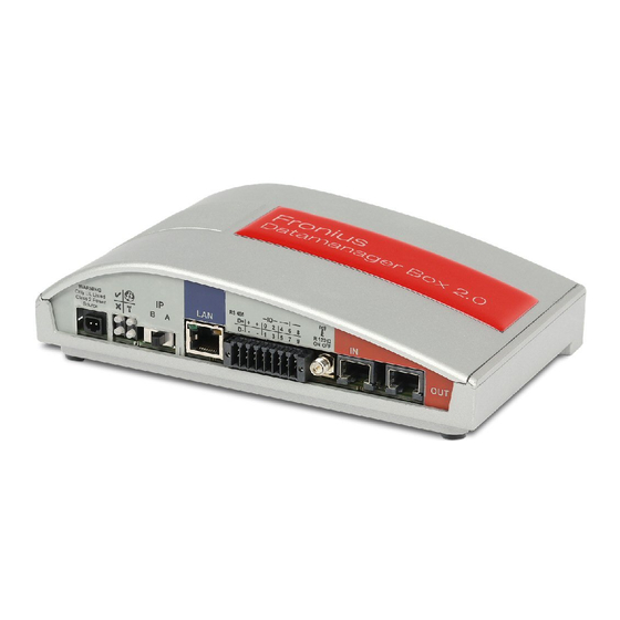
Page 23: Controls, Connections And Indicators
In- dicators (2) (3) (10) (11) Fronius IG Fronius IG Plus Fronius Galvo Fronius IG Plus V Fronius Symo Fronius IG Plus A Fronius Primo Fronius CL Fronius CL USA Fronius IG 300 - 500 (13) (8) (9) (11) (12) - Page 24 (DHCP) The IP address can be set on the Fronius Datamanager 2.0 website. In the case of Fronius Datamanager 2.0 plug-in cards, the IP switch is located underneath the LEDs and is separate in the case of the Fronius Datamanager Box 2.0.
- Page 25 No. Function Connection LED Lights up green: There is an active connection within Fronius Solar Net Lights up red: There is an interrupted connection within Fronius Solar Net Does not light up: Fronius Datamanager 2.0 is in slave mode LAN connection socket...
- Page 26 Fronius Solar Net input colored red for connecting to other DATCOM compo- nents (e.g., inverters, sensor cards) For Fronius Datamanager 2.0 with Fronius Com Card function only! (for Fronius IG, Fronius IG Plus, Fronius IG Plus V, Fronius IG Plus A, Fronius CL, Fronius CL USA, Fronius IG 300–500 inverters)
-
Page 27: Schematic Connection Of I/Os
(for Fronius Datamanager 2.0 with Fronius Com Card function only) Current limit Fronius Solar Net IN connection socket 115–230 V AC: Fronius IG, Fronius IG Plus, Fronius IG Plus V, Fronius IG Plus A, Fronius CL, Fronius CL USA, Fronius IG 300–500 12.8 V DC: Fronius Galvo, Fronius Symo... - Page 28 NOTE! When the supply is via an external power supply, the external power sup- ply must be galvanically isolated. 10.7 V DC: Fronius IG, Fronius IG Plus, Fronius IG Plus V, Fronius IG Plus A, Fronius CL, Fronius CL USA, Fronius IG 300–500 12.8 V DC:...
-
Page 29: Installing Fronius Datamanager 2.0
Installing Fronius Datamanager 2.0... -
Page 31: Inserting Fronius Datamanager 2.0 Into An Inverter
Please note the safety and warning information in your inverter's operating instructions. IMPORTANT! Before inserting the Fronius Datamanager 2.0 plug-in card, remove any ex- isting Fronius Com Card, Fronius Power Control Card, or Fronius Modbus Card! Safety WARNING! An electric shock can be fatal. -
Page 32: Fronius Datamanager 2.0 Plug-In Positions
Fronius Primo does not matter If an ENS plug-in card is inserted in the ENS slot: Insert Fronius Datamanager 2.0 in the next slot to the right of the ENS slot. IMPORTANT! The next slot must be kept free. -
Page 33: Installing And Connecting Wlan Antennas
Connect the antenna cable to the an- tenna socket on the Fronius Datamanager 2.0 plug-in card Run the antenna cable out through the DATCOM opening on the inverter... -
Page 34: Fronius Ig Usa, Fronius Ig Plus Usa, Fronius Ig Plus V Usa: Installing And Connecting Antennas
Run the antenna cable through the drill hole on the mounting bracket Attach the lock washer and screw on 0,9 Nm the hex nut Screw on the antenna Fronius IG USA, Fronius IG Plus USA, Fronius IG Plus V USA: In- stalling and Con- necting Antennas CAUTION! Danger of short circuit caused by loose metal parts from knockouts. - Page 35 19 mm 3/4 in. 0.9 Nm 8 in-lb NOTE! In order to ensure leak-tightness, the sealing ring must be fitted to the an- tenna screw joint before inserting the antenna screw joint into the inverter hous- ing. 8 Nm 5.90 ft. lb. Bending radius of the antenna cable: at least 25.4 mm/1 in.
- Page 36 0.9 Nm 8 in-lb...
-
Page 37: Installing Fronius Datamanager 2.0 In Fronius Solar Net
The Fronius Solar Net cable should only be inserted into the Fronius Solar Net IN connection socket (colored red). Installing Invert- Fronius IG, Fronius IG Plus, Fronius IG Plus V, Fronius IG Plus A, Fronius CL, Fro- ers with Fronius nius CL USA, Fronius IG 300–500: Datamanager 2.0... -
Page 38: Installing Fronius Datamanager Box 2.0 In Fronius Solar Net
Insert the Ethernet cable into the PC/laptop or into a suitable network connection sock- If only one inverter with Fronius Datamanager 2.0 is linked to a PC: Fronius IG, Fronius IG Plus, Fronius IG Plus V, Fronius IG Plus A, Fronius CL, Fronius CL USA, Fronius IG 300 - 500:... - Page 39 Insert the Fronius Solar Net cable into the Fronius Solar Net OUT connection socket of the Fronius Datamanager Box 2.0 Insert the Fronius Solar Net cable into the Fronius Solar Net IN connection socket of the inverter as per the inverter operating instructions...
-
Page 40: Fronius Solar Net Cabling
DATCOM components will hereinafter be referred to as Fronius So- lar Net. Fronius Solar Net The data connection for the Fronius Solar Net client is a 1:1 connection using 8-pin data Client Cabling cables and RJ-45 plugs. -
Page 41: Preassembled Data Cables
ISO/IEC 11801:2002 internationally TIA/EIA 568 for North America Rules for use of copper cables apply. Preassembled The following preassembled data cables are available from Fronius: data cables CAT5 cable 1 m ... 43,0004,2435 CAT5 cable 20 m ... 43,0004,2434 CAT5 cable 60 m ... 43,0004,2436 The cables listed above are 8-pin, 1:1 LAN network cables, shielded and twisted, including RJ 45 plugs. -
Page 42: Installing Fronius Datamanager 2.0 - Overview
Fronius Solar Net IMPORTANT! Inverters Fronius IG, Fronius IG Plus, Fronius IG Plus V, Fronius IG Plus A, Fronius CL, Fronius CL USA, and Fronius IG 300–500 must always be located at the beginning or end of the Fronius Solar Net ring. - Page 43 Switch the device to service mode Inverter with Fronius Datamanager 2.0 plug-in card: Switch the IP switch on the Fronius Datamanager 2.0 plug-in card to position A Activate the WIFI Access Point via the Setup menu of the inverter (the performance of this function depends on the inverter software)
-
Page 44: Starting For The First Time Via Web Browser
To start Fronius Datamanager 2.0 for the first time, the Fronius Datamanager 2.0 plug-in card must be installed in the inverter, there must be a Fronius Datamanager Box 2.0 in the Fronius Solar Net ring. IMPORTANT! To establish a connection to Fronius Datamanager 2.0, the end device in question (e.g., laptop, tablet) must be configured as follows:... - Page 45 Fronius Solar Net IMPORTANT! Inverters Fronius IG, Fronius IG Plus, Fronius IG Plus V, Fronius IG Plus A, Fronius CL, Fronius CL USA, and Fronius IG 300–500 must always be located at the beginning or end of the Fronius Solar Net ring.
- Page 46 The inverter/Fronius Datamanager Box 2.0 establishes the WLAN Access Point. The WLAN Access Point stays open for one hour. Connect the end device to the WLAN Access Point SSID = FRONIUS_240.xxxxx (5–8 digits) Search for a network with the name "FRONIUS_240.xxxxx"...
- Page 47 The Fronius Solar.web start page appears. The Fronius Datamanager 2.0 website opens.
-
Page 49: Establishing A Connection To Fronius Datamanager
Establishing a Connection to Fronius Datamanager 2.0... -
Page 51: Connecting To Fronius Datamanager 2.0 Via A Web Browser
Browser General The connection to Fronius Datamanager 2.0 via a web browser is suitable for accessing current values with several PC users in a LAN (e.g., company networks, schools). For example, total and daily yields can be accessed and/or inverter comparisons can be made on the Fronius Datamanager 2.0 website. -
Page 52: Connecting To Fronius Datamanager 2.0 Via The Internet And Fronius Solar.web
Connecting to Fronius Datamanager 2.0 via the In- ternet and Fronius Solar.web General By connecting to Fronius Datamanager 2.0 via the internet and Fronius Solar.web, you can access archived data and up-to-date photovoltaic system data online from anywhere in the world with internet access. -
Page 53: Current Data, Services, And Settings On Fronius Datamanager
Current Data, Services, and Settings on Fronius Datamanager 2.0... -
Page 55: The Fronius Datamanager 2.0 Website
Fronius Dataman- The following data is displayed on the Fronius Datamanager 2.0 website: ager 2.0 Website – Overview (1) Current comparison view of all inverters in the Fronius Solar Net ring (2) System overview: Current/Day/Year/Total (3) Inverter (4) Sensors (5) Services... -
Page 56: The Settings Menu
Menu items in Settings menu Other Setting Op- Other setting options are shown in the top right corner of the Fronius Datamanager 2.0 tions website: System information: Data logger ID, software version, hardware version, Solar Net connection, Solar.web connection... -
Page 57: Current Data In Fronius Datamanager 2.0
Current Data in Fronius Datamanager 2.0 Current Compari- son View Several inverters in the same photovoltaic system can be compared in the current Com- parison View. The real-time inverter AC power is displayed as a percentage of the power from the solar module connected to the respective inverter (shown in a bar diagram). -
Page 58: System Overview
System Overview The system overview contains: system overview the real-time power data of a photovol- taic system the active devices Actual the energy generated per day, per ye- ar, and in total the yield per day, per year, and in total The values for consumption and energy fed into the grid are only dis- played when a counter is configu-... -
Page 59: Inverter/Sensors View
Inverter/Sensors Inverter View View The Inverter View displays all the inverters present in the system. Clicking on an inverter or the corre- sponding bar in the Comparison View displays the inverter's real- time data: 80 kWh 12 MWh 36 MWh Sensor View The Sensor View displays all the sensor cards/boxes present in the system. -
Page 60: Services - System Information
The network settings and all items protected by the service user (UC Editor, count- er settings, and service password) are retained Option "All settings" Used to reset Fronius Datamanager 2.0 and the network settings to the factory set- tings. All items protected by the service user (UC Editor, counter settings, and service password) are retained IMPORTANT! When Fronius Datamanager 2.0 is reset to factory settings, the time and... -
Page 61: Services - Network Diagnostics
Services – Network Diagnostics Network Diagnos- The Services / Network diagnostics option contains functions that are useful for diagnosing tics and correcting network problems. Ping and traceroute commands can be executed. The ping command is used to determine whether or not a host is available and how much time a data transfer will take. -
Page 62: Services - Firmware Update
Services – Firmware Update General You can update the Fronius Datamanager 2.0 firmware under Services / Firmware Update. A firmware update can be performed via LAN or web. Automatic update search "Check now" button (to search for updates manually) Use proxy server for Web update... -
Page 63: Manual Update Search
When the "Automatic update search" option (1) is activated, Fronius Datamanager 2.0 will automatically search for updates once a day. If new updates are available, a message is displayed under the other setting options of the Fronius Datamanager 2.0 website. -
Page 64: Firmware Update Via Lan
Download the current firmware from the Fronius homepage Run the downloaded update file on the PC/laptop This will start a web server from which Fronius Datamanager 2.0 will download the re- quired files. Open the Fronius Datamanager 2.0 website via a web browser Open "Firmware update"... - Page 65 The update starts. The update progress is displayed as a bar and a percentage. Once the update has been carried out successfully, click on the "Apply/Save" button The update is complete when the "Supply LED" lights up green. If the connection to the server fails: Deactivate the firewall for the duration of the update Retry the update...
-
Page 66: Services - Opening Wizards
Services – Opening Wizards Opening Wizards The Commissioning Wizard can be opened again and run under "Open Wizards."... -
Page 67: Settings - General
The date (3), hour (4), and minutes (5) can be entered under "System time." Click "Synchronize" (6) to adapt the displayed time in the entry fields of the Fronius Datamanager 2.0 website to the time set on the computer operating system. -
Page 68: Settings - Passwords
Administrator password, user name = admin The administrator password set during commissioning assigns the user read and write (configuration) access to Fronius Datamanager 2.0. The user can then open the "Settings" menu item and define any settings as desired, with the exception of the UC Editor and Counter. - Page 69 An assigned user password only gives the user read access to Fronius Dataman- ager 2.0. The user cannot open the "Settings" menu item. When assigning a user password, users must enter their username and password every time they connect to Fronius Datamanager 2.0.
-
Page 70: Settings - Inverter
The data for the Comparison View is defined in "Inverter." Field for assigning a system name * Number of the inverter in Fronius Solar Net If the selection field is chosen, the inverter is displayed in the Comparison View Display of device type... -
Page 71: Settings - Fronius Sensor Cards
Settings – Fronius Sensor Cards Sensor Cards A specific channel name can be assigned to each sensor value of a Fronius Sensor Card/ Box in "Sensor Cards" (e.g., wind speed). Sensor Card selection Displayed measuring channel Fields for assigning the channel name "Apply/Save"... -
Page 72: Settings - Fronius Solar.web
Settings – Fronius Solar.web Solar.web The Solar.web menu item can be used to make a direct connection between Fronius Data- manager 2.0 and Fronius Solar.web. (10) Datalogging settings Selection of query cycle for the inverter: Data queries every 5/10/15/20/30 minutes... - Page 73 (7a) (7a) Fields for selecting the time (hour) "Register Solar.web" link Clicking this link opens the Fronius Solar.web start page; data relevant for Fronius Solar.web is automatically sent as well. "Apply/Save" button (10) "Cancel/Discard entries" button...
-
Page 74: Settings - Service Messages
Settings – Service Messages General Service messages, inverter errors, Fronius String Control, etc., are sent to Fronius Data- manager 2.0 and saved. The "Service messages" selection option is used to define how service messages are communicated. They can be communicated via: E-mail Service messages can be analyzed further using Fronius Solar.web. - Page 75 (11) "Send test SMS" button Sending a test SMS may take several minutes. (12) Selection field for the language in which the service message will be sent (13) "Apply/Save" button (14) "Cancel/Discard entries" button...
-
Page 76: Settings - Network
Settings – Network General The "Network" menu item is used to determine the type of internet connection (LAN or WLAN). IMPORTANT! If the IP address is obtained statically, a gateway and a DNS server must be entered for the selected network interface. Network (21) (22) - Page 77 Obtain IP address statically The user enters a fixed IP address for Fronius Datamanager 2.0 and also manually sets the subnet mask, gateway address, and DNS server address (from the pro- vider). Obtain IP address dynamically Fronius Datamanager 2.0 obtains its IP address from a DHCP server (DHCP = dy- namic host configuration protocol).
- Page 78 Connection (15a) Network: (15b) Security: (15c) Enter password: (15d) Show password: (15e) Save Cancel (15f) (15a) Name of hidden WLAN network (15b) Selection field for encrypting the hidden WLAN network (15c) Field for entering the password for the hidden WLAN network (15d) Selection field for whether the password is displayed (15e)
- Page 79 (19) (20) (19) "OK" button (20) "Cancel" button (21) "Apply/Save" button (22) "Cancel/Discard entries" button...
-
Page 80: Settings - Energy Manager
Settings – Energy Manager General The output I/O 1 can be used to control an actuator (e.g., relay, contactor) via the "Energy Manager" function. A load connected to I/O 1 can thus be controlled by assigning a power feed-dependent switch-on or switch-off point. Energy Manager (14) (15) - Page 81 Field for entering a minimum time for which the output I/O 1 is to be activated for each switch-on process Field for activating the maximum runtime per day Field for entering a maximum time for which the output I/O 1 is to be activated in total per day (several switch-on processes are included).
-
Page 82: Settings - Push Service
Settings – Push Service Push Service This function can be used to export current and log data in different formats or with different protocols to an external server. "Apply/Save" button "Cancel/Discard entries" button "Add" button Clicking this button adds a new push service job. The new job is saved by clicking the "Apply/Save"... -
Page 83: Further Information About The Push Service Function
Password "Delete" button Clicking this button deletes the selected push service job Further Informa- Further information about the push service function can be found in the following operating tion about the instructions: Push Service Function http://www.fronius.com/QR-link/4204102152 42.0410.2152 Fronius Push Service... -
Page 84: Modbus Settings
Modbus Settings General From your web browser, you can use the Fronius Datamanager 2.0 website to apply the Modbus connection settings which cannot be accessed via the Modbus protocol. Additional Infor- For additional information on the Modbus function, please see the following operating in-... - Page 85 Number of the TCP port which must be used for Modbus communication. (2b) Fronius String Control address offset Offset value used to assign addresses to Fronius String Controls via Modbus. For further details, see the section entitled "Modbus Device ID for Fronius String Controls." (2c) Demo mode The demo mode is used to implement or validate a Modbus master.
-
Page 86: Limit Control
Selection field for entering the parity (3c) Fronius String Control address offset Offset value used to assign addresses to Fronius String Controls via Modbus. For further details, see the section entitled "Modbus Device ID for Fronius String Controls." (3d) Demo mode The demo mode is used to implement and validate a Modbus master. -
Page 87: Save Or Reject Changes
IP address To limit inverter control to one or more devices, enter the IP addresses of the de- vices which are permitted to send commands to Fronius Datamanager 2.0 in this field. Multiple entries are separated by commas. Examples: One IP address: 98.7.65.4... -
Page 88: Settings - Counter
The service password must be entered for the "Counter" menu item. Counter Field for selecting a counter: - none selected - Fronius Smart Meter - S0 inverter (for Fronius Galvo, Fronius Symo, and Fronius Primo inverters only) Link to counter circuit diagrams "Apply/Save" button "Cancel/Discard entries" button... -
Page 89: S0 Inverter
(1a) (1b) Connecting the Fronius Smart Meter to Fronius Datamanager 2.0: Fronius Fronius Smart Meter OUTPUT RS 485 Datamanager DT/PE INPUT Rx / Tx GND 9 11 120 Ω LOAD X X X S0 inverter (1c) (1a) (1b) (1a) Counter position at feed-in point The power of feeding in and energy are measured. - Page 90 (1b) A counter for recording self-consumption per S0 can be connected directly to the inverter (Fronius Galvo and Fronius Symo only). IMPORTANT! An S0 counter is connected to the switchable multifunctional current inter- face of the inverter. Connecting an S0 counter to the inverter may require an inverter firm- ware update.
-
Page 91: Settings - Uc Editor
Settings – UC Editor General In the "UC Editor" menu item, settings relevant to a utility company are made. An effective power limit in % and/or a power factor limit can be set. IMPORTANT! Settings in the "UC Editor" menu item may only be made by staff trained to do so! The service password must be entered for the "UC Editor"... -
Page 92: Connection Example
PDF or print them out (e.g., as a commissioning report). Connection Ex- Ripple control signal receiver with 3 relays for effective power limitation ample Ripple control signal receiver with 3 relays for power factor limitation I/Os on Fronius Datamanager 2.0 Loads (e.g., signal light, signal relay) -
Page 93: Uc Editor - Dynamic Power Reduction
The ripple control signal receiver and the Fronius Datamanager 2.0 plug are connected to one another using a 4-pin cable in accordance with the connection diagram. For distances of greater than 10 m between Fronius Datamanager 2.0 and the ripple con- trol signal receiver, a shielded cable is recommended. -
Page 94: Uc Editor - Control Priorities
If no counter has been selected in the "Counter" menu item: Max. power generated for the entire system If Fronius Smart Meter or S0 inverter has been selected in "Counter" menu item: Max. energy fed into the grid Selection field % or W "Apply/Save"... - Page 95 1 = highest priority, 3 = lowest priority Used to set control priorities for the ripple control signal receiver Used to set control priorities for dynamic power reduction Used to set control priorities for control via Modbus "Apply/Save" button "Cancel/Discard entries" button...
-
Page 97: Appendix
Appendix... -
Page 99: Technical Data
Switching capacity of digital outputs when supplied by the Fronius Datamanager 2.0 3.2 W plug-in card 10.8 V Fronius IG, Fronius IG Plus, Fronius IG Plus V, Fronius IG Plus A, Fronius CL, Fronius CL USA, Fronius IG 300–500 12.8 V Fronius Galvo, Fronius Symo... - Page 100 Given sufficient power supply from Fronius Solar Net, the green LED lights up on every DATCOM component. If the green LED does not light up, the power supply unit available from Fronius should be inserted into the 12 V power supply connection socket of an external DATCOM component.
- Page 102 Fronius International GmbH Fronius USA LLC Solar Electronics Division 4600 Wels, Froniusplatz 1, Austria 6797 Fronius Drive, Portage, IN 46368 E-Mail: pv-sales@fronius.com E-Mail: pv-us@fronius.com http://www.fronius.com http://www.fronius-usa.com Under http://www.fronius.com/addresses you will find all addresses of our sales branches and partner firms!
Need help?
Do you have a question about the Datamanager 2.0 and is the answer not in the manual?
Questions and answers