Armstrong 4380 Installation And Operating Instructions Manual
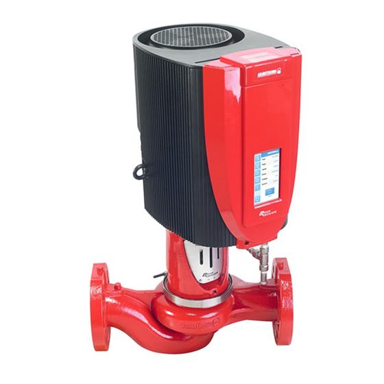
Vertical in-line pumping unit
Hide thumbs
Also See for 4380:
- Service work instructions (3 pages) ,
- Installation and operating instructions manual (66 pages) ,
- Quick installation manual (4 pages)

Related Manuals for Armstrong 4380


Summary of Contents for Armstrong 4380
- Page 1 Design Envelope 4300 & 4380 Vertical In-line Pumping Unit With iECM 1-10 HP Motor Installation and operating instructions File No: 101.80 Date: june 15, 2017 Supersedes: 101.80 Date: may 3, 2017...
-
Page 3: Table Of Contents
contents 1.0 Mechanical setup 3.1 Modbus ip & rtu Precautions 3.2 BACnet ip & ms/ tp 1.1.1 Instructions for safe use 4.0 Operation 1.1.2 Ambient temperature 4.1 Start-up checklist 1.1.3 Enclosure rating 4.2 Starting pump 1.1.4 Storage 4.3 Touch screen 1.1.5 Uncrating 4.3.1 Login 1.1.6 Handling design envelope... -
Page 4: Mechanical Setup
Adequate space, particularly at the fan inlet 2" (50 mm), is necessary to facilitate Armstrong Design Envelope 430 0 & 438 0 Vertical In-Line airflow. Where several Design Envelope units are installed in pumps are thoroughly inspected before shipment to assure close proximity, care must be taken to ensure that there is no they meet with your order requirements. -
Page 5: Mechanical Installation
Design Envelope 4300 & 4380 i n sta l l a t i o n & Vertical In-line Pumping Unit o per at i n g i n str uct i o n s will not free-stand on the casing ribs. Extra care is required to up connection. - Page 6 Armstrong Suction Guide and Flo-Trex valve. with an Armstrong Suction Guide and Flo-Trex valve. Many fig . 1. 2 . 2 . 4 very large vil pumps are installed in this manner.
- Page 7 . 1. 2 . 2 .6 welded flange at the pump should be used to prevent the pos- sibility of pipe mounted pumps rotating in the piping. Armstrong offers grooved suction guides with cast-in outlet flanges and Flo-Trex valves with Armgrip™ fittings to prevent this possibility.
-
Page 8: Pump Piping-General
Design Envelope 4300 & 4380 i n stal l a t io n & Vertical In-line Pumping Unit o p era t ing i nstruct ion s 1. 2 . 2 .10 important: Design Envelope pumps contain a tapped hole in the motor The motor and integrated control assembly has 2 factory bracket above the discharge flange (see fig. -
Page 9: Alignment
The leakage current is of importance to safety during handling/ Armstrong f t v triple function valve may be installed in place operation of the Design Envelope pump if (by mistake) the on- of separate check and isolation valves. -
Page 10: Additional Motor Protection
Design Envelope 4300 & 4380 i nstal latio n & Vertical In-line Pumping Unit operati ng instruction s 2 .1.3 additional motor protection See the below diagram for derating of output current versus altitude at ta = Max. 104°f (40°c) With the exception of supply fuses / MCB’s to protect... -
Page 11: Electrical Specification
Design Envelope 4300 & 4380 insta l l a t io n & Vertical In-line Pumping Unit o per at ing i n str uct io n s 4 Current transducers (Hall Effect-Based Current Sensor). 2 .1. 4 .5 mains supply interference /harmonics A motor integral drive takes up a non-sinusoidal current from mains. -
Page 12: Electrical Installation
Design Envelope 4300 & 4380 i nstal latio n & Vertical In-line Pumping Unit operati ng instruction s 2 .3 electrical installation Analog input Programmable 2 .3 .1 power wiring analog voltage input fig 2 .3 .1 Upper right corner of the motor. Use Access port #1... -
Page 13: The Main Cover Disassembly
Design Envelope 4300 & 4380 in sta ll a t io n & Vertical In-line Pumping Unit o perating in struct io n s 2 .3 .3 the main cover disassembly warning Before removing the system must be disconnected from the mains supply. After switching off, wait for at least 4 minutes for the capacitors to discharge before opening the cover. -
Page 14: Control Terminal Wiring
Design Envelope 4300 & 4380 i n stal l a t io n & Vertical In-line Pumping Unit o p era t ing i nstruct ion s 2 .3 . 4 control terminal wiring 2 .3 .5 digital & analogue input/output fig 2 .3 .3 Motor Control Board... -
Page 15: Supply Fusing
Design Envelope 4300 & 4380 insta l l a t io n & Vertical In-line Pumping Unit o per at ing i n str uct io n s 2 .3 .8 supply fusing 2 . 4 .1 rs 485 wiring... -
Page 16: Networking Controls
Design Envelope 4300 & 4380 i nstal latio n & Vertical In-line Pumping Unit operati ng instruction s 3 .0 networking controls Setup of ba s protocol, Node address, baud rate, and for ip setup 3 .1 modbus ip & rtu... -
Page 17: Bacnet Ip & Ms/ Tp
Design Envelope 4300 & 4380 insta l l a t io n & Vertical In-line Pumping Unit o per at ing i n str uct io n s 3 . 2 BACnet ip & ms/ tp name value r ange... -
Page 18: Operation
Is the area around the pump clean? Check rotation arrow prior to operating the unit. The rotation of all Armstrong 430 0 & 438 0 Vertical Warranty In-Line units is clockwise when viewed from behind Does not cover any damages to the equipment resulting from the motor (nde). -
Page 19: Touch Screen
Design Envelope 4300 & 4380 insta l l a t io n & Vertical In-line Pumping Unit o per at ing i n str uct io n s 4 .3 touch screen 4 .3 .1 login Default Password 1234 1234 4 .3 . -
Page 20: About
Design Envelope 4300 & 4380 i nstal latio n & Vertical In-line Pumping Unit operati ng instruction s 4 .3 .3 about The physical design, software, & user interface are protected by patents & trademarks... -
Page 21: General Settings
Design Envelope 4300 & 4380 insta l l a t io n & Vertical In-line Pumping Unit o per at ing i n str uct io n s 4 .3 . 4 gener al set tings save save... -
Page 22: Manual/Auto Mode
Design Envelope 4300 & 4380 i nstal latio n & Vertical In-line Pumping Unit operati ng instruction s 4 .3 .5 manual /auto mode... -
Page 23: Pump Control
Design Envelope 4300 & 4380 i n sta l l a t i o n & Vertical In-line Pumping Unit o per at i n g i n str uct i o n s 4 .3 .6 pump control Purchased Services... -
Page 24: Alarms & Warnings 2
Design Envelope 4300 & 4380 i nstal latio n & Vertical In-line Pumping Unit operati ng instruction s 4 .3 .7 alarms & warnings... -
Page 25: Trend-Graph
Design Envelope 4300 & 4380 insta l l a t io n & Vertical In-line Pumping Unit o per at ing i n str uct io n s 4 .3 .8 trend - gr aph Head / Time Power / Time 4 . -
Page 26: Constant Pressure
Design Envelope 4300 & 4380 i nstal latio n & Vertical In-line Pumping Unit operati ng instruction s 5 . 2 constant pressure head 1200 Design Envelope pumps can be configured to maintain a 1000 constant pump head in a system as the demand varies. This... -
Page 27: Quadratic Curve Control With Minimum & Maximum Flow Protection
Design Envelope equipment to a installed, ensure water is flowing through the sight flow total quantity of 6 units. indicator and that filter cartridges are replaced as recommend- ed. (See Armstrong files 43 . 85 and 43 . 86 for seal environ- mental instructions). -
Page 28: Lubrication
Design Envelope 4300 & 4380 i nstal latio n & Vertical In-line Pumping Unit operati ng instruction s 6. 2 lubrication 6.3 .1 mechanical seal replacement instructions for rigid split- coupled pumping units (series Pump 430 0 & 4322) Lubrication is not required. There are no bearings in the pump that need external lubrication service. - Page 29 Replace seal gland plate 6.3 . 2 mechanical seal replacement instructions (5 4) and tighten the seal gland plate bolts (5 2,163) evenly for close- coupled pumping units (series 4380 and diagonally to 5 (ft. lbs) for 0.75" seal size. & 4372) When installing the mechanical seal (62), ensure parts are perfectly clean.
- Page 30 Design Envelope 4300 & 4380 i nstal latio n & Vertical In-line Pumping Unit operati ng instruction s with larger motors it is advisable to install a permanent device pry bar may be inserted in between the impeller blades to en-...
-
Page 31: System Cleanliness
Design Envelope 4300 & 4380 insta l l a t io n & Vertical In-line Pumping Unit o per at ing i n str uct io n s cate the stationary seat O-ring or L-cup with a small amount r Lower rotating assembly into place... -
Page 32: Warnings And Alarms
Check the connections between the control card and the vfd. the control card and vfd. Speed The speed set by the vfd is not within Cycle power to the pump. If the alarm re-occurs, contact Armstrong tolerance. Technical Service. Wiring There is an issue in wiring to the vfd Check the wiring to motor. -
Page 33: Warning Messages
Check the settings. Check the input power supply and fuses. Internal Voltage External DC supply maybe overloaded. Check for an overvoltage condition. Internal Internal Drive fault. Write down the code and contact Armstrong technical support. Parameter Incorrect parameter setting. Check the parameter settings. Startup Start up is not possible. -
Page 34: Fuse And Wire Recommendation
Vertical In-line Pumping Unit operati ng instruction s 8.0 fuse and wire recommendation Armstrong recommends ul 2 48 -12 Listed Class rk1 current- limiting and Fast-acting fuses for upstream protection of instal- lations within the nec /ul jurisdiction. Example fuses suitable for upstream protection are detailed below.
Need help?
Do you have a question about the 4380 and is the answer not in the manual?
Questions and answers