Chapters
Table of Contents
Troubleshooting

Related Manuals for Keithley 2600B


Summary of Contents for Keithley 2600B
- Page 1 Series 2600B ® System SourceMeter Instrument Reference Manual 2600BS-901-01 Rev. C / August 2016 *P2600BS-901-01C* 2600BS-901-01 A Greater M easure of Confidence A T ektr onix Company...
- Page 2 © 2012-2016, Keithley Instruments, Inc. Cleveland, Ohio, U.S.A. All rights reserved. Any unauthorized reproduction, photocopy, or use of the information herein, in whole or in part, without the prior written approval of Keithley Instruments, Inc. is strictly prohibited. ® ® ®...
-
Page 3: Safety Precautions
Keithley Instruments products are designed for use with electrical signals that are measurement, control, and data I/O connections, with low transient overvoltages, and must not be directly connected to mains voltage or to voltage sources with high transient overvoltages. - Page 4 (note that selected parts should be purchased only through Keithley Instruments to maintain accuracy and functionality of the product). If you are unsure about the applicability of a replacement component, call a Keithley Instruments office for information.
-
Page 5: Table Of Contents
Rear panel..........................2-6 Cooling vents ........................2-12 Turning your instrument on and off ..................2-13 Procedure..........................2-13 Placing a Series 2600B in standby ..................2-14 Warmup period ........................2-14 Line frequency configuration ....................2-15 Fuse replacement ........................2-15 System information ......................2-15 Menu overview ........................ - Page 6 Table of Contents Series 2600B System SourceMeter® Instrument Reference Manual 4-wire remote sensing connections ..................2-55 Contact check connections ..................... 2-56 Multiple SMU connections ....................... 2-56 Guarding and shielding ......................2-61 Test fixture ..........................2-71 Floating a SMU ........................2-72 DUT connection settings ....................
- Page 7 Guard ............................4-24 Measurement settling time considerations ................. 4-26 For controlling settling time delay .................... 4-27 For analog filter (Models 2634B/2635B/2636B only) ............... 4-27 Effects of load on current source settling time ..............4-27 Creating pulses with the Series 2600B ................4-28...
- Page 8 Table of Contents Series 2600B System SourceMeter® Instrument Reference Manual Pulse rise and fall times ......................4-28 Pulse width ..........................4-29 Introduction to TSP operation ................... 5-1 Introduction to TSP operation ....................5-1 Controlling the instrument by sending individual command messages ........5-1 Queries .............................
- Page 9 Series 2600B System SourceMeter® Instrument Reference Manual Table of Contents Introduction ..........................6-11 What is Lua? ........................... 6-11 Lua basics ..........................6-11 Standard libraries ........................6-25 Programming example ......................6-29 Test Script Builder (TSB) ....................6-29 Installing the TSB software...................... 6-29 Installing the TSB add-in ......................
- Page 10 Table of Contents Series 2600B System SourceMeter® Instrument Reference Manual Example section ........................7-6 Related commands and information ..................7-7 TSP commands ........................7-8 beeper.beep() ..........................7-8 beeper.enable ........................... 7-9 bit.bitand() ..........................7-9 bit.bitor() ..........................7-10 bit.bitxor() ..........................7-10 bit.clear() ..........................7-11 bit.get() ............................
- Page 11 Series 2600B System SourceMeter® Instrument Reference Manual Table of Contents digio.writebit() .......................... 7-64 digio.writeport() ........................7-64 digio.writeprotect ........................7-65 display.clear() .......................... 7-66 display.getannunciators() ......................7-66 display.getcursor() ........................7-68 display.getlastkey() ......................... 7-69 display.gettext() ........................7-70 display.inputvalue() ......................... 7-72 display.loadmenu.add() ......................7-73 display.loadmenu.catalog() .....................
- Page 12 Table of Contents Series 2600B System SourceMeter® Instrument Reference Manual io.close()..........................7-117 io.flush() ..........................7-117 io.input() ..........................7-118 io.open() ..........................7-119 io.output() ..........................7-119 io.read() ..........................7-120 io.type() ..........................7-121 io.write() ..........................7-121 lan.applysettings() ......................... 7-122 lan.autoconnect ........................7-123 lan.config.dns.address[N] ...................... 7-123 lan.config.dns.domain ......................
- Page 13 Series 2600B System SourceMeter® Instrument Reference Manual Table of Contents localnode.revision ......................... 7-157 localnode.serialno ......................... 7-157 localnode.showerrors ......................7-158 makegetter() .......................... 7-159 makesetter() .......................... 7-159 meminfo() ..........................7-160 node[N].execute() ........................7-161 node[N].getglobal() ........................ 7-162 node[N].setglobal() ........................ 7-162 opc() ............................7-163 os.remove() ...........................
- Page 14 Table of Contents Series 2600B System SourceMeter® Instrument Reference Manual smuX.contact.calibratelo() ..................... 7-208 smuX.contact.check() ......................7-209 smuX.contact.r() ........................7-210 smuX.contact.speed ......................7-211 smuX.contact.threshold ......................7-212 smuX.makebuffer() ........................ 7-212 smuX.measure.analogfilter....................7-213 smuX.measure.autorangeY....................7-214 smuX.measure.autozero ....................... 7-215 smuX.measure.calibrateY() ....................7-216 smuX.measure.count ......................7-217 smuX.measure.delay ......................
- Page 15 Series 2600B System SourceMeter® Instrument Reference Manual Table of Contents smuX.trigger.measure.stimulus ..................... 7-261 smuX.trigger.measure.Y() ..................... 7-264 smuX.trigger.MEASURE_COMPLETE_EVENT_ID .............. 7-265 smuX.trigger.PULSE_COMPLETE_EVENT_ID ..............7-265 smuX.trigger.source.action....................7-266 smuX.trigger.source.limitY ....................7-267 smuX.trigger.source.linearY() ....................7-268 smuX.trigger.source.listY() ....................7-269 smuX.trigger.source.logY()....................7-270 smuX.trigger.source.set() ...................... 7-271 smuX.trigger.source.stimulus ....................7-272 smuX.trigger.SOURCE_COMPLETE_EVENT_ID ..............
- Page 16 Table of Contents Series 2600B System SourceMeter® Instrument Reference Manual SweepILogMeasureV() ......................7-359 SweepVLinMeasureI() ......................7-361 SweepVListMeasureI() ......................7-362 SweepVLogMeasureI() ......................7-363 timer.measure.t() ........................7-364 timer.reset() ........................... 7-365 trigger.blender[N].clear() ....................... 7-365 trigger.blender[N].EVENT_ID ....................7-366 trigger.blender[N].orenable....................7-366 trigger.blender[N].overrun ..................... 7-367 trigger.blender[N].reset() ....................... 7-368 trigger.blender[N].stimulus[M] ....................
- Page 17 Series 2600B System SourceMeter® Instrument Reference Manual Table of Contents tspnet.tsp.runscript() ......................7-409 tspnet.write() ......................... 7-410 userstring.add() ........................7-410 userstring.catalog() ....................... 7-411 userstring.delete() ......................... 7-412 userstring.get() ........................7-413 waitcomplete() ........................7-413 Troubleshooting guide ....................8-1 Introduction .......................... 8-1 Error levels ........................... 8-1 Effects of errors on scripts ....................
- Page 18 Table of Contents Series 2600B System SourceMeter® Instrument Reference Manual Next steps ........................10-1 Additional Series 2600B information .................. 10-1 Maintenance ........................A-1 Introduction .......................... A-1 Line fuse replacement ......................A-1 Front panel tests ........................A-2 Keys test ........................... A-3 Display patterns test ........................A-3 Upgrading the firmware ......................
- Page 19 Series 2600B System SourceMeter® Instrument Reference Manual Table of Contents Confirming the active speed and duplex negotiation ............... C-14 Confirming port numbers ......................C-15 Selecting a LAN interface protocol ..................C-15 VXI-11 connection ........................C-15 Raw socket connection ......................C-16 Dead socket connection ......................
- Page 20 Model 2400 emulation ....................G-1 Model 2400 emulation ......................G-1 Loading, running, and configuring Model 2400 emulation ............G-1 Operating the Series 2600B as a Model 2400................G-2 Execute SCPI commands when not in Model 2400 emulation mode ........G-2 Model 2400 compatibility .....................G-3 General compatibility ........................
-
Page 21: Extended Warranty
General information ..............1-4 Welcome ® Thank you for choosing a Keithley Instruments product. The Series 2600B System SourceMeter instrument provides manufacturers of electronic components and semiconductor devices with an instrument that combines source and measurement capabilities in a single instrument called a source-measure unit (also called a SMU). -
Page 22: Customer Documentation
Section 1: Introduction Series 2600B System SourceMeter® Instrument Reference Manual Customer documentation The Series 2600B Quick Start Guide is provided as a hard copy, plus PDF format. Note that the Reference Manual is also provided in PDF format. • Quick Start Guide: Provides unpacking instructions, describes basic connections, and reviews basic operation information. -
Page 23: Capabilities And Features
• USB flash drive access for saving data buffers, test scripts, and user setups • Digital I/O port: Allows the Series 2600B to control other devices (Digital I/O lines not available on the Models 2604B, 2614B, and 2634B) • Web-based characterization tool that provides easy access to data gathering, sweeping, and pulsing features •... -
Page 24: General Information
To display the serial number on the front panel: 1. If the Series 2600B is in remote operation, press the EXIT (LOCAL) key once to place the instrument in local operation. -
Page 25: General Operation
Digits ..................2-86 Speed ..................2-87 Remote communication interfaces ......... 2-88 General ratings The Series 2600B instrument's general ratings and connections are listed in the following table. Category Specification Supply voltage range 100 V AC to 240 V AC, 50 Hz or 60 Hz (autosensing). 240 VA maximum... -
Page 26: Controls, Indicators, And Connectors
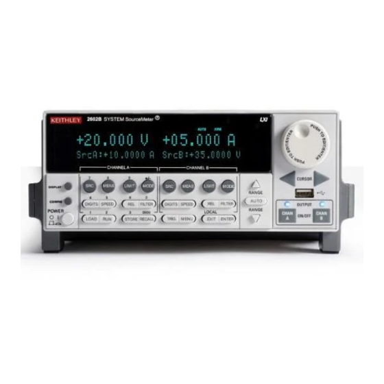
(on page 2-6). Front panel The front panel of the Series 2600B is shown below. The descriptions of the front-panel controls, USB port, and indicators follow the figure. Figure 1: Front panel (Series 2600B models) 2600BS-901-01 Rev. C / August 2016... - Page 27 Section 2: General operation 1. Power switch, display and configuration keys Power switch. The in position turns the Series 2600B on (I); the out position turns it off (O). Toggles between the various source-measure displays and the user message mode.
- Page 28 Section 2: General operation Series 2600B System SourceMeter® Instrument Reference Manual Number keys When enabled and in EDIT mode, the number keys (0-9, +/-, 0000) allow direct numeric entry. Press the navigation wheel to enter EDIT mode. 3. Range keys Selects the next higher source or measure range.
- Page 29 Series 2600B System SourceMeter® Instrument Reference Manual Section 2: General operation 8. Display indicators (not shown) The items listed below represent the possible display indicators and their meanings. Indicator Meaning EDIT Instrument is in editing mode Questionable reading or invalid calibration step...
-
Page 30: Rear Panel
Section 2: General operation Series 2600B System SourceMeter® Instrument Reference Manual Rear panel The rear panel of the Series 2600B is shown below. The descriptions of the rear-panel components follow the figure. Figure 2: Rear panel (Models 2601B, 2602B, 2611B, and 2612B) - Page 31 Series 2600B System SourceMeter® Instrument Reference Manual Section 2: General operation Figure 3: Rear panel (Models 2604B and 2614B) 2600BS-901-01 Rev. C / August 2016...
- Page 32 Section 2: General operation Series 2600B System SourceMeter® Instrument Reference Manual Figure 4: Rear panel (Models 2634B and 2635B) 2600BS-901-01 Rev. C / August 2016...
- Page 33 Series 2600B System SourceMeter® Instrument Reference Manual Section 2: General operation Figure 5: Rear panel (Model 2636B) 2600BS-901-01 Rev. C / August 2016...
- Page 34 Section 2: General operation Series 2600B System SourceMeter® Instrument Reference Manual 1. SMU connector Channel A This connector provides input/output connections for HI and LO, sense (S HI/S LO), and guard (G). Connections are as 2601B/2602B/2604B/2611B/2612B/2614B follows: LO = LO...
- Page 35 Series 2600B System SourceMeter® Instrument Reference Manual Section 2: General operation 3. Digital I/O 2601B/2602B/2611B/2612B/2635B/2636B Female DB-25 connector. Use a cable equipped with a male DB-25 connector (Keithley Instruments part number CA-126-1). Pins provided: Fourteen digital input or output pins, seven GND pins, and three +5 V pins.
-
Page 36: Cooling Vents
Cooling vents The Series 2600B has side and top intake and rear exhaust vents. One side must be unobstructed to dissipate heat. Excessive heat could damage the Series 2600B and degrade its performance. Only operate the Series 2600B in an environment where the ambient temperature does not exceed 50 °C (122 °F). -
Page 37: Turning Your Instrument On And Off
Procedure The Series 2600B operates from a line voltage of 100 V to 240 V at a frequency of 50 Hz or 60 Hz. Line voltage is automatically sensed (there are no switches to set). Make sure the operating voltage in your area is compatible. -
Page 38: Placing A Series 2600B In Standby
= 0 Even though the instrument is placed in standby, the output may not be actually off. Warmup period The Series 2600B must be turned on and allowed to warm up for at least two hours to achieve rated accuracies. 2-14... -
Page 39: Fuse Replacement
Series 2600B System SourceMeter® Instrument Reference Manual Section 2: General operation Line frequency configuration The factory configures the Series 2600B to automatically detect the power line frequency (either 50 Hz or 60 Hz) at each power-up. This detected line frequency is used for aperture (NPLC) calculations. -
Page 40: Menu Overview
Series 2600B System SourceMeter® Instrument Reference Manual Menu overview Menu navigation To navigate through the menus and submenus, the Series 2600B must not be in edit mode (the EDIT indicator is not illuminated). Selecting menu items To navigate the Main and Configuration menus, use the editing keys as follows: •... -
Page 41: Main Menu
Series 2600B System SourceMeter® Instrument Reference Manual Section 2: General operation Main menu The main menu structure is summarized in the following figure and table. For other menu items, see Configuration menus (on page 2-19). Figure 6: Main menu tree 2600BS-901-01 Rev. - Page 42 Section 2: General operation Series 2600B System SourceMeter® Instrument Reference Manual The following table contains descriptions of the main menu options and cross-references to related information. To access a menu option, press the MENU key, turn the navigation wheel to move the cursor to select an item, and press the navigation wheel .
-
Page 43: Configuration Menus
Series 2600B System SourceMeter® Instrument Reference Manual Section 2: General operation Configuration menus The configuration menu structure is summarized in the following figure and table. For directions on navigating the menu, see Menu navigation (on page 2-16). For other menu items, see Main menu page 2-17). - Page 44 Section 2: General operation Series 2600B System SourceMeter® Instrument Reference Manual Figure 8: CONFIG menu tree (models with two SMUs) Press the EXIT key to return to a previous menu. 2-20 2600BS-901-01 Rev. C / August 2016...
-
Page 45: Setting Values
Series 2600B System SourceMeter® Instrument Reference Manual Section 2: General operation The following table contains descriptions of the configuration menus, as well as cross-references to related information. To select a menu for single SMU instruments, press the CONFIG key and then the front-panel key associated with the menu (see the description column in the following table). - Page 46 Setting source and compliance values When the Series 2600B is in the edit mode (EDIT indicator is on), the editing controls are used to set source and compliance values. Note that when you edit the source value, source autoranging is turned off and remains off until you turn it on again.
-
Page 47: Beeper
Section 2: General operation The up and down range keys change the format of the limit value. Beeper The Series 2600B includes a beeper. When it is enabled, a beep indicates one of the following actions have occurred: • A front-panel key was pressed: A short beep, similar to a key click, is issued. -
Page 48: Display Mode
To prevent electrical shock that could cause injury or death, never make or break connections to the Series 2600B while the instrument is powered on. Turn off the equipment from the front panel or disconnect the main power cord from the rear of the Series 2600B before handling cables. -
Page 49: Operation Overview
Series 2600B System SourceMeter® Instrument Reference Manual Section 2: General operation Operation overview Before you begin any of the following front panel procedures, make sure that you exit out of the menu structure. Press the EXIT (LOCAL) key as many times as needed to return to the main display. - Page 50 Section 2: General operation Series 2600B System SourceMeter® Instrument Reference Manual Voltage and current The following table lists the source and measure limits for the voltage and current functions. The full range of operation is explained in Operating boundaries (on page 4-5).
- Page 51 Series 2600B System SourceMeter® Instrument Reference Manual Section 2: General operation Max Power = 40.4 W per channel Max Power = 30.603 W per channel Max Power = 30.603 W per channel 200 V source range available only when 200 V source range available only when interlock is enabled.
- Page 52 Series 2600B can be set to limit voltage or power. In steady-state conditions, the Series 2600B output will not exceed the limit. The maximum limit is the same as the maximum values listed in the following table.
- Page 53 Series 2600B System SourceMeter® Instrument Reference Manual Section 2: General operation Setting the limit Front-panel limit Set the limit from the front panel as follows: 1. For the Model 2601B/2611B/2635B or the Model 2602B/2604B/2612B/2614B/2634B/2636B single-channel display mode, press the LIMIT key to directly access limit editing. Pressing the LIMIT key while in limit edit mode will toggle the display between the complementary function limit and the power limit display.
- Page 54 +10 V, sink operation will occur in the second quadrant (source +V and measure -I). When using the I-Source as a sink, ALWAYS set V-Compliance to a level that is higher than the external voltage level. Failure to do so could result in excessive current flow into the Series 2600B and incorrect measurements. See Limits (on page 2-28) for details about compliance limit.
-
Page 55: Operation Considerations For The Adc
= smua.ENABLE Fundamental circuit configurations The fundamental source-measure configurations for the Series 2600B are shown in the following figure. When sourcing voltage, you can measure current or voltage (see A: Source V). When sourcing current, you can measure voltage or current (see B: Source I). See Basic circuit configurations page 4-20) for detailed information. - Page 56 Series 2600B System SourceMeter® Instrument Reference Manual Autozero The ADC of the Series 2600B uses a ratiometric A/D conversion technique. To ensure accuracy of readings, the instrument must periodically obtain fresh measurements of its internal ground and voltage reference. Separate reference and zero measurements are used for each aperture.
-
Page 57: Basic Source-Measure Procedure
Front-panel source-measure procedure Use the following procedure to perform the basic source-measure operations of the Series 2600B. The following procedure assumes that the Series 2600B is already connected to the device under test (DUT), as explained in DUT test connections (on page 2-49). - Page 58 When not measuring the source (such as when sourcing V but measuring I), measurement range selection can be done manually or automatically. When using manual ranging, use the lowest possible range for best accuracy. When autorange is enabled, the Series 2600B automatically goes to the most sensitive range to make the measurement.
- Page 59 Series 2600B System SourceMeter® Instrument Reference Manual Section 2: General operation Step 5: Observe readings on the display. Press the TRIG key if necessary to trigger the instrument to begin taking readings. The readings are on the top line, and source and limit values are on the bottom line.
- Page 60 Section 2: General operation Series 2600B System SourceMeter® Instrument Reference Manual Requesting readings You can request readings by including the appropriate measurement command as the argument for the print() command. The following programming example illustrates how to request a Channel A current reading: print(smua.measure.i())
-
Page 61: Triggering In Local Mode
Series 2600B System SourceMeter® Instrument Reference Manual Section 2: General operation Triggering in local mode It is not necessary to change any trigger settings to use the basic source and measurement procedures covered in this section. Press the MENU key, and then select SETUP > RECALL > INTERNAL > FACTORY to reset the factory default conditions. -
Page 62: Configuring For Measure-Only Tests Using The Mode Key
2. Turn the navigation wheel to select the type of meter from the menu (I-METER, V-METER, OHM-METER, or WATT-METER). 3. Press the ENTER key to complete the configuration of the Series 2600B as the selected meter. 2-38 2600BS-901-01 Rev. C / August 2016... -
Page 63: V-Meter And I-Meter Measurements
Set compliance to a level that is higher than the expected measurement. When using the Series 2600B as a voltmeter, the voltage compliance limit must be set higher than the voltage that is being measured. Failure to do this could result in excessive current flow into the Series 2600B, incorrect measurements, and possible damage to the instrument. - Page 64 (V/I) to best fit the display. There may be leading zeros if the ohms reading is less than 1 mΩ. Basic ohms measurement procedure When you use the MODE key to select ohms measurement, the Series 2600B is automatically configured as a current source with a level of 1 mA. If you wish to change the source function, source value, or compliance value (in other words, if you wish to customize the MODE key's standard ohm- meter's configuration), then perform the following steps to perform ohms measurements.
- Page 65 Series 2600B System SourceMeter® Instrument Reference Manual Section 2: General operation Ohms programming example The following programming example illustrates the setup and command sequence of a typical ohms measurement procedure with the following parameters: • Source function: current, 10 mA range, 10 mA output •...
- Page 66 Section 2: General operation Series 2600B System SourceMeter® Instrument Reference Manual Figure 12: Two-wire resistance sensing 2-42 2600BS-901-01 Rev. C / August 2016...
-
Page 67: Power Measurements
Basic power measurement procedure If you need to customize the MODE key's standard watt-meter configuration, perform the following steps to perform power measurements. The following procedure assumes that the Series 2600B is already connected to the device under test (DUT) as explained in... - Page 68 Series 2600B while the output is on. Power off the equipment from the front panel or disconnect the main power cord from the rear of the Series 2600B before handling cables connected to the outputs.
-
Page 69: Contact Check Measurements
Series 2600B System SourceMeter® Instrument Reference Manual Section 2: General operation -- Restore Series 2600B defaults. smua.reset() -- Select voltage source function. smua.source.func = smua.OUTPUT_DCVOLTS -- Enable source autoranging. smua.source.autorangev = smua.AUTORANGE_ON -- Set voltage source to 5 V. smua.source.levelv = 5 -- Set current limit to 50 mA. - Page 70 Section 2: General operation Series 2600B System SourceMeter® Instrument Reference Manual Figure 14: Contact check measurements Contact check commands The following table summarizes the basic contact check commands. For a more complete description of these commands, refer to the TSP command reference (on page 7-1).
-
Page 71: Saved Setups
To save a user setup to an external USB flash drive from the front panel: 1. Configure the Series 2600B to the settings that you want to save. 2. Insert the USB flash drive into the USB port on the front panel of the Series 2600B. 3. Press the MENU key. - Page 72 -- Recall the saved user setup from nonvolatile memory. setup.recall(1) Restoring the factory default setups Use one of the reset functions to return the Series 2600B to the original factory defaults. An example of each type of reset is shown in the following program examples. ®...
-
Page 73: Dut Test Connections
(2.5 mm ) conductors. Basic connection sequence: 1. With the output off and the connector uninstalled from the Series 2600B rear panel, make the wire connections from a connector to the DUT. 2. Reinstall the connector onto the rear panel. - Page 74 Measurement Category I only, with transients rated less than 1500 V peak. Do not connect the Series 2600B terminals to CAT II, CAT III, or CAT IV circuits. Connections of the input/output connectors to circuits higher than CAT I can cause damage to the equipment or expose the operator to hazardous voltages.
- Page 75 Series 2600B System SourceMeter® Instrument Reference Manual Section 2: General operation Figure 15: Input/output connectors 2600BS-901-01 Rev. C / August 2016 2-51...
- Page 76 The FVR (in the figure below) is used to isolate the SMUs from high frequencies that may be present on the chassis of the Series 2600B. As frequencies on the chassis increase, the resistance of the FVR increases to dampen its effects.
- Page 77 Series 2600B System SourceMeter® Instrument Reference Manual Section 2: General operation Figure 17: Models 2634B and 2636B input/output and chassis ground terminals (Model 2635B similar) Figure 18: Models 2601B/2602B/2604B/2611B/2612B/2614B low-noise chassis ground banana jack and chassis screw 2600BS-901-01 Rev. C / August 2016...
-
Page 78: Wire Local Sensing Connections
Sourcing and measuring current. • Sourcing and measuring voltage in high impedance (more than 1 kΩ) test circuits. When using 2-wire local sensing connections, make sure to properly configure the Series 2600B Sense mode selection (on page 2-75). Figure 20: Two-wire resistance connections 2-54 2600BS-901-01 Rev. -
Page 79: Wire Remote Sensing Connections
DUT. When measuring voltage, only the voltage drop across the DUT is measured. By default, the Series 2600B instruments are configured to use 2-wire or local voltage sensing. If you choose to enable 4-wire or remote voltage sensing, then it is critical that you establish and maintain the proper Kelvin connections between the corresponding force and sense leads to insure the proper operation of the instrument and to obtain accurate voltage measurements. -
Page 80: Contact Check Connections
Series 2600B instruments. Connections to LO on the Series 2600B are not necessarily at 0 V. Hazardous voltages could exist between LO and chassis ground. Make sure that high-voltage precautions are taken throughout the test system. - Page 81 (on page 6-52) for information on using multiple Series 2600A instruments). A typical application is for the Model 263xB to source a range of gate voltages, while the Series 2600B sources voltage to the drain of the device and measures current at each gate voltage.
- Page 82 Section 2: General operation Series 2600B System SourceMeter® Instrument Reference Manual Figure 23: Two SMUs (Model 2636A) connected to a 3-terminal device (local sensing, floating) 2-58 2600BS-901-01 Rev. C / August 2016...
- Page 83 Series 2600B System SourceMeter® Instrument Reference Manual Section 2: General operation The following figure illustrates using three SMUs to test the same 3-terminal device. The third SMU is connected to the source (S) terminal of the JFET. This allows the source terminal to be biased above signal LO.
- Page 84 Section 2: General operation Series 2600B System SourceMeter® Instrument Reference Manual Figure 25: Model 2636A three SMUs connected to a 3-terminal device (local sensing, non- floating) 2-60 2600BS-901-01 Rev. C / August 2016...
-
Page 85: Guarding And Shielding
A safety shield must be used whenever hazardous voltages (>30 V RMS, 42 V peak) will be present in the test circuit. To prevent electrical shock that could cause injury or death, never use the Series 2600B in a test circuit that may contain hazardous voltages without a properly installed and configured safety shield. - Page 86 Section 2: General operation Series 2600B System SourceMeter® Instrument Reference Manual Safety shielding and hazardous voltages Model 2601B/2602B/2604B: The maximum output voltage for a Model 2601B/2602B/2604B channel is 40 V, which is considered a nonhazardous level. However, using two Model 2601B/2602B/2604B voltage sources in a series configuration or floating a SMU can cause test circuit voltage to exceed 42 V.
- Page 87 Series 2600B System SourceMeter® Instrument Reference Manual Section 2: General operation Model 2611B/2612B/2614B/2634B/2635B/2636B: The maximum output voltage for a Model 2611B/2612B/2614B/2634B/2635B/2636B channel is 220 V, which is considered hazardous and requires a safety shield. The following figures illustrate test connections for these models.
- Page 88 Section 2: General operation Series 2600B System SourceMeter® Instrument Reference Manual Figure 28: Model 2634B/2635B/2636B safety shield for hazardous voltage test circuit connections Guarding A driven guard is always enabled and provides a buffered voltage that is at the same level as the input/output HI voltage.
- Page 89 Series 2600B System SourceMeter® Instrument Reference Manual Section 2: General operation Guard (on page 4-24) for details on the principles of guarding. Figure 29: Models 2602B, 2604B, 2612B,and 2614B high-impedance guarding 2600BS-901-01 Rev. C / August 2016 2-65...
- Page 90 Section 2: General operation Series 2600B System SourceMeter® Instrument Reference Manual Figure 30: Models 2634B and 2636B high-impedance guarding (floating) (Model 2635B is similar) 2-66 2600BS-901-01 Rev. C / August 2016...
- Page 91 Series 2600B System SourceMeter® Instrument Reference Manual Section 2: General operation Figure 31: Model 2634B and 2636B high-impedance guarding (non-floating) (Model 2635B is similar) 2600BS-901-01 Rev. C / August 2016 2-67...
- Page 92 Section 2: General operation Series 2600B System SourceMeter® Instrument Reference Manual Noise shield Use a noise shield (see following figure) to prevent unwanted signals from being introduced into the test circuit. Low-level signals may benefit from effective shielding. The metal noise shield surrounds the test circuit and should be connected to LO, as shown.
- Page 93 Series 2600B System SourceMeter® Instrument Reference Manual Section 2: General operation Figure 33: Models 2634B and 2636B noise shield (floating) (Model 2635B similar) 2600BS-901-01 Rev. C / August 2016 2-69...
- Page 94 Section 2: General operation Series 2600B System SourceMeter® Instrument Reference Manual Figure 34: Models 2634B and 2636B noise shield (non-floating) (Model 2635B similar) Using shielding and guarding together The following figures show connections for a test system that uses a noise shield, a safety shield, and guarding.
-
Page 95: Test Fixture
When properly used, the output of the Series 2600B will turn off when the lid of the test fixture is opened. The test circuit is mounted inside the test fixture. When hazardous voltages (>30 V RMS, 42 V peak) will be present, the test fixture... -
Page 96: Floating A Smu
For the test circuit shown below, the Series 2600B must float off chassis earth ground. As shown, LO of the Series 2600B is floating +10 V above chassis earth ground. If LO of the Series 2600B was instead connected to chassis ground, the external voltage source would be shorted to the chassis ground. - Page 97 Section 2: General operation Figure 36: Floating the Series 2600B schematic The Series 2600B connections for the floating configuration are shown below. In order to float the SMU, input/output LO must be isolated from chassis ground. This is accomplished by not connecting input/output LO to chassis ground.
-
Page 98: Dut Connection Settings
Figure 38: Models 2634B and 2636B SMU connections (Model 2635B similar) The external voltage source can be a SMU of a second Series 2600B instrument or other instrument. Keep in mind that if the combined outputs of the sources exceeds 42 V, then a safety shield will be required for the DUT (see the following WARNINGS). -
Page 99: Sense Mode Selection
To check or change the sense mode from the front panel: 1. Press the CONFIG key. 2. Press the SRC or MEAS key. You can access and set the Series 2600B sense mode from either the V-SOURCE or the V-MEAS menu items. -
Page 100: Output-Off States
Turning a source-measure unit (SMU) off may not completely isolate the SMU from the external circuit. The output-off mode can be used to place the Series 2600B SMU in a known, safe, non-interactive state during idle periods, for example, when changing devices. A Series 2600B SMU can be in one of three output-off modes: Normal, high-impedance, or zero. - Page 101 • Measurements are performed and displayed. The Series 2600B can be used as an I-Meter when it is in zero output-off mode because it will output 0 V, but measure current. To configure the output-off mode from the front panel: 1.
- Page 102 You can set output-off limits (compliance) for the current and voltage output-off functions using the CONFIG menu on the Series 2600B front panel, or by setting the smuX.source.offlimitY attribute from a remote interface. The output-off limits only apply when the output-off mode is normal.
-
Page 103: Usb Storage Overview
Series 2600B System SourceMeter® Instrument Reference Manual Section 2: General operation To set the current limit in NORMAL output-off mode remotely: smuX.source.offlimiti = iValue To set the voltage limit in NORMAL output-off mode remotely: smuX.source.offlimitv = vValue * smuX: For Models 2601B, 2611B, and 2635B, this value is smua (SMU Channel A); for Models 2602B, 2604B, 2612B, 2614B, 2634B, and 2636B, this value can be smua (for SMU Channel A) or smub (for SMU Channel B). -
Page 104: Connecting The Usb Flash Drive
Connecting the USB flash drive The Series 2600B supports flash drives that comply with USB 2.0 standards (as well as USB 1.0 and 1.1 standards). You can save data to the USB flash drive from the front panel, or you can create a script to save data to the USB flash drive. -
Page 105: Displayed Error And Status Messages
To update the displayed reading, trigger a measurement (if in local control, press the TRIG key). Available ranges The following table lists the available source and measurement ranges for the Keithley Instruments ® Series 2600B System SourceMeter instrument. -
Page 106: Manual Ranging
Section 2: General operation Series 2600B System SourceMeter® Instrument Reference Manual Maximum source values and readings The full-scale output for each voltage and current source range is 101 percent of the selected range, but the full-scale measurement is 102 percent of the range. For example, ±1.01 A is the full-scale source value for the 1 A range, and ±102 mA is the full-scale reading for the 100 mA measurement... -
Page 107: Autoranging
Low range limits The low range limit sets the lowest range that the Series 2600B will use when autoranging is enabled. This feature is useful for minimizing autorange settling times when numerous range changes are involved. -
Page 108: Range Considerations
Section 2: General operation Series 2600B System SourceMeter® Instrument Reference Manual Range considerations The source range and measure range settings can interact depending on the source function. Additionally, the output state (on/off) can affect how the range is set. The following table describes these interactions: If... -
Page 109: Range Commands
Series 2600B System SourceMeter® Instrument Reference Manual Section 2: General operation Range programming Range commands The following tables summarize commands necessary to control measure and source ranges. See TSP command reference (on page 7-1) for more details about these commands. -
Page 110: Digits
Section 2: General operation Series 2600B System SourceMeter® Instrument Reference Manual Range programming example The programming example below illustrates how to control both source and measure ranges. The Series 2600B is set up as follows: • Voltage source range: Auto •... -
Page 111: Speed
Series 2600B System SourceMeter® Instrument Reference Manual Section 2: General operation Setting display resolution from a remote interface The following table summarizes use of the display.smuX.digits command. See the command reference (on page 7-1) for more information. Digits commands Command* Description display.smuX.digits = display.DIGITS_4_5... -
Page 112: Remote Communication Interfaces
You can choose from one of several communication interfaces to send commands to and receive responses from the Series 2600B. You can control the Series 2600B from only one communication interface at a time. The first interface on which it receives a message takes control of the instrument. If another interface sends a message, that interface can take control of the instrument. -
Page 113: Supported Remote Interfaces
• RS-232. The Series 2600B can be controlled from only one communication interface at a time. The first interface from which it receives a message takes control of the instrument. It ignores the other interfaces until the instrument is returned to local operation. - Page 114 Section 2: General operation Series 2600B System SourceMeter® Instrument Reference Manual Figure 40: Series 2600B IEEE-488, LAN, USB, and RS-232 connections 1 IEEE-488 connection 2 LAN connection 3 USB connection 4 RS-232 connection 2-90 2600BS-901-01 Rev. C / August 2016...
-
Page 115: Output Queue
This requires that you determine the parameters. You can gather this information by running a utility that automatically detects all instruments connected to the computer. If you installed the Keithley I/O Layer, the Keithley Configuration Panel is available from the ®... - Page 116 Section 2: General operation Series 2600B System SourceMeter® Instrument Reference Manual Figure 41: Select Operation dialog box 3. Click Next. The Select Communication Bus dialog box is displayed. Figure 42: Select Communication Bus dialog box 2-92 2600BS-901-01 Rev. C / August 2016...
- Page 117 Series 2600B System SourceMeter® Instrument Reference Manual Section 2: General operation 4. Select USB. 5. Click Next. The Select Instrument Driver dialog box is displayed. Figure 43: Select Instrument Driver dialog box 6. Select Auto-detect Instrument Driver - Model. 7. Click Next. The Configure USB Instrument dialog box is displayed with the detected instrument VISA resource string displayed.
- Page 118 10. Click Finish. 11. Click Cancel to close the Wizard. 12. Save the configuration. From the Configuration Utility, select File > Save. 13. In the Keithley Communicator, select File > Open Instrument to open the instrument you just named. 2-94...
- Page 119 Series 2600B System SourceMeter® Instrument Reference Manual Section 2: General operation Figure 45: Keithley Communicator Open Instrument 14. Click OK. 15. Send a command to the instrument and see if it responds. If you have a full version of NI VISA on your system, you can run NI-MAX or the VISA Interactive Utility.
-
Page 120: Lan Communications
Series 2600B System SourceMeter® Instrument Reference Manual LAN communications The Series 2600B is an LXI version 1.4 Core 2011 compliant instrument that supports TCP/IP and complies with IEEE Std 802.3 (ethernet). There is one LAN port (located on the rear panel of the instrument) that supports full connectivity on a 10 Mbps or 100 Mbps network. - Page 121 When the LED is: The network: is not connected is connected Blinking is sending or receiving data Using the LAN with remote operations The following table lists the Series 2600B remote interface's available LAN protocols: LAN protocols Port number Protocol Telnet 1024 VXI-11...
-
Page 122: Supplied Software
There are several different styles of instrument drivers. Keithley Instruments provides three different instrument drivers for the Series 2600B: A native LabVIEW driver, an IVI-C driver, and an IVI-COM driver. You need to pick the style that best suits the application development environment (ADE) that you are using. - Page 123 Series 2600B System SourceMeter® Instrument Reference Manual Section 2: General operation VXIPnP drivers VXI (Vixie) plug-and-play (VXIPnP) style drivers are Win32 DLLs that have some standard functions defined by the VXIPnP Alliance, such as: • init • close • error_message •...
- Page 124 Section 2: General operation Series 2600B System SourceMeter® Instrument Reference Manual Instrument driver examples All Keithley drivers come with examples written in several programming languages that show you how to do the most common things with the instruments. ® ®...
-
Page 125: Keithley I/O Layer
Section 2: General operation Keithley I/O layer The Keithley I/O Layer (KIOL) is a software package that contains several utilities and drivers. It is mainly used as a supplement to IVI drivers, or application software like Test Script Builder (TSB). -
Page 126: Gpib Operation
Before installing, it is a good idea to check the Keithley Instruments webite (http://www.tek.com/keithley) to see if a later version of the Keithley I/O Layer is available. On the website, select the Support tab, under model number, type KIOL, and select Software Driver. - Page 127 Series 2600B System SourceMeter® Instrument Reference Manual Section 2: General operation GPIB standards The GPIB is the IEEE-488 instrumentation data bus, which uses hardware and programming standards originally adopted by the Institute of Electrical and Electronic Engineers (IEEE) in 1975.
-
Page 128: Primary Address
Series 2600B System SourceMeter® Instrument Reference Manual Primary address The Series 2600B ships from the factory with a GPIB primary address of 26. If the GPIB interface is enabled, it momentarily displays the primary address on power-up. You can set the address to a value from 0 to 30, but do not assign the same address to another device or to a controller that is on the same GPIB bus (controller addresses are usually 0 or 21). -
Page 129: General Bus Commands
SPE, SPD (on page 2-106) for details. The remote enable (REN) command is sent to the Series 2600B by the controller to set up the instrument for remote operation. Generally, the instrument should be placed in the remote mode before you attempt to program it over the bus. Setting REN true does not place the instrument in the remote state. -
Page 130: Error And Status Messages
The group execute trigger (GET) command is a GPIB trigger that triggers the instrument to take readings from a remote interface. SPE, SPD Use the serial polling sequence to obtain the Series 2600B serial poll byte. The serial poll byte contains important information about internal functions (see Status model (on page 5-15, on page E- 1)). - Page 131 Series 2600B System SourceMeter® Instrument Reference Manual Section 2: General operation Communication status indicators The remote (REM), talk (TALK), listen (LSTN), and service request (SRQ) indicators show the communication bus status. Each of these indicators is described below. Status indicator...
-
Page 132: Local Key
This topic contains information about configuring RS-232 communication parameters, sending or receiving command messages, and requesting or retrieving data. To control the Series 2600B, connect a controller or personal computer to the Series 2600B RS-232 interface. Alternatively, you can use the Series 2600B to control another device over RS-232. -
Page 133: Sending And Receiving Data
1200 The factory-selected baud rate is 9600. Both the Series 2600B and the other device must be configured for the same baud rate. Make sure the device connected to the Series 2600B RS-232 port can support the selected baud rate. - Page 134 Series 2600B System SourceMeter® Instrument Reference Manual RS-232 connections Connect the RS-232 serial port of the Series 2600B to the serial port of a computer using a straight- through RS-232 cable terminated with DB-9 connectors. Do not use a null modem cable. The serial port uses the transmit (TXD), receive (RXD), CTS and RTS (if flow control is enabled), and signal ground (GND) lines of the RS-232 standard.
-
Page 135: Functions And Features
For example, if 0.5 A is set as a relative offset value on the 1 A range, the relative offset value is also 0.5 A on the lower current ranges. Also, on the 1 A range, the Series 2600B still overflows for a more than 1.02 A input. -
Page 136: Relative Offset
Section 3: Functions and features Series 2600B System SourceMeter® Instrument Reference Manual To establish a unique relative offset value from the front panel: 1. Press the CONFIG key and then the REL key. 2. Select the measurement function (CURRENT, VOLTAGE, OHMS, or WATTS), and then press ENTER or the navigation wheel . -
Page 137: Filters
(from 1 to 100). Filter types The Series 2600B has three filter types. These three filter types are broken down into two averaging filters and one median filter. The two averaging filters are repeating and moving (see figure below). For the repeating filter (which is the power-on default), the stack (filter count) is filled, and the conversions are averaged to yield a reading. -
Page 138: Response Time
Section 3: Functions and features Series 2600B System SourceMeter® Instrument Reference Manual The moving average filter uses a first-in, first-out stack. When the stack (filter count) becomes full, the measurement conversions are averaged, yielding a reading. For each subsequent conversion placed into the stack, the oldest conversion is discarded. -
Page 139: Remote Filter Programming
Series 2600B System SourceMeter® Instrument Reference Manual Section 3: Functions and features To configure the filter: 1. Press the CONFIG key and then the FILTER key. 2. Select TYPE, and then select the filter type: AVERAGE or MEDIAN. • AVERAGE: Use this menu item to select an averaging filter, then select the averaging filter type: MOVING or REPEAT. -
Page 140: Reading Buffers
Reading buffers capture measurements, ranges, instrument status, and output state of the Keithley Instruments Series 2600B. The Series 2600B has two default reading buffers called defbuffer1 and defbuffer2. In addition to the default buffers, you can create user-defined reading buffers. You can use the reading buffers to acquire readings. - Page 141 Series 2600B System SourceMeter® Instrument Reference Manual Section 3: Functions and features Reading buffer options The following listing outlines the menu structure and menu items associated with front panel reading buffer control. This section provides a description for each reading buffer option. Use the procedure in Configuring reading buffers (on page 3-8) as a guideline to configure these reading buffer options.
- Page 142 Section 3: Functions and features Series 2600B System SourceMeter® Instrument Reference Manual Configuring reading buffers To configure reading buffers from the front panel: Enabling or disabling the source value or the timestamp is optional. 1. Press the CONFIG key. 2. Press the STORE key and then choose one of the following: •...
- Page 143 Series 2600B System SourceMeter® Instrument Reference Manual Section 3: Functions and features To configure the instrument to append or overwrite measurements the next time data is acquired: 1. Press the CONFIG key. 2. Press the STORE key and then select STORAGE-MODE. The Storage Mode menu is shown.
- Page 144 Section 3: Functions and features Series 2600B System SourceMeter® Instrument Reference Manual To save the reading buffer data: 1. From the front panel, press the STORE key, and then select SAVE. 2. Select INTERNAL to save to internal nonvolatile memory.
-
Page 145: Remote Reading Buffer Programming
Series 2600B System SourceMeter® Instrument Reference Manual Section 3: Functions and features Timestamp If the timestamp is enabled, the first source-measure reading stored in the buffer (#0000001) is timestamped at 0.000 seconds. Subsequent readings are timestamped relative to when the first measurement was made. - Page 146 Section 3: Functions and features Series 2600B System SourceMeter® Instrument Reference Manual Reading buffer commands The following table summarizes commands associated with the reading buffers. See the command reference (on page 7-1) for detailed reading buffer command information. Reading buffer commands*...
- Page 147 Series 2600B System SourceMeter® Instrument Reference Manual Section 3: Functions and features Buffer storage control attributes The following table contains buffer storage control attributes. Before changing the collectsourcevalues, collecttimestamps, or timestampresolution attributes, you must clear the buffer using the smuX.nvbuffer1.clear() or smuX.nvbuffer2.clear() command.
- Page 148 Section 3: Functions and features Series 2600B System SourceMeter® Instrument Reference Manual Buffer read-only attributes The following table contains buffer read-only attributes. Buffer read-only attributes: Read-only attributes used to access buffer parameters Storage attribute Description basetimestamp The timestamp of when the reading at rb[1] was stored, in seconds from midnight January 1, 1970 GMT.
- Page 149 Series 2600B System SourceMeter® Instrument Reference Manual Section 3: Functions and features Statistic attributes Use the smuX.buffer.getstats() function to access the reading buffer data statistics. The table below displays the attributes that you can use to access the reading buffer statistics.
- Page 150 Section 3: Functions and features Series 2600B System SourceMeter® Instrument Reference Manual Reading buffer attributes Use the reading buffer attributes to access the reading buffer data. The table below displays the attributes that you can use to access the reading buffer data.
- Page 151 Series 2600B System SourceMeter® Instrument Reference Manual Section 3: Functions and features Buffer status The buffer reading status attribute includes the status information as a numeric value; see the following table for values. For example, to access status information for the second element of SMU channel A buffer 1, use the following command: stat_info = smua.nvbuffer1.statuses[2]...
- Page 152 The following programming example illustrates how to store data using dedicated reading buffer 1 for channel A. In the example, the Series 2600B loops for voltages from 0.01 V to 1 V with 0.01 V steps (essentially performing a staircase sweep), stores 100 current readings and source values in buffer 1, and then recalls all 100 readings and source values.
- Page 153 The programming example below shows a script for storing both current and voltage readings using buffer 1 for current and buffer 2 for voltage readings. The Series 2600B stores 100 current and voltage readings and then recalls all 100 sets of readings.
-
Page 154: Sweep Operation
Series 2600B System SourceMeter® Instrument Reference Manual Dynamically allocated buffer example The programming example below illustrates how to store data to an allocated buffer called mybuffer. The Series 2600B stores 100 current readings in mybuffer and then recalls all the readings. -- Restore Series 2600B defaults. - Page 155 DC and pulsed list sweeps (C): The list sweep allows you to program arbitrary sweep steps anywhere within the output voltage or current range of the Series 2600B. This portion of the figure (C) shows a list sweep with arbitrary steps and a pulsed list sweep. Pulsed list sweeps function the same way that DC list sweeps function, except that pulsed list sweeps return to the idle level between pulses.
-
Page 156: Sweep Characteristics
Section 3: Functions and features Series 2600B System SourceMeter® Instrument Reference Manual Sweep characteristics For any of the sweep types, program a pulse mode sweep by configuring the end pulse action. Refer Pulse mode sweeps (on page 3-27) for more information. - Page 157 Series 2600B System SourceMeter® Instrument Reference Manual Section 3: Functions and features The sweep can be either positive-going or negative-going, depending on the relative values of the start and stop parameters. When the sweep starts, the output will go to the start source level. The output will then change in equal steps until the stop level is reached.
- Page 158 Section 3: Functions and features Series 2600B System SourceMeter® Instrument Reference Manual The asymptote is used to change the inflection of the sweep curve and allow it to sweep through zero. Both of the following figures depict the effect of the asymptote on the inflection of the sweep curve.
- Page 159 Series 2600B System SourceMeter® Instrument Reference Manual Section 3: Functions and features Solving for k and b provides the following formulas: Where: = The source value at the end point = The source value at the start point start = The number of points in the sweep = The asymptote value The number of points in a sweep is one greater than the number of steps in the sweep.
- Page 160 Section 3: Functions and features Series 2600B System SourceMeter® Instrument Reference Manual In this example: A = 0, V = 1, V = 10, N = 5 start Using the formula above, k = 1 Step size (b) for the sweep in the above figure is calculated as follows:...
- Page 161 Series 2600B System SourceMeter® Instrument Reference Manual Section 3: Functions and features Example: -- Configure a sweep from 1 to 10 V in 10 steps with an asymptote of 0 V. smua.trigger.source.logv(1, 10, 11, 0) -- Enable the source action.
- Page 162 Section 3: Functions and features Series 2600B System SourceMeter® Instrument Reference Manual Timers must be used to configure the pulse width and period. Refer to Using timers to perform pulse mode sweeps (on page 3-45) for details. The pulse width is managed by controlling the duration between the source stimulus event and the end pulse stimulus event.
-
Page 163: Configuring And Running Sweeps
Pulse sweeps can be performed outside of the standard operating area by setting the appropriate compliance level. Review the specifications for the Series 2600B to determine the maximum current and voltage values available in pulse mode. When pulsing in the extended operating area (EOA), the source-measure unit (SMU) will force the pulse to end early if the pulse width exceeds the maximum value. -
Page 164: Sweeping Using Factory Scripts
Section 3: Functions and features Series 2600B System SourceMeter® Instrument Reference Manual Source and measurement delays Whenever the source-measure unit (SMU) outputs a source value in a sweep, it also applies the programmed source delay. The default source delay is zero (0) seconds. Set an additional source delay using the smuX.source.delay attribute. -
Page 165: Sweep Programming Examples
Series 2600B System SourceMeter® Instrument Reference Manual Section 3: Functions and features Sweep programming examples Procedures for programming and running a sweep for three sweep types are given on the following pages. Each of these procedures includes commands for a typical sweep example. The following table summarizes parameters for each of these examples. -
Page 166: Triggering
Section 3: Functions and features Series 2600B System SourceMeter® Instrument Reference Manual Pulse current sweep example The programming example below illustrates a pulse sweep. -- Restore Series 2600B defaults. 1. Configure source functions. Restores defaults and set the compliance to smua.reset() - Page 167 External triggers are possible using digital I/O, TSP-Link synchronization lines, LAN, command interface, and the manual trigger (the TRIG key). The following figure graphically represents all the trigger objects of the Series 2600B instrument. Figure 60: Triggering overview 2600BS-901-01 Rev. C / August 2016...
-
Page 168: Using The Remote Trigger Model
2612B, 2614B, 2634B, and 2636B, this value can be smua (for SMU Channel A) or smub (for SMU Channel B). Using the remote trigger model The source-measure unit (SMU) in the Series 2600B has a remote trigger model that supports a wide range of triggering features for source sweeps, triggered measurements, and pulse actions. - Page 169 Series 2600B System SourceMeter® Instrument Reference Manual Section 3: Functions and features Figure 61: Remote trigger model: Normal (synchronous) mode 2600BS-901-01 Rev. C / August 2016 3-35...
- Page 170 Section 3: Functions and features Series 2600B System SourceMeter® Instrument Reference Manual Figure 62: Remote trigger model: Asynchronous mode 3-36 2600BS-901-01 Rev. C / August 2016...
- Page 171 Series 2600B System SourceMeter® Instrument Reference Manual Section 3: Functions and features When the smuX.trigger.measure.action attribute is set to smuX.DISABLE or smuX.ENABLE, the trigger model will operate in synchronous measurement mode. When it is set to smuX.ASYNC, it will operate in asynchronous mode.
- Page 172 Section 3: Functions and features Series 2600B System SourceMeter® Instrument Reference Manual The source-measure unit (SMU) can be configured to perform any or all available measurements during a sweep using the smuX.trigger.measure.Y() function. To enable the measure action for a simple synchronous sweep, set the smuX.trigger.measure.action attribute to smuX.ENABLE.
-
Page 173: Smu Event Detectors
Series 2600B System SourceMeter® Instrument Reference Manual Section 3: Functions and features SMU event detectors As shown in the Using the remote trigger model (on page 3-34) topic, the source-measure unit (SMU) has multiple event detectors (see the table below) in order to control the timing of various actions. -
Page 174: Using Trigger Events To Start Actions On Trigger Objects
Section 3: Functions and features Series 2600B System SourceMeter® Instrument Reference Manual The programming example below illustrates how to configure a 10-point linear voltage sweep on SMU A, where each step is triggered by the front-panel TRIG key: -- Configure a 10-point source voltage sweep. -
Page 175: Digital I/O Port And Tsp-Link Synchronization Lines
Digital I/O port and TSP-Link synchronization lines The Series 2600B has two sets of hardware lines that can be used for triggering: 14 digital I/O lines ® and three TSP-Link synchronization lines. - Page 176 Specifies the pulse width of the output trigger signal when the hardware line is asserted. Trigger configuration on hardware lines The Series 2600B can be configured to send digital signals to trigger external instruments. Linking these output triggers to the completion of certain source-measure actions enables hardware handshaking.
-
Page 177: Timers
A timer is a trigger object that performs a delay when triggered. Timers can be used to create delays and to start measurements and step the source value at timed intervals. When a delay expires the timer generates a trigger event. The Series 2600B has eight independent timers. Timer attributes Each timer has attributes that you can configure. - Page 178 Section 3: Functions and features Series 2600B System SourceMeter® Instrument Reference Manual Timer delays Timers can be configured to perform the same delay each time or configured with a delay list that allows the timer to sequence through an array of delay values. All delay values are specified in seconds.
- Page 179 Series 2600B System SourceMeter® Instrument Reference Manual Section 3: Functions and features Figure 66: Using a timer for an SDM cycle Timer action overruns The timer generates an action overrun when it generates a trigger event while a timer delay is still in progress.
- Page 180 Section 3: Functions and features Series 2600B System SourceMeter® Instrument Reference Manual The following figure shows the trigger setup for this example. Figure 67: Single pulse triggering Single pulse example code -- Generate a single 500 us, 5 V pulse.
- Page 181 Series 2600B System SourceMeter® Instrument Reference Manual Section 3: Functions and features Pulse train example: The programming example below illustrates how to use two timers: One to control the pulse period, a second to control the pulse width. The example configures the timers and SMU as follows: Timer 1: Pulse period timer •...
- Page 182 Section 3: Functions and features Series 2600B System SourceMeter® Instrument Reference Manual The following figure shows the trigger setup for this example. Figure 69: Pulse train triggering 3-48 2600BS-901-01 Rev. C / August 2016...
-
Page 183: Event Blenders
The ability to combine trigger events is called event blending. You can use an event blender to wait for up to four input trigger events to occur before responding with an output event. The Series 2600B has 1 to 6 event blenders that you can program. 2600BS-901-01 Rev. C / August 2016... -
Page 184: Lan Triggering Overview
Generates an overrun when two events are detected simultaneously. LAN triggering overview Triggers can be sent and received over the LAN interface. The Series 2600B supports LAN extensions for instrumentation (LXI) and has eight LAN triggers that generate and respond to LXI trigger packets. - Page 185 The stateless event flag is a bit in the LXI trigger packet that indicates if the hardware value should be ignored. If it is set, the Series 2600B ignores the hardware value of the packet and generates a trigger event. The Series 2600B always sets the stateless flag for outgoing LXI trigger packets. If the stateless event flag is not set, the hardware value indicates the state of the signal.
-
Page 186: Command Interface Triggering
Make sure to use the same LXI domain on both the Series 2600B instrument and the other instrument. If the Series 2600B has a different LXI domain than the instrument at the other end of the trigger connection, the LXI trigger packets will be ignored by both instruments. -
Page 187: Trigger Generator
Trigger generator The Series 2600B has two trigger generators that can be used to generate trigger events. Use the trigger.generator[N].assert()function to directly trigger events from the command interface or a script (for example, you can trigger a sweep while the instrument is under script control). - Page 188 Series 2600B System SourceMeter® Instrument Reference Manual Detecting trigger events using the wait() function All of the Series 2600B trigger objects (except for SMUs) have built-in event detectors that monitor for trigger events. The event detector only monitors events generated by that object and cannot be configured to monitor events generated by any other trigger object.
- Page 189 Series 2600B System SourceMeter® Instrument Reference Manual Section 3: Functions and features Using the release function of the hardware lines Use the release function to allow the hardware line to output another external trigger when the pulse width is set to 0.
- Page 190 The programming example below illustrates how to configure digital I/O line 2 as an input trigger and digital I/O line 14 as an output trigger. It commands the Series 2600B to wait for an external input trigger on digital I/O line 2. If a trigger event occurs, the Series 2600B outputs an external trigger on digital I/O line 14.
-
Page 191: Hardware Trigger Modes
Hardware trigger modes Different hardware trigger modes can be used for digital I/O and TSP-Link synchronization. Use hardware triggers to integrate Keithley instruments and non-Keithley instruments in a test system. ® The Series 2600B supports 14 digital I/O lines and three TSP-Link synchronization lines that can be used for input or output triggering. - Page 192 Use the rising edge master (RisingM) trigger mode (see the figure titled "RisingM output trigger") to synchronize with non-Keithley instruments that require a high pulse. Input trigger detection is not available in this trigger mode. You can use the RisingM trigger mode to generate rising edge pulses.
- Page 193 Series 2600B System SourceMeter® Instrument Reference Manual Section 3: Functions and features Output characteristics: • Configured trigger events, as well as the digio.trigger[N].assert() and tsplink.trigger[N].assert() commands, cause the physical line state to float high during the trigger pulse duration. •...
- Page 194 Section 3: Functions and features Series 2600B System SourceMeter® Instrument Reference Manual Output characteristics: • In addition to trigger events from other trigger objects, the digio.trigger[N].assert() and tsplink.trigger[N].assert() commands generate a low pulse that is similar to the falling edge trigger mode.
-
Page 195: Understanding Synchronous Triggering Modes
In this mode, the output trigger consists of a low pulse. All non-Keithley instruments attached to the synchronization line in a trigger mode equivalent to SynchronousA must latch the line low during the pulse duration. - Page 196 Section 3: Functions and features Series 2600B System SourceMeter® Instrument Reference Manual Input characteristics: • All rising edges are input triggers. • When all external drives release the physical line, the rising edge is detected as an input trigger. •...
- Page 197 Figure 80: Synchronous acceptor output trigger Synchronous trigger mode The synchronous trigger mode is a combination of SynchronousA and SynchronousM trigger modes. Use the Synchronous trigger mode for compatibility with older Keithley Instruments products. Keithley Instruments recommends using SynchronousA and SynchronousM modes only. Input characteristics: •...
- Page 198 Section 3: Functions and features Series 2600B System SourceMeter® Instrument Reference Manual Figure 81: Synchronous input trigger Output characteristics: • In addition to trigger events from other trigger objects, the digio.trigger[N].assert() and tsplink.trigger[N].assert() functions generate a low pulse for the programmed pulse duration if the line is latched low, a falling edge does not occur.
-
Page 199: High-Capacitance Mode
In normal operation, the SMU in the Series 2600B can drive capacitive loads as large as 10 nF. In high-capacitance mode, the SMU can drive a maximum of 50 µF of capacitance. - Page 200 Series 2600B System SourceMeter® Instrument Reference Manual Understanding source settling times Each Series 2600B source-measure unit (SMU) can drive up to 50 µF of a capacitance in high-capacitance mode. In order to accomplish this, the speed of the Series 2600B SMU is reduced.
-
Page 201: Enabling High-Capacitance Mode
Series 2600B System SourceMeter® Instrument Reference Manual Section 3: Functions and features Adjusting the voltage source When driving large capacitive loads with high-capacitance mode enabled, the response time may be lengthened by the current limit. For example, see the table titled "Current measure and source settling times"... - Page 202 (for SMU Channel B). Measuring current The following inputs are required to test leakage using the factory leakage script, as shown in the script example below. SMU: Sets the Series 2600B source-measure unit to use • levelv: Sets the output voltage level •...
- Page 203 Series 2600B System SourceMeter® Instrument Reference Manual Section 3: Functions and features 2. To run the i_leakage_measure() function in the KIHighC factory script, send: -- Charges the capacitor. smua.source.levelv = 5 smua.source.output = smua.OUTPUT_ON delay(1) imeas = i_leakage_measure(smua, 0, 1, 300e-3, 10e-6, 100e-3)
-
Page 204: Display Features
Section 3: Functions and features Series 2600B System SourceMeter® Instrument Reference Manual Display operations Display functions and attributes The display functions and attributes are used to perform the display operations covered in this section. The following table lists each display function/attribute (in alphabetical order) and cross references it to the section topic where the function/attribute is explained. -
Page 205: Measurement Functions
Series 2600B System SourceMeter® Instrument Reference Manual Section 3: Functions and features Display screen ® Keithley Instruments Series 2600B System SourceMeter instrument displays source-measure values and readings or user defined messages. The display screen options include the following: • Source-measure, compliance screens: Display SMU source-measure readings and compliance values. - Page 206 Section 3: Functions and features Series 2600B System SourceMeter® Instrument Reference Manual For example, while a test is running, the following message can be displayed on the Series 2600B: Test in Process Do Not Disturb The top line of the display can accommodate up to 20 characters (including spaces). The bottom line can display up to 32 characters (including spaces) at a time.
- Page 207 Series 2600B System SourceMeter® Instrument Reference Manual Section 3: Functions and features The function to set cursor position can be used two ways: display.setcursor(row, column) display.setcursor(row, column, style) Where: 1 or 2 column 1 to 20 (row 1) 1 to 32 (row 2)
-
Page 208: Display Character Codes
Section 3: Functions and features Series 2600B System SourceMeter® Instrument Reference Manual Character codes The following special codes can be embedded in the text string to configure and customize the message: $N Starts text on the next line (newline). If the cursor is already on line 2, text will be ignored after the ‘$N’... -
Page 209: Input Prompting
Series 2600B System SourceMeter® Instrument Reference Manual Section 3: Functions and features Returning a text message The display.gettext() function returns the displayed message (text) and can be used in five ways: text = display.gettext() text = display.gettext(embellished) text = display.gettext(embellished, row) text = display.gettext(embellished, row, columnStart) - Page 210 Section 3: Functions and features Series 2600B System SourceMeter® Instrument Reference Manual The following programming example illustrates how to present the operator with the choice of two menu items: Test1 or Test2. If Test1 is selected, the message Running Test1 is displayed. If Test2 is selected, the message Running Test2 is displayed.
-
Page 211: Indicators
Series 2600B System SourceMeter® Instrument Reference Manual Section 3: Functions and features Both the display.inputvalue() and display.prompt() functions display the editable input field, but the display.inputvalue() function does not include the text strings for units and help. After one of the above functions is executed, command execution will pause and wait for the operator in input the source level. -
Page 212: Local Lockout
Binary value * The weighted values are for bits that are set to “1.” Bits set to “0” have no value. Not all of the above indicators shown in above table may be used by the Series 2600B. Local lockout You can use the front-panel EXIT (LOCAL) key to cancel remote operation and return control to the front panel. - Page 213 Functions and variables need to be saved with the script (see Manage scripts (on page 6-3)). If the script is not saved in nonvolatile memory, it is lost when the Series 2600B is turned off. See Example 1 below. Example 1: Assume a script with a function named “DUT1”...
-
Page 214: Running A Test From The Front Panel
Capturing key-press codes A history of the key code for the last pressed front panel key is maintained by the Series 2600B. When the instrument is turned on (or when transitioning from local to remote operation), the key code is set to 0 (display.KEY_NONE). - Page 215 Series 2600B System SourceMeter® Instrument Reference Manual Section 3: Functions and features display.getlastkey() The display.getlastkey() function is used to immediately return the key code for the last pressed key. The following programming example illustrates how to display the last key pressed: key = display.getlastkey()
-
Page 216: Digital I/O
The digital I/O port, a standard female DB-25 connector (shown below), is located on the rear panel. Figure 85: Digital I_O port For a schematic diagram of the digital I/O hardware, refer to the Series 2600B Specifications on the Keithley Instruments webite (http://www.tek.com/keithley). - Page 217 Interlock (on page 3-88) for more details. Use interlock cable assembly CA-558 to connect the Series 2600B interlock to either a Model 8010 High Power Device Test Fixture or to the Model 2657A-LIM-3 LO Interconnect Module (refer to the connection information supplied with the device).
- Page 218 Section 3: Functions and features Series 2600B System SourceMeter® Instrument Reference Manual Digital I/O configuration The following figure shows the basic configuration of the digital I/O port. Writing a 1 to a line sets that line high (~ +5 V). Writing a 0 to a line sets that line low (~0 V). Note that an external device pulls an I/O line low by shorting it to ground, so that a device must be able to sink at least 960 µA per I/O line.
- Page 219 I/O port and individual lines. Use these commands to trigger the Series 2600B using external trigger pulses applied to the digital I/O port, or to provide trigger pulses to external devices.
-
Page 220: Using Output Enable
Section 3: Functions and features Series 2600B System SourceMeter® Instrument Reference Manual Remote digital I/O commands Command Description digio.readbit(bit) Read one digital I/O input line digio.readport() Read digital I/O port digio.writebit(bit, data) Write data to one digital I/O output line digio.writeport(data) - Page 221 (for SMU Channel A or SMU Channel B, respectively). When set to smuX.OE_NONE, the Series 2600B does not take action when the output enable line is low. When set to smuX.OE_OUTPUT_OFF, the instrument will turn its output off as if the smuX.source.output = smuX.OUTPUT_OFF command had been received.
-
Page 222: Interlock
Section 3: Functions and features Series 2600B System SourceMeter® Instrument Reference Manual Interlock The interlock is available on the Models 2611B/2612B/2614B/2634B/2635B/2636B only. The interlock circuit must be positively activated in order for the high voltage output to be enabled. The interlock helps facilitate safe operation of the equipment in a test system. -
Page 223: Tsp-Link Synchronization Lines
The TSP-Link synchronization lines are built into the TSP-Link connection. Use the TSP-Link connectors located on the back of the Series 2600B. If you are using a TSP-Link network, you do not have to modify any connections. See TSP-Link system expansion interface (on page 6-46) for detailed information about connecting to the TSP-Link system. - Page 224 Section 3: Functions and features Series 2600B System SourceMeter® Instrument Reference Manual Programming example The programming example below illustrates how to set bit B1 of the TSP-Link digital I/O port high, and then read the entire port value: tsplink.trigger[1].mode = tsplink.TRIG_BYPASS -- Set bit B1 high.
-
Page 225: Theory Of Operation
Creating pulses with the Series 2600B ........4-28 Analog-to-digital converter The Series 2600B SMUs have an integrating analog-to-digital converter (ADC). The integrating ADC uses a ratiometric analog-to-digital conversion technique. Depending on the configuration of the integrating ADC, periodic fresh reference measurements are required to minimize drift. The measurement aperture is used to determine the time interval between these measurement updates. -
Page 226: Compliance Limit Principles
The Series 2600B can also be set to limit power. This limit can be set in addition to any voltage or current limits specified. The power limit restricts power by lowering the present limit in effect (voltage or current) as needed to restrict the SMU from exceeding the specified power limit. - Page 227 Series 2600B System SourceMeter® Instrument Reference Manual Section 4: Theory of operation However, if any one of these is false, the instrument may overheat if operated in a manner that exceeds the calculated maximum duty cycle, DC The maximum duty cycle equation is derived from the power equation below by solving for DC The general power equation describes how much power an instrument channel can source and sink before the total power cannot be fully dissipated by the instrument's cooling system.
- Page 228 General power equation The maximum power generated in an instrument channel that can be properly dissipated by the instrument cooling system measured in watts. For the Series 2600B, this constant equals 56. The ambient temperature of the instrument operating environment.
-
Page 229: Operating Boundaries
Series 2600B System SourceMeter® Instrument Reference Manual Section 4: Theory of operation Operating boundaries Source or sink Depending on how it is programmed and what is connected to the output (load or source), the instrument can operate in any of the four quadrants. The four quadrants of operation are shown in the continuous operating boundaries figures. - Page 230 Section 4: Theory of operation Series 2600B System SourceMeter® Instrument Reference Manual Continuous power operating boundaries The general operating boundaries for Model 2601B/2602B/2604B continuous power output are shown in the following figure (for derating factors, see the General power equation (on page 4-4) described earlier in this section).
- Page 231 Section 4: Theory of operation Operation as a sink When operating the Series 2600B in the second or fourth quadrant, the SMU operates as a load that sinks and dissipates the power internally. The SMU’s ability to dissipate power is defined by the boundaries shown in the previous figure.
- Page 232 Section 4: Theory of operation Series 2600B System SourceMeter® Instrument Reference Manual The first graph in the figure (marked "A: Output characteristics") shows the output characteristics for the V-source. As shown, the Models 2601B, 2602B, and 2604B can output up to 6.06 V at 3 A, or 40.4 V at 1 A.
- Page 233 Series 2600B System SourceMeter® Instrument Reference Manual Section 4: Theory of operation The first graph in the figure (marked "A: Output characteristics") shows the output characteristics for the V-source. As shown, the Models 2611B/2612B/2614B/2634B/2635B/2636B can output up to 20.2 V at 1.5 A, or 202 V at 100 mA. Note that when sourcing more than 20.2 V, current is limited to 100 mA.
- Page 234 Section 4: Theory of operation Series 2600B System SourceMeter® Instrument Reference Manual Figure 92: Series 2600B V-source load considerations 4-10 2600BS-901-01 Rev. C / August 2016...
- Page 235 The quadrant within which the Series 2600B operates depends on the device-under-test (DUT) connected to the Series 2600B output. The following example illustrates this operation by using the Series 2600B configured as a voltage source to discharge a 12 V power source (a battery). Figure 94: Sourcing voltage while sinking current 2600BS-901-01 Rev.
- Page 236 50 mA, the current limit applies to ±50 mA. For this example, the Series 2600B is programmed to source 2 V and to limit current to 50 mA. When the SMU turns on, the battery voltage is higher than the programmed voltage source value. Since the SMU is unable to deliver the programmed voltage, the SMU is placed in current compliance and begins to sink current.
- Page 237 Series 2600B System SourceMeter® Instrument Reference Manual Section 4: Theory of operation I-source operating boundaries Models 2601B/2602B/2604B I-source operating boundaries The following figure shows the operating boundaries for the I-source. Only the first quadrant of operation is shown; operation in the other three quadrants is similar.
- Page 238 Section 4: Theory of operation Series 2600B System SourceMeter® Instrument Reference Manual Models 2611B/2612B/2614B/2634B/2635B/2636B I-source operating boundaries The following figure shows the operating boundaries for the I-source. Only the first quadrant of operation is shown; operation in the other three quadrants is similar.
- Page 239 Series 2600B System SourceMeter® Instrument Reference Manual Section 4: Theory of operation Load considerations (I-source) ® The boundaries within which the System SourceMeter instrument operates depend on the load (device-under-test (DUT)) that is connected to its output. The following figure shows operation examples for resistive loads that are 50 Ω...
- Page 240 Section 4: Theory of operation Series 2600B System SourceMeter® Instrument Reference Manual Figure 96: Series 2600B I-source load considerations 4-16 2600BS-901-01 Rev. C / August 2016...
- Page 241 DUT load line. When the last point is swept (100 mA), the actual output would be 25 mA (at 5 V). Figure 97: Series 2600B I-source load considerations while sweeping I 2600BS-901-01 Rev. C / August 2016...
- Page 242 Series 2600B output. The following example illustrates this operation by using the Series 2600B configured to provide a constant current to discharge a 12 V power source (a battery). When using the I-Source as a sink, always set the voltage compliance limit to levels that are higher than the external voltage level.
- Page 243 SMU’s measurement of the battery voltage and stop the discharge before the the Series 2600B starts to operate in quadrant III (negative voltage). You can stop the discharge by changing the programmed current source level or by disconnecting the SMU from the device.
-
Page 244: Basic Circuit Configurations
Section 4: Theory of operation Series 2600B System SourceMeter® Instrument Reference Manual Basic circuit configurations Source V When configured to source voltage (V-source) as shown in the figure below, the System ® SourceMeter instrument functions as a low-impedance voltage source with current limit capability, and can measure current (I-meter) or voltage (V-meter). - Page 245 Series 2600B System SourceMeter® Instrument Reference Manual Section 4: Theory of operation Source I When the instrument is configured to source current (I-source), as shown in the figure below, the instrument functions as a high-impedance current source with voltage limit capability and can measure current (I-meter) or voltage (V-meter).
- Page 246 Section 4: Theory of operation Series 2600B System SourceMeter® Instrument Reference Manual Measure only (voltage or current) The figures below show the configurations for using the instrument exclusively as a voltmeter or ammeter. As shown in the following figure, to configure the instrument to measure voltage only, set it to source 0 A and measure voltage.
- Page 247 Series 2600B System SourceMeter® Instrument Reference Manual Section 4: Theory of operation Voltage source (000.000 mV) Ammeter Positive current; current flowing out of HI results in positive measurements DUT (current source) Contact check The Models 2604B, 2614B, and 2634B do not perform contact check measurements.
-
Page 248: Guard
Section 4: Theory of operation Series 2600B System SourceMeter® Instrument Reference Manual Guard GUARD is at the same potential as output HI. Thus, if hazardous voltages are present at output HI, they are also present at the GUARD terminal. Guard overview The driven guard (available at the rear panel GUARD terminals) is always enabled and provides a buffered voltage that is at the same level as the HI (or SENSE HI for remote sense) voltage. - Page 249 Series 2600B System SourceMeter® Instrument Reference Manual Section 4: Theory of operation Inside the test fixture, a triaxial cable can be used to extend guard to the device under test (DUT). The center conductor of the cable is used for HI, and the inner shield is used for guard.
-
Page 250: Measurement Settling Time Considerations
Section 4: Theory of operation Series 2600B System SourceMeter® Instrument Reference Manual Measurement settling time considerations Several outside factors can influence measurement settling times. Effects such as dielectric absorption, cable leakages, and noise can all extend the times required to make stable measurements. -
Page 251: For Controlling Settling Time Delay
Series 2600B System SourceMeter® Instrument Reference Manual Section 4: Theory of operation For controlling settling time delay The following code provides measure delay examples for controlling settling time delay of SMU Channel A: -- To turn off measure delay (default setting is smua.DELAY_AUTO). -
Page 252: Creating Pulses With The Series 2600B
Creating pulses with the Series 2600B Although the Series 2600B is not a pulse generator, you can create pulses by programming the Series 2600B to output a DC value and then return to an idle level. For information on how to create pulses, refer to... -
Page 253: Pulse Width
100 mA pulse on the 1 A range (which is 10%) will perform differently than a 1 A pulse on the 1 A range (which is full scale). Refer to the Series 2600B specifications for details. For latest... -
Page 254: Introduction To Tsp Operation
Section 5 Introduction to TSP operation In this section: Introduction to TSP operation ........... 5-1 About TSP commands ............. 5-3 Factory scripts ................ 5-20 Introduction to TSP operation ® Instruments that are Test Script Processor (TSP ) enabled operate like conventional instruments by responding to a sequence of commands sent by the controller. -
Page 255: Queries
Section 5: Introduction to TSP operation Series 2600B System SourceMeter® Instrument Reference Manual Example 2 You can use the results of a function-based command directly or assign variables to the results for later access. The following code defines x and prints it. -
Page 256: Information On Scripting And Programming
Series 2600B System SourceMeter® Instrument Reference Manual Section 5: Introduction to TSP operation Information on scripting and programming If you need information about using scripts with your TSP-enabled instrument, see Fundamentals of scripting for TSP (on page 6-1). If you need information about using the Lua programming language with the instrument, see Fundamentals of programming for TSP (on page 6-11). -
Page 257: Data Queue
Section 5: Introduction to TSP operation Series 2600B System SourceMeter® Instrument Reference Manual The Test Script Processor (TSP) scripting engine stores all numbers internally as IEEE Std 754 double-precision floating point values. The logical operations work on 32-bit integers. Any fractional bits are truncated. -
Page 258: Digital I/O
Series 2600B System SourceMeter® Instrument Reference Manual Section 5: Introduction to TSP operation Digital I/O The Models 2604B, 2614B, and 2634B do not have digital input/output lines. The commands to control the digital input/output lines are not available for these models. -
Page 259: Display
Section 5: Introduction to TSP operation Series 2600B System SourceMeter® Instrument Reference Manual Display display.clear() (on page 7-66) display.getannunciators() (on page 7-66) display.getcursor() (on page 7-68) display.getlastkey() (on page 7-69) display.gettext() (on page 7-70) display.inputvalue() (on page 7-72) display.loadmenu.add() (on page 7-73) display.loadmenu.catalog() -
Page 260: File I/O
Series 2600B System SourceMeter® Instrument Reference Manual Section 5: Introduction to TSP operation File I/O You can use the file I/O commands to open and close directories and files, write data, or to read a file on an installed USB flash drive. File I/O commands are organized into two groups: •... -
Page 261: Gpib
Section 5: Introduction to TSP operation Series 2600B System SourceMeter® Instrument Reference Manual The following standard I/O commands are not supported at this time: File • • io.lines() fileVar:lines() • fileVar:setvbuf() • io.popen() GPIB This attribute stores the GPIB address. - Page 262 Series 2600B System SourceMeter® Instrument Reference Manual Section 5: Introduction to TSP operation LAN and LXI The LAN commands have options that allow you to review and configure network settings. The lan.config.* commands allow you to configure LAN settings over the remote interface. Note that you must send lan.applysettings() for the configuration settings to take effect.
-
Page 263: Miscellaneous
Section 5: Introduction to TSP operation Series 2600B System SourceMeter® Instrument Reference Manual localnode.passwordmode (on page 7-154) Miscellaneous delay() (on page 7-53) exit() (on page 7-96) localnode.autolinefreq (on page 7-150) localnode.linefreq (on page 7-152) localnode.password (on page 7-153) localnode.passwordmode (on page 7-154) -
Page 264: Reading Buffer
Series 2600B System SourceMeter® Instrument Reference Manual Section 5: Introduction to TSP operation Reading buffer Reading buffers capture measurements, ranges, instrument status, and output states of the instrument. bufferVar.appendmode (on page 7-17) bufferVar.basetimestamp (on page 7-17) bufferVar.cachemode (on page 7-18) bufferVar.capacity... -
Page 265: Saved Setups
Section 5: Introduction to TSP operation Series 2600B System SourceMeter® Instrument Reference Manual Saved setups Use the saved setups commands to save and restore the configuration of the instrument. You can save or restore configurations to or from the instrument's nonvolatile memory or an installed USB flash drive. - Page 266 Series 2600B System SourceMeter® Instrument Reference Manual Section 5: Introduction to TSP operation localnode.linefreq (on page 7-152) localnode.autolinefreq (on page 7-150) smuX.abort() (on page 7-196) smuX.buffer.getstats() (on page 7-196) smuX.buffer.recalculatestats() (on page 7-197) smuX.contact.check() (on page 7-209) smuX.contact.r() (on page 7-210) smuX.contact.speed...
-
Page 267: Smu Calibration
Section 5: Introduction to TSP operation Series 2600B System SourceMeter® Instrument Reference Manual smuX.trigger.IDLE_EVENT_ID (on page 7-258) smuX.trigger.initiate() (on page 7-259) smuX.trigger.measure.action (on page 7-260) smuX.trigger.measure.set() (on page 7-261) smuX.trigger.measure.stimulus (on page 7-261) smuX.trigger.measure.Y() (on page 7-264) smuX.trigger.MEASURE_COMPLETE_EVENT_ID (on page 7-265) smuX.trigger.PULSE_COMPLETE_EVENT_ID... -
Page 268: Status Model
Series 2600B System SourceMeter® Instrument Reference Manual Section 5: Introduction to TSP operation Status model The status model is a set of status registers and queues. You can use the following commands to manipulate and monitor these registers and queues to view and control various instrument events. -
Page 269: Time
Section 5: Introduction to TSP operation Series 2600B System SourceMeter® Instrument Reference Manual Time bufferVar.basetimestamp (on page 7-17) bufferVar.collecttimestamps (on page 7-22) bufferVar.timestampresolution (on page 7-34) delay() (on page 7-53) gettimezone() (on page 7-107) os.time() (on page 7-164) settime() (on page 7-192) -
Page 270: Triggering
Series 2600B System SourceMeter® Instrument Reference Manual Section 5: Introduction to TSP operation Triggering The triggering commands allow you to set the conditions that the instrument uses to determine when measurements are captured. See Sweep operation (on page 3-20) for details on sweeping. - Page 271 Section 5: Introduction to TSP operation Series 2600B System SourceMeter® Instrument Reference Manual smuX.trigger.source.set() (on page 7-271) smuX.trigger.source.stimulus (on page 7-272) smuX.trigger.SOURCE_COMPLETE_EVENT_ID (on page 7-274) smuX.trigger.SWEEP_COMPLETE_EVENT_ID (on page 7-274) smuX.trigger.SWEEPING_EVENT_ID (on page 7-274) trigger.blender[N].clear() (on page 7-365) trigger.blender[N].EVENT_ID (on page 7-366) trigger.blender[N].orenable...
-
Page 272: Tsp-Link
Series 2600B System SourceMeter® Instrument Reference Manual Section 5: Introduction to TSP operation TSP-Link These functions and attributes allow you to set up and work with a system that is connected by a ® TSP-Link network. ® The TSP-Link is not available on the Models 2604B, 2614B, and 2634B. These commands are not available on those models. -
Page 273: Userstrings
Upgrading the firmware your Series 2600B instrument. A factory script is similar to a user script, except a factory script is created by Keithley Instruments at the factory and is permanently stored in nonvolatile memory. The differences between a user script and a factory script include the following: •... -
Page 274: Retrieving And Modifying A Factory Script Listing
The modified script can be saved as a user script using the same name or a new name. An imported factory script can only be loaded back into the Series 2600B as a user script. The following function retrieves a script listing. The script code is output with the shell keywords (loadscript or loadandrunscript and endscript): script.factory.scripts.name.list() -
Page 275: Kipulse Factory Script
Section 5: Introduction to TSP operation Series 2600B System SourceMeter® Instrument Reference Manual KIPulse factory script The KIPulse factory script provides examples of how to generate pulses and to provide a simple pulsing interface. Pulses can be generated using the functions listed below. -
Page 276: Kihighc Factory Script
Series 2600B System SourceMeter® Instrument Reference Manual Section 5: Introduction to TSP operation KIPulse tag parameter pulse functions ConfigPulseIMeasureV() (on page 7-36) ConfigPulseIMeasureVSweepLin() (on page 7-38) ConfigPulseIMeasureVSweepLog() (on page 7-40) ConfigPulseVMeasureISweepLin() (on page 7-45) ConfigPulseVMeasureI() (on page 7-42) ConfigPulseVMeasureISweepLog() (on page 7-47) -
Page 277: Kisavebuffer Factory Script
Section 5: Introduction to TSP operation Series 2600B System SourceMeter® Instrument Reference Manual KISavebuffer factory script The KISavebuffer script has one function: savebuffer(). savebuffer() (on page 7-174) 5-24 2600BS-901-01 Rev. C / August 2016... -
Page 278: Fundamentals Of Scripting For Tsp
Section 6 Instrument programming In this section: Fundamentals of scripting for TSP ........... 6-1 Fundamentals of programming for TSP ......... 6-11 Test Script Builder (TSB) ............6-29 Password management ............6-33 Working with TSB Embedded ..........6-36 Advanced scripting for TSP ............ 6-37 TSP-Link system expansion interface ........ -
Page 279: What Is A Script?
Section 6: Instrument programming Series 2600B System SourceMeter® Instrument Reference Manual What is a script? A script is a collection of instrument control commands and programming statements. Scripts that you create are referred to as user scripts. Your scripts can be interactive. Interactive scripts display messages on the front panel of the instrument that prompt the operator to enter parameters. -
Page 280: Commands That Cannot Be Used In Scripts
To manage scripts, you can send messages to the instrument, use your own development tool or program, use Keithley Instruments Test Script Builder (TSB) software, or use TSB Embedded on the instrument's web interface. TSB and TSB Embedded are described below. - Page 281 Section 6: Instrument programming Series 2600B System SourceMeter® Instrument Reference Manual Named scripts A named script is a script with a unique name. You can have as many named scripts as needed in the instrument (within the limits of the memory available to the run-time environment). When a named script is loaded into the run-time environment with the loadscript or loadandrunscript commands, a global variable with the same name is created to reference the script.
- Page 282 Series 2600B System SourceMeter® Instrument Reference Manual Section 6: Instrument programming To load a named script by sending commands: 1. Send the command loadscript scriptName, where scriptName is the name of the script. The name must be a legal Lua variable name.
- Page 283 Section 6: Instrument programming Series 2600B System SourceMeter® Instrument Reference Manual Run a named script You can run any named script that is in the run-time environment using one of the following commands: • scriptVar() • scriptVar.run() Where: scriptVar is the user-defined name of the script.
-
Page 284: Working With Scripts In Nonvolatile Memory
Series 2600B System SourceMeter® Instrument Reference Manual Section 6: Instrument programming Example: Set a script to run automatically test5.autorun = "yes" Assume a script named test5 is in the test5.save() run-time environment. The next time the instrument is turned on, test5 script automatically loads and runs. - Page 285 Section 6: Instrument programming Series 2600B System SourceMeter® Instrument Reference Manual Save a user script You can save scripts to nonvolatile memory using commands or TSB Embedded. Only named scripts can be saved to nonvolatile memory. The anonymous script must be named before it can be saved to nonvolatile memory.
-
Page 286: Programming Example
Series 2600B System SourceMeter® Instrument Reference Manual Section 6: Instrument programming Delete user scripts These steps remove a script from nonvolatile memory. To completely remove a script from the instrument, there are additional steps you must take. See Delete user scripts from the instrument page 6-44). - Page 287 Section 6: Instrument programming Series 2600B System SourceMeter® Instrument Reference Manual reset() -- Clear the display. display.clear() -- Prompt the user for a voltage value to source. srcVoltage = display.prompt("+000.00", " V", "Enter source voltage", 5, -20, 20) -- Prompt the user to enable measurements.
-
Page 288: Fundamentals Of Programming For Tsp
® The Test Script Processor (TSP ) scripting engine is a Lua interpreter. In TSP-enabled instruments, the Lua programming language has been extended with Keithley-specific instrument control commands. What is Lua? Lua is a programming language that can be used with TSP-enabled instruments. Lua is an efficient language with simple syntax that is easy to learn. - Page 289 Section 6: Instrument programming Series 2600B System SourceMeter® Instrument Reference Manual Function and variable name restrictions You cannot use factory script names, functions created by factory scripts, Lua reserved words and top level command names for function or variable names.
- Page 290 Series 2600B System SourceMeter® Instrument Reference Manual Section 6: Instrument programming Variable types Variables can be one of the following types. Variable types and values Variable type returned Value Notes "nil" not declared The type of the value nil, whose main property is to be different from any other value;...
- Page 291 Section 6: Instrument programming Series 2600B System SourceMeter® Instrument Reference Manual Example: Function function add_two(first_value, function second_value) return first_value + second_value print(add_two(3, 4), type(add_two)) Example: Table atable = {1, 2, 3, 4} Defines a table with four numeric print(atable, type(atable)) elements.
- Page 292 Series 2600B System SourceMeter® Instrument Reference Manual Section 6: Instrument programming To execute a function, substitute appropriate values for parameterX and insert them into a message formatted as: myFunction(valueForParameterX, valueForParameterY) Where valueForParameterX and valueForParameterY represent the values to be passed to the function call for the given parameters.
- Page 293 Section 6: Instrument programming Series 2600B System SourceMeter® Instrument Reference Manual The following steps use TSB Embedded. You can also use the loadscript and endscript commands to create the script over the remote interface. See Load a script by sending commands over the remote interface (on page 6-4).
- Page 294 Series 2600B System SourceMeter® Instrument Reference Manual Section 6: Instrument programming Arithmetic operators Operator Description addition subtraction − multiplication division negation (for example, c = −a) exponentiation Relational operators Operator Description < less than > greater than <= less than or equal >=...
- Page 295 Section 6: Instrument programming Series 2600B System SourceMeter® Instrument Reference Manual Example: Concatenation print(2 .. 3) print("Hello " .. "World") Hello World Operator precedence Operator precedence in Lua follows the order below (from higher to lower priority): • ^ (exponentiation) •...
- Page 296 Series 2600B System SourceMeter® Instrument Reference Manual Section 6: Instrument programming The syntax of a conditional block is as follows: if expression then block elseif expression then block else block Where: • expression is Lua code that evaluates to either true or false •...
- Page 297 Section 6: Instrument programming Series 2600B System SourceMeter® Instrument Reference Manual Example: Else and elseif x = 1 y = 2 if x and y then print("'if' expression 2 was not false.") if x or y then print("'if' expression 3 was not false.") if not x then print("'if' expression 4 was not false.")
- Page 298 Series 2600B System SourceMeter® Instrument Reference Manual Section 6: Instrument programming Example: While list = { This loop exits when list[element] "One", "Two", "Three", "Four", "Five", "Six"} = nil. print("Count list elements on numeric index:") Output: element = 1 Count list elements on...
- Page 299 Section 6: Instrument programming Series 2600B System SourceMeter® Instrument Reference Manual Example: Numeric for list = {"One", "Two", "Three", "Four", "Five", "Six"} ---------- For loop ----------- print("Counting from one to three:") for element = 1, 3 do print(element, list[element]) print("Counting from one to four, in steps of two:")
- Page 300 Series 2600B System SourceMeter® Instrument Reference Manual Section 6: Instrument programming Break The break statement can be used to terminate the execution of a while, repeat, or for loop, skipping to the next statement after the loop. A break ends the innermost enclosing loop.
- Page 301 Section 6: Instrument programming Series 2600B System SourceMeter® Instrument Reference Manual Example: Break with infinite loop a, b = 0, 1 This example uses a break statement while true do that causes the while loop to exit if the print(a, b) value of a becomes greater than 500.
-
Page 302: Standard Libraries
Series 2600B System SourceMeter® Instrument Reference Manual Section 6: Instrument programming Standard libraries In addition to the standard programming constructs described in this document, Lua includes standard libraries that contain useful functions for string manipulation, mathematics, and related ® functions. Test Script Processor (TSP... - Page 303 Section 6: Instrument programming Series 2600B System SourceMeter® Instrument Reference Manual Lua memory management Lua automatically manages memory, which means you do not have to allocate memory for new objects and free it when the objects are no longer needed. Lua occasionally runs a garbage collector to collect all objects that are no longer accessible from Lua.
- Page 304 Series 2600B System SourceMeter® Instrument Reference Manual Section 6: Instrument programming String library functions Function Description string.lower(s) Receives a string and returns a copy of this string with all uppercase letters changed to lowercase. All other characters are left unchanged.
- Page 305 Section 6: Instrument programming Series 2600B System SourceMeter® Instrument Reference Manual Math library functions This library is an interface to most of the functions of the ANSI C math library. All trigonometric functions work in radians. The functions math.deg() and math.rad() convert between radians and degrees.
-
Page 306: Test Script Builder (Tsb)
Test Script Builder (TSB) Keithley Instruments Test Script Builder (TSB) is a software tool included with your Series 2600B. You can install and use TSB to develop scripts for TSP-enabled instruments. Installing the TSB software The installation files for the Test Script Builder software are available for download from the Keithley Downloads web page (http://www.tek.com/downloads). -
Page 307: Installing The Tsb Add-In
2. Download the Add-in to your computer and double-click it to start installation. 3. Follow the on-screen instructions. Using Test Script Builder (TSB) Keithley Instruments Test Script Builder (TSB) is a software tool that simplifies building test scripts. You can use TSB to perform the following operations: •... -
Page 308: Project Navigator
Series 2600B System SourceMeter® Instrument Reference Manual Section 6: Instrument programming Figure 110: Example of the Test Script Builder workspace Item Description Project navigator Script editor; right-click to run the script that is displayed Outline view Programming interaction Help; includes detailed information on using Test Script Builder Project navigator The project navigator consists of project folders and the script files (.tsp) created for each project. -
Page 309: Script Editor
Section 6: Instrument programming Series 2600B System SourceMeter® Instrument Reference Manual Script editor The script editor is where scripts are written, modified, and debugged. To open and display a script file, double-click the file name in the project navigator. You can have multiple script files open in the script editor at the same time. -
Page 310: Password Management
Password management The Series 2600B has password capabilities that let you decide how to password protect the instrument. You can enable password policies to lock the instrument. Locking the instrument prevents unauthorized access to any remote interface and reserves the instrument exclusively for your use. -
Page 311: Password Overview
Complete the following steps to set the password. 1. From the web interface, click Set Password. The LXI - Keithley Instruments - 2600B - Administration page is displayed. 2. In the "Current Password" field, type the existing password. 3. In the "New Password" field, type the new password. - Page 312 Unlocking the remote interface If the remote interface is locked, you must enter the password before the Series 2600B responds to any command issued over a remote interface. The password for the example below is Keithley.
-
Page 313: Working With Tsb Embedded
Resetting the password If you forget the password, you can reset the password from the front panel. Once you enable the password feature, the Series 2600B stores this password until the LAN configuration is reset or until you reset the password. -
Page 314: Advanced Scripting For Tsp
Series 2600B System SourceMeter® Instrument Reference Manual Section 6: Instrument programming You cannot retrieve a deleted script. Be sure to back up your script to your computer before deleting. To delete a script from TSB embedded: 1. Select the script from the User Scripts area. - Page 315 Section 6: Instrument programming Series 2600B System SourceMeter® Instrument Reference Manual When you create a script using the script.new() function without providing a name, the script is added to the run-time environment as an unnamed script. The script.new() function returns the script, but the script is not added to the script.user.scripts table.
-
Page 316: Create A Script Using The Script.new() Command
Series 2600B System SourceMeter® Instrument Reference Manual Section 6: Instrument programming Create a script using the script.new() command Use the script.new() function to copy an existing script from the local node to a remote node. This enables parallel script execution. - Page 317 Section 6: Instrument programming Series 2600B System SourceMeter® Instrument Reference Manual When you create a script using script.new(), if you do not include name, the script is added to the run-time environment as an unnamed script. The script.new() function returns the script. You can assign it to a global variable, a local variable, or ignore the return value.
-
Page 318: Rename A Script
Series 2600B System SourceMeter® Instrument Reference Manual Section 6: Instrument programming Figure 114: Create a new script with the name of an existing script Rename a script You can rename a script. You might want to rename a script if you need to name another script the same name as the existing script. - Page 319 Section 6: Instrument programming Series 2600B System SourceMeter® Instrument Reference Manual If the new name is the same as a name that is already used for a script, the name of the existing script is removed and that script becomes unnamed. This removes the existing script if there are no other variables that reference the previous script.
-
Page 320: Retrieve A User Script
Series 2600B System SourceMeter® Instrument Reference Manual Section 6: Instrument programming Retrieve a user script There are several ways to retrieve the source code of a user script: • One line at a time: Use scriptVar.list() to retrieve the source code one line at a time •... -
Page 321: Delete User Scripts From The Instrument
Section 6: Instrument programming Series 2600B System SourceMeter® Instrument Reference Manual Retrieve a script as a single string To retrieve the entire user script source code as a single string, use the scriptVar.source attribute. The loadscript or loadandrunscript and endscript keywords are not included. -
Page 322: Restore A Script To The Run-Time Environment
For example, to restore a user script named "test9" from nonvolatile memory: script.restore("test9") Memory considerations for the run-time environment The Series 2600B reserves 32 MB of memory for dynamic run-time use. Approximate allocation of this memory is shown below: 5 MB... -
Page 323: Tsp-Link System Expansion Interface
Section 6: Instrument programming Series 2600B System SourceMeter® Instrument Reference Manual Note that the dedicated reading buffers do not consume memory that is needed by the run-time environment; do not include them in your memory consumption calculations. Also, reading buffers for remote nodes consume memory on the remote node, not the local node. -
Page 324: Overview
) enabled instruments. The test system can be expanded to include up to 32 TSP-Link enabled instruments. Combining two Series 2600B instruments to achieve greater currents in both source voltage and source current applications requires specific precautions, including configuration settings. Make sure that you adequately understand the risks involved and the measures needed to accommodate the combination of two Series 2600B instruments. - Page 325 Section 6: Instrument programming Series 2600B System SourceMeter® Instrument Reference Manual TSP-Link system ® You can use the TSP-Link expansion interface to expand your test system to include up to 32 ® ® addressable TSP enabled instruments that use the TSP-LINK .
-
Page 326: Connections
You can assign a node number to a Series 2600B using the front panel or by using a remote command. Note that there can only be 32 physical nodes, but you can assign node numbers from 1 to 64. -
Page 327: Front Panel Operation
Section 6: Instrument programming Series 2600B System SourceMeter® Instrument Reference Manual To assign a node number using a remote command: Set the tsplink.node attribute of the instrument: tsplink.node = N Where: N = 1 to 64 To determine the node number of an instrument, you can read the tsplink.node attribute by sending the following command: print(tsplink.node) -
Page 328: Using The Expanded System
Series 2600B System SourceMeter® Instrument Reference Manual Section 6: Instrument programming The programming example below illustrates a TSP-Link reset operation and displays its state: tsplink.reset() print(tsplink.state) If the reset operation is successful, online is output to indicate that communications with all nodes have been established. -
Page 329: Tsp Advanced Features
Section 6: Instrument programming Series 2600B System SourceMeter® Instrument Reference Manual Using the reset() command ® Most TSP-Link system operations target a single node in the system, but the reset() command affects the system as a whole by resetting all nodes to their default settings: -- Reset all nodes in a TSP-Link system to their default state. - Page 330 Series 2600B System SourceMeter® Instrument Reference Manual Section 6: Instrument programming There are two methods you can use to run test scripts simultaneously: • Create multiple TSP-Link networks • Use a single TSP-Link network with groups The following figure displays the first method, which consists of multiple TSP-Link networks. Each TSP-Link network has a master node and a GPIB connection to the computer.
- Page 331 Section 6: Instrument programming Series 2600B System SourceMeter® Instrument Reference Manual The second method you can use to run simultaneous test scripts is to use groups with a single TSP-Link network. Each group on the TSP-Link network can run a test while other groups are running different tests.
-
Page 332: Using Groups To Manage Nodes On Tsp-Link Network
Series 2600B System SourceMeter® Instrument Reference Manual Section 6: Instrument programming TSP-Link network group functions Group leader Runs the test script initiated by the master node Node 5 Initiates remote operations on node 4 Node 4 Performs remote operations initiated by node 5... -
Page 333: Running Simultaneous Test Scripts
Section 6: Instrument programming Series 2600B System SourceMeter® Instrument Reference Manual Assigning groups Group numbers can range from zero (0) to 64. The default group number is 0. You can change the group number at any time. You can also add or remove a node to or from a group at any time. -
Page 334: Using The Data Queue For Real-Time Communication
Series 2600B System SourceMeter® Instrument Reference Manual Section 6: Instrument programming For additional information, see waitcomplete() (on page 7-413). The following code shows two examples of using the waitcomplete() command from the master node: -- Wait for each node in group N to complete all overlapped operations. -
Page 335: Tsp-Net
The TSP-Net library allows the Series 2600B to control LAN-enabled devices directly through its ® LAN port. This enables the Series 2600B to communicate directly with a device that is not TSP enabled without the use of a controlling computer. 6-58... -
Page 336: Tsp-Net Capabilities
TSP-enabled instrument and have both instruments run scripts independently. The Series 2600B can read the data from the remote instrument and either manipulate the data or send the data to a different remote instrument on the LAN. You can simultaneously connect to a maximum of 32 devices using standard TCP/IP networking techniques through the LAN port of the Series 2600B. - Page 337 To communicate to a remote ethernet device from the Series 2600B: 1. Connect to the remote device using one of the above procedures. If the Series 2600B cannot make a connection to the remote device, it generates a timeout error. Use tspnet.timeout to set the timeout value.
-
Page 338: Tsp-Net Compared To Tsp-Link To Communicate With Tsp-Enabled Devices
Refer to Hardware trigger modes (on page 3-57) for details. However, if the distance between the Series 2600B and the TSP-enabled device is longer than 15 feet, use TSP-Net commands. TSP-Net instrument commands: General device control The following instrument commands provide general device control: tspnet.clear() -
Page 339: Example: Using Tspnet Commands
Section 6: Instrument programming Series 2600B System SourceMeter® Instrument Reference Manual Example: Using tspnet commands function telnetConnect(ipAddress, userName, password) -- Connect through Telnet to a computer. id = tspnet.connect(ipAddress, 23, "") -- Read the title and login prompt from the computer. -
Page 340: Tsp Command Reference
Section 7 TSP command reference In this section: TSP command programming notes .......... 7-1 Using the TSP command reference ......... 7-4 TSP commands ................ 7-8 TSP command programming notes This section contains general information about using TSP commands. -
Page 341: Placeholder Text
Section 7: TSP command reference Series 2600B System SourceMeter® Instrument Reference Manual Placeholder text This manual uses italicized text to represent the parts of remote commands that must be replaced by user specified values. The following examples show typical uses of italicized text: Example 1: gpib.address = address... -
Page 342: Syntax Rules
Series 2600B System SourceMeter® Instrument Reference Manual Section 7: TSP command reference Syntax rules The following table lists syntax requirements to build well-formed instrument control commands. Syntax rules for instrument commands Syntax rule Details Examples Case sensitivity: Function and attribute An example of the scriptVar.save() -
Page 343: Using The Tsp Command Reference
Section 7: TSP command reference Series 2600B System SourceMeter® Instrument Reference Manual Using the TSP command reference The TSP command reference contains detailed descriptions of each of the TSP commands that you can use to control your instrument. Each command description is broken into subsections. The figure below shows an example of a command description. -
Page 344: Command Usage
Series 2600B System SourceMeter® Instrument Reference Manual Section 7: TSP command reference 1. Instrument command name. Indicates the beginning of the command description. It is followed by a brief description of what the command does. 2. Type of command. Commands can be functions, attributes, or constants. If the command is an attribute, it can be read-only (R), read-write (RW), or write-only (W). -
Page 345: Command Details
Section 7: TSP command reference Series 2600B System SourceMeter® Instrument Reference Manual Structure of command usage: Shows how the parts of the command should be organized. If a parameter is shown to the left of the command, it is the return when you print the command. -
Page 346: Related Commands And Information
Series 2600B System SourceMeter® Instrument Reference Manual Section 7: TSP command reference Related commands and information The Also See section of the remote command description lists additional commands that are related to the command being described. Figure 124: TSP Also See description... -
Page 347: Example
The frequency of the tone in Hertz (Hz) Details You can use the beeper of the Series 2600B to provide an audible signal at a specified frequency and time duration. For example, you can use the beeper to signal the end of a lengthy sweep. -
Page 348: Example
Series 2600B System SourceMeter® Instrument Reference Manual Section 7: TSP command reference beeper.enable This command allows you to turn the beeper on or off. Type TSP-Link accessible Affected by Where saved Default value Attribute (RW) Recall setup Saved setup 1 (beeper.ON) -
Page 349: Example
Section 7: TSP command reference Series 2600B System SourceMeter® Instrument Reference Manual Example testResult = bit.bitand(10, 9) Performs a logical AND operation on decimal 10 (binary 1010) with decimal 9 (binary 1001), which returns a value of decimal 8 (binary 1000). -
Page 350: Output
Series 2600B System SourceMeter® Instrument Reference Manual Section 7: TSP command reference Usage result = bit.bitxor(value1, value2) result Result of the logical XOR operation value1 Operand for the logical XOR operation value2 Operand for the logical XOR operation Details Any fractional parts of value1 and value2 are truncated to make them integers. The returned result is also an integer. -
Page 351: Bit.get()
Section 7: TSP command reference Series 2600B System SourceMeter® Instrument Reference Manual Also see Bit manipulation and logic operations (on page 5-3) bit.get() (on page 7-12) bit.set() (on page 7-13) bit.test() (on page 7-15) bit.toggle() (on page 7-16) bit.get() This function retrieves the weighted value of a bit at a specified index position. -
Page 352: Bit.set()
Series 2600B System SourceMeter® Instrument Reference Manual Section 7: TSP command reference Usage result = bit.getfield(value, index, width) result Result of the bit manipulation value Specified number index One-based bit position within value to get (1 to 32) width The number of bits to include in the field (1 to 32) Details A field of bits is a contiguous group of bits. -
Page 353: Bit.setfield()
Section 7: TSP command reference Series 2600B System SourceMeter® Instrument Reference Manual Details This function returns result, which is value with the indexed bit set. The index must be between 1 and 32. The least significant bit of value is at index position 1; the most significant bit is at index position Any fractional part of value is truncated to make it an integer. -
Page 354: Bit.test()
Series 2600B System SourceMeter® Instrument Reference Manual Section 7: TSP command reference Details This function returns result, which is value with a field of bits overwritten, starting at index. The index specifies the position of the least significant bit of value. The width bits starting at index are set to fieldValue. -
Page 355: Bit.toggle()
Section 7: TSP command reference Series 2600B System SourceMeter® Instrument Reference Manual Example testResult = bit.test(10, 4) The binary equivalent of decimal 10 is 1010. Testing the bit at index position 4 returns a print(testResult) Boolean value of true. Output:... -
Page 356: Buffervar.appendmode
Series 2600B System SourceMeter® Instrument Reference Manual Section 7: TSP command reference bufferVar.appendmode This attribute sets the state of the reading buffer's append mode. Type TSP-Link accessible Affected by Where saved Default value Attribute (RW) Not applicable See Details 0 (disabled) Usage state = bufferVar.appendmode... -
Page 357: Buffervar.cachemode
Section 7: TSP command reference Series 2600B System SourceMeter® Instrument Reference Manual Usage basetime = bufferVar.basetimestamp basetime The timestamp of the first stored reading bufferVar The reading buffer; can be a dynamically allocated buffer (user-defined), or a dedicated reading buffer (such as smua.nvbuffer1) -
Page 358: Buffervar.capacity
Series 2600B System SourceMeter® Instrument Reference Manual Section 7: TSP command reference Details Assigning a value to this attribute enables or disables the reading buffer cache. When enabled, the reading buffer cache improves access speed to reading buffer data. If you run successive operations that overwrite reading buffer data, the reading buffer may return stale cache data. -
Page 359: Buffervar.clear()
Section 7: TSP command reference Series 2600B System SourceMeter® Instrument Reference Manual Example bufferCapacity = smua.nvbuffer1.capacity Reads the capacity of dedicated reading buffer 1 (source-measure unit (SMU) channel A). print(bufferCapacity) Output: 1.49789e+05 The above output indicates that the buffer can hold 149789 readings. -
Page 360: Buffervar.collectsourcevalues
Series 2600B System SourceMeter® Instrument Reference Manual Section 7: TSP command reference Usage bufferVar.clearcache() bufferVar The reading buffer; can be a dynamically allocated user-defined buffer or a dedicated reading buffer Details This function clears all readings from the specified cache. -
Page 361: Buffervar.collecttimestamps
Section 7: TSP command reference Series 2600B System SourceMeter® Instrument Reference Manual Details Assigning a value to this attribute enables or disables the storage of source values. Reading this attribute returns the state of source value collection. This value can only be changed with an empty buffer. -
Page 362: Buffervar.fillcount
Series 2600B System SourceMeter® Instrument Reference Manual Section 7: TSP command reference Details Assigning a value to this attribute enables or disables the storage of timestamps. Reading this attribute returns the state of timestamp collection. For dedicated reading buffers, all buffer attributes are saved to nonvolatile memory only when the reading buffer is saved to nonvolatile memory. -
Page 363: Buffervar.fillmode
Section 7: TSP command reference Series 2600B System SourceMeter® Instrument Reference Manual Details The reading buffer fill count sets the number of readings to store before restarting at index 1. If the value is zero (0), then the capacity of the buffer is used. Use this attribute to control when the SMU restarts filling the buffer at index 1, rather than having it restart when the buffer is full. -
Page 364: Buffervar.measurefunctions
Series 2600B System SourceMeter® Instrument Reference Manual Section 7: TSP command reference Example smua.nvbuffer1.fillmode = smua.FILL_ONCE Sets fill mode of dedicated reading buffer 1 (source-measure unit (SMU) channel A) to fill once (do not overwrite old data). Also see bufferVar.fillcount... -
Page 365: Buffervar.measureranges
Section 7: TSP command reference Series 2600B System SourceMeter® Instrument Reference Manual Details The measurefunctions buffer recall attribute is like an array (a Lua table) of strings indicating the function measured for the reading. For dedicated reading buffers, all buffer attributes are saved to nonvolatile memory only when the reading buffer is saved to nonvolatile memory. -
Page 366: Buffervar.n
Series 2600B System SourceMeter® Instrument Reference Manual Section 7: TSP command reference Details The measureranges buffer recall attribute is like an array (a Lua table) of full-scale range values for the measure range used when the measurement was made. For dedicated reading buffers, all buffer attributes are saved to nonvolatile memory only when the reading buffer is saved to nonvolatile memory. -
Page 367: Buffervar.readings
Section 7: TSP command reference Series 2600B System SourceMeter® Instrument Reference Manual Example numberOfReadings = smua.nvbuffer1.n Reads the number of readings stored in dedicated reading buffer 1 (source-measure unit (SMU) channel A). print(numberOfReadings) Output: 1.25000+02 The above output indicates that there are 125 readings stored in the buffer. -
Page 368: Buffervar.sourcefunctions
Series 2600B System SourceMeter® Instrument Reference Manual Section 7: TSP command reference Example print(smua.nvbuffer1.readings[1]) Output the first reading saved in source-measure unit (SMU) channel A, dedicated reading buffer 1. Output: 8.81658e-08 Also see bufferVar.measurefunctions (on page 7-25) bufferVar.measureranges (on page 7-26) bufferVar.n... -
Page 369: Buffervar.sourceoutputstates
Section 7: TSP command reference Series 2600B System SourceMeter® Instrument Reference Manual Example 2 printbuffer(1, 10, smua.nvbuffer1.sourcefunctions) Print the source function used for 10 readings stored in source-measure unit (SMU) channel A, dedicated reading buffer 1. Example output: Voltage, Voltage,... -
Page 370: Buffervar.sourceranges
Series 2600B System SourceMeter® Instrument Reference Manual Section 7: TSP command reference Example printbuffer(1, 1, smua.nvbuffer1.sourceoutputstates) Print the source output for the first reading stored in source- measure unit (SMU) channel A, dedicated reading buffer 1. Example output: Also see bufferVar.measurefunctions... -
Page 371: Buffervar.sourcevalues
Section 7: TSP command reference Series 2600B System SourceMeter® Instrument Reference Manual Example 2 printbuffer(1, 6, smua.nvbuffer1.sourceranges) Print the source ranges that were used for the first 6 readings stored in source-measure unit (SMU) A, buffer 1. Example output: 1.00000e-04, 1.00000e-04, 1.00000e-04, 1.00000e-04,... -
Page 372: Buffervar.statuses
Series 2600B System SourceMeter® Instrument Reference Manual Section 7: TSP command reference Example 2 printbuffer(1, 6, smua.nvbuffer1.sourcevalues) Print the sourced value of the first 6 readings stored in source-measure unit (SMU) A, buffer 1. Example output: 1.00000e-04, 1.00000e-04, 1.00000e-04, 1.00000e-04, 1.00000e-04, 1.00000e-04... -
Page 373: Buffervar.timestampresolution
Section 7: TSP command reference Series 2600B System SourceMeter® Instrument Reference Manual Details This read-only buffer recall attribute is like an array (a Lua table) of the status values for all the readings in the buffer. The status values are floating-point numbers that encode the status value; see the following table for values. -
Page 374: Buffervar.timestamps
Series 2600B System SourceMeter® Instrument Reference Manual Section 7: TSP command reference Details Assigning a value to this attribute sets the resolution for the timestamps. Reading this attribute returns the timestamp resolution value. This value can only be changed with an empty buffer. Empty the buffer using the bufferVar.clear() function. -
Page 375: Configpulseimeasurev()
Section 7: TSP command reference Series 2600B System SourceMeter® Instrument Reference Manual Details The bufferVar.timestamps information from a reading buffer is only available if the bufferVar.collecttimestamps attribute is set to 1 (default setting). If it is set to 0, you cannot access any time information from a reading buffer. - Page 376 Series 2600B System SourceMeter® Instrument Reference Manual Section 7: TSP command reference A Boolean flag; this flag is true when the pulse was successfully configured, false when errors were encountered A string message; if the f flag is false, msg contains an error message; if it is true, msg contains a string that indicates successful configuration ®...
-
Page 377: Configpulseimeasurevsweeplin()
Section 7: TSP command reference Series 2600B System SourceMeter® Instrument Reference Manual Example ® ConfigPulseIMeasureV(smua, 0, 5, 10, Set up a pulse train that uses System SourceMeter 0.001, 0.080, 1, smua.nvbuffer1, 1) instrument channel A. The pulse amplitude will be 5 A and will return to 0 A after 1 ms. - Page 378 Series 2600B System SourceMeter® Instrument Reference Manual Section 7: TSP command reference points Number of pulse-measure cycles buffer Reading buffer where pulsed measurements will be stored; if this is nil when the function is called, no measurements will be made when the pulse train is initiated...
-
Page 379: Configpulseimeasurevsweeplog()
Section 7: TSP command reference Series 2600B System SourceMeter® Instrument Reference Manual Example ConfigPulseIMeasureVSweepLin(smua, 0, Set up a pulsed sweep that will use System ® 0.01, 0.05, 1, 1e-3, 0.1, 20, SourceMeter instrument channel A. The pulsed smua.nvbuffer2, 3) sweep will start at 10 mA, end at 50 mA, and return to a 0 mA bias level between pulses. - Page 380 Series 2600B System SourceMeter® Instrument Reference Manual Section 7: TSP command reference A Boolean flag; this flag is true when the pulse was successfully configured, false when errors were encountered A string message; if the f flag is false, msg contains an error message; if it is true, msg contains a string indicating successful configuration ®...
-
Page 381: Configpulsevmeasurei()
Section 7: TSP command reference Series 2600B System SourceMeter® Instrument Reference Manual Figure 127: ConfigPulseIMeasureVSweepLog() Example ConfigPulseIMeasureVSweepLog(smua, 0, Set up a pulsed logarithmic sweep that uses System ® 1e-3, 0.01, 1, 1e-3, 10e-3, 10, SourceMeter instrument channel A. The pulsed smua.nvbuffer1, 5) - Page 382 Series 2600B System SourceMeter® Instrument Reference Manual Section 7: TSP command reference Usage f, msg = ConfigPulseVMeasureI(smu, bias, level, limit, ton, toff, points, buffer, tag, sync_in, sync_out, sync_in_timeout, sync_in_abort) f, msg = ConfigPulseVMeasureI(smu, bias, level, limit, ton, toff, points, buffer,...
- Page 383 Section 7: TSP command reference Series 2600B System SourceMeter® Instrument Reference Manual Figure 128: ConfigPulseVMeasureI() Example 1 ConfigPulseVMeasureI(smua, 0, 20, 1, Set up a pulse train that uses System ® 0.001, 0.080, 10, smua.nvbuffer1, 2) SourceMeter instrument channel A. The pulse amplitude is 20 V and returns to 0 V after 1 ms.
-
Page 384: Configpulsevmeasureisweeplin()
Series 2600B System SourceMeter® Instrument Reference Manual Section 7: TSP command reference ConfigPulseVMeasureISweepLin() This KIPulse factory script function configures a voltage pulse train with a current measurement at each point. Type TSP-Link accessible Affected by Where saved Default value Function... - Page 385 Section 7: TSP command reference Series 2600B System SourceMeter® Instrument Reference Manual The magnitude of the first pulse will be start volts; the magnitude of the last pulse will be stop volts. The magnitude of each pulse in between will be step volts larger than the previous pulse,...
-
Page 386: Configpulsevmeasureisweeplog()
Series 2600B System SourceMeter® Instrument Reference Manual Section 7: TSP command reference ConfigPulseVMeasureISweepLog() This KIPulse factory script function configures a voltage pulse train with a current measurement at each point. Type TSP-Link accessible Affected by Where saved Default value Function... - Page 387 Section 7: TSP command reference Series 2600B System SourceMeter® Instrument Reference Manual Details Data for pulsed current measurements are stored in the reading buffer specified by the buffer input parameter. This function configures a logarithmic pulsed voltage sweep with a current measurement at each point.
-
Page 388: Dataqueue.add()
Series 2600B System SourceMeter® Instrument Reference Manual Section 7: TSP command reference Example ConfigPulseVMeasureISweepLog(smua, 0, 1, Set up a pulsed logarithmic sweep that uses System ® 10, 1, 10e-3, 20e-3, 10, SourceMeter instrument channel A. The pulsed smua.nvbuffer1, 6) sweep starts at 1 V, ends at 10 V, and returns to a 0 V bias level between pulses. -
Page 389: Dataqueue.capacity
Section 7: TSP command reference Series 2600B System SourceMeter® Instrument Reference Manual Example dataqueue.clear() Clear the data queue. dataqueue.add(10) Each line adds one item to the data queue. dataqueue.add(11, 2) Output: result = dataqueue.add(12, 3) The dataqueue contains: if result == false then 1.00000e+01... -
Page 390: Dataqueue.clear()
Series 2600B System SourceMeter® Instrument Reference Manual Section 7: TSP command reference dataqueue.clear() This function clears the data queue. Type TSP-Link accessible Affected by Where saved Default value Function Usage dataqueue.clear() Details This function forces all dataqueue.add() commands that are in progress to time out and deletes all data from the data queue. -
Page 391: Dataqueue.next()
Section 7: TSP command reference Series 2600B System SourceMeter® Instrument Reference Manual Example MaxCount = dataqueue.CAPACITY This example fills the data queue and prints the while dataqueue.count < MaxCount do number of items in the queue. It then clears the queue and prints the number of items again. -
Page 392: Delay()
Series 2600B System SourceMeter® Instrument Reference Manual Section 7: TSP command reference Example dataqueue.clear() Clears the data queue, adds ten entries, then for i = 1, 10 do reads the entries from the data queue. Note that your output may differ depending on the setting dataqueue.add(i) -
Page 393: Digio.readbit()
Section 7: TSP command reference Series 2600B System SourceMeter® Instrument Reference Manual digio.readbit() This function reads one digital I/O line. This function is not available on the Models 2604B/2614B/2634B. Type TSP-Link accessible Affected by Where saved Default value Function Usage data = digio.readbit(N) -
Page 394: Digio.trigger[N].Assert()
Series 2600B System SourceMeter® Instrument Reference Manual Section 7: TSP command reference Example data = digio.readport() Assume lines 2, 4, 6, and 8 are set high when print(data) the I/O port is read. Output: 1.70000e+02 This is binary 10101010 Also see digio.readbit() -
Page 395: Digio.trigger[N].Event_Id
Section 7: TSP command reference Series 2600B System SourceMeter® Instrument Reference Manual Details The event detector of a trigger enters the detected state when an event is detected. It is cleared when digio.trigger[N].wait() or digio.trigger[N].clear() is called. digio.trigger[N].clear() clears the event detector of the specified trigger line, discards the history of the trigger line, and clears the digio.trigger[N].overrun attribute. - Page 396 Series 2600B System SourceMeter® Instrument Reference Manual Section 7: TSP command reference Usage triggerMode = digio.trigger[N].mode digio.trigger[N].mode = triggerMode triggerMode The trigger mode; see Details for values Digital I/O trigger line (1 to 14) Details Set triggerMode to one of the following values:...
-
Page 397: Digio.trigger[N].Overrun
Section 7: TSP command reference Series 2600B System SourceMeter® Instrument Reference Manual digio.trigger[N].overrun Use this attribute to read the event detector overrun status. This attribute is not available on the Models 2604B/2614B/2634B. Type TSP-Link accessible Affected by Where saved Default value... -
Page 398: Digio.trigger[N].Release()
Series 2600B System SourceMeter® Instrument Reference Manual Section 7: TSP command reference Details Setting width to zero (0) seconds asserts the trigger indefinitely. To release the trigger line, use digio.trigger[N].release(). Example digio.trigger[4].pulsewidth = 20e-6 Sets the pulse width for trigger line 4 to 20 μs. -
Page 399: Digio.trigger[N].Reset()
Section 7: TSP command reference Series 2600B System SourceMeter® Instrument Reference Manual digio.trigger[N].reset() This function resets trigger values to their factory defaults. This function is not available on the Models 2604B/2614B/2634B. Type TSP-Link accessible Affected by Where saved Default value... -
Page 400: Digio.trigger[N].Stimulus
Series 2600B System SourceMeter® Instrument Reference Manual Section 7: TSP command reference digio.trigger[N].stimulus This attribute selects the event that causes a trigger to be asserted on the digital output line. This attribute is not available on the Models 2604B/2614B/2634B. Type... - Page 401 Section 7: TSP command reference Series 2600B System SourceMeter® Instrument Reference Manual The trigger stimulus for a digital I/O line may be set to one of the existing trigger event IDs, described in the following table. Trigger event IDs* Event ID** Event description smuX.trigger.SWEEPING_EVENT_ID...
-
Page 402: Digio.trigger[N].Wait()
Series 2600B System SourceMeter® Instrument Reference Manual Section 7: TSP command reference Also see digio.trigger[N].assert() (on page 7-55) digio.trigger[N].clear() (on page 7-55) digio.trigger[N].reset() (on page 7-60) digio.trigger[N].wait() This function waits for a trigger. This function is not available on the Models 2604B/2614B/2634B. -
Page 403: Digio.writebit()
Section 7: TSP command reference Series 2600B System SourceMeter® Instrument Reference Manual digio.writebit() This function sets a digital I/O line high or low. This function is not available on the Models 2604B/2614B/2634B. Type TSP-Link accessible Affected by Where saved Default value... -
Page 404: Digio.writeprotect
Series 2600B System SourceMeter® Instrument Reference Manual Section 7: TSP command reference Details The binary representation of data indicates the output pattern to be written to the I/O port. For example, a data value of 170 has a binary equivalent of 00000010101010. Lines 2, 4, 6, and 8 are set high (1), and the other 10 lines are set low (0). -
Page 405: Display.clear()
Section 7: TSP command reference Series 2600B System SourceMeter® Instrument Reference Manual display.clear() This function clears all lines of the display. Type TSP-Link accessible Affected by Where saved Default value Function Usage display.clear() Details This function switches to the user screen and then clears the display. - Page 406 Series 2600B System SourceMeter® Instrument Reference Manual Section 7: TSP command reference Details This function returns a bitmasked value showing which indicators are turned on. The 16-bit binary equivalent of the returned value is the bitmask. The return value is a sum of set annunciators, based on the weighted value, as shown in the following table.
-
Page 407: Display.getcursor()
Section 7: TSP command reference Series 2600B System SourceMeter® Instrument Reference Manual display.getcursor() This function reads the present position of the cursor on the front panel display. Type TSP-Link accessible Affected by Where saved Default value Function Usage row, column, style = display.getcursor() The row where the cursor is: 1 (top row);... -
Page 408: Display.getlastkey()
Series 2600B System SourceMeter® Instrument Reference Manual Section 7: TSP command reference display.getlastkey() This function retrieves the key code for the last pressed key. Type TSP-Link accessible Affected by Where saved Default value Function Usage keyCode = display.getlastkey() keyCode A returned value that represents the last front-panel key pressed; see Details for... -
Page 409: Display.gettext()
Section 7: TSP command reference Series 2600B System SourceMeter® Instrument Reference Manual When using this function, use built-in constants such as display.KEY_RIGHT (rather than the numeric value of 103). This will allow for better forward compatibility with firmware revisions. The OUTPUT ON/OFF controls for SMU A or SMU B cannot be tracked by this function. - Page 410 Series 2600B System SourceMeter® Instrument Reference Manual Section 7: TSP command reference Details Using the command without any parameters returns both lines of the display. The $N character code is included in the returned value to show where the top line ends and the bottom line begins.
-
Page 411: Display.inputvalue()
Section 7: TSP command reference Series 2600B System SourceMeter® Instrument Reference Manual display.inputvalue() This function displays a formatted input field on the instrument display that the operator can edit. Type TSP-Link accessible Affected by Where saved Default value Function Usage display.inputvalue(format) -
Page 412: Display.loadmenu.add()
Functions and variables need to be saved with the code. If the code is not saved in nonvolatile memory, it will be lost when the Series 2600B is turned off. See Example 2 below. - Page 413 Section 7: TSP command reference Series 2600B System SourceMeter® Instrument Reference Manual You can create a script that defines several functions, and then use the display.loadmenu.add() command to add items that call those individual functions. This allows the operator to run tests from the front panel.
-
Page 414: Display.loadmenu.catalog()
Series 2600B System SourceMeter® Instrument Reference Manual Section 7: TSP command reference display.loadmenu.catalog() This function creates an iterator for the user menu items accessed using the LOAD key on the instrument front panel. Type TSP-Link accessible Affected by Where saved... -
Page 415: Display.locallockout
Section 7: TSP command reference Series 2600B System SourceMeter® Instrument Reference Manual Example display.loadmenu.delete("Test9") Deletes the entry named "Test9" for displayName, code in Output: display.loadmenu.catalog() do Test DUT1() beeper.beep(2, 500) print(displayName, code) Part1 testpart([[Part1]], 5.0) Also see display.loadmenu.add() (on page 7-73) display.loadmenu.catalog() -
Page 416: Display.menu()
Series 2600B System SourceMeter® Instrument Reference Manual Section 7: TSP command reference display.menu() This function presents a menu on the front panel display. Type TSP-Link accessible Affected by Where saved Default value Function Usage selection = display.menu(name, items) selection Name of the variable that holds the selected menu item... -
Page 417: Display.prompt()
Section 7: TSP command reference Series 2600B System SourceMeter® Instrument Reference Manual Details The numeric keypad feature is only available when editing a numeric value at the same time that the EDIT indicator is lit. Example display.numpad = display.ENABLE Turn on the numeric keypad feature. -
Page 418: Display.screen
Series 2600B System SourceMeter® Instrument Reference Manual Section 7: TSP command reference The format parameter can include the options shown in the following table. Option Description Examples Include the E to display the value exponentially. Include a plus sign (+) for positive/negative exponent entry. Do not 0.00000E+0... -
Page 419: Display.sendkey()
Section 7: TSP command reference Series 2600B System SourceMeter® Instrument Reference Manual Usage displayID = display.screen display.screen = displayID displayID One of the following values: • 0 or display.SMUA: Displays source-measure and compliance for SMU A • 1 or display.SMUB: Displays source-measure and compliance for SMU B •... - Page 420 Series 2600B System SourceMeter® Instrument Reference Manual Section 7: TSP command reference Details This command simulates the pressing of a front panel key or navigation wheel, or the turning the navigation wheel one click to the left or right. Key codes...
-
Page 421: Display.setcursor()
Section 7: TSP command reference Series 2600B System SourceMeter® Instrument Reference Manual display.setcursor() This function sets the position of the cursor. Type TSP-Link accessible Affected by Where saved Default value Function Usage display.setcursor(row, column) display.setcursor(row, column, style) The row number for the cursor (1 or 2) column The active column position to set;... -
Page 422: Display.settext()
Series 2600B System SourceMeter® Instrument Reference Manual Section 7: TSP command reference display.settext() This function displays text on the user screen. Type TSP-Link accessible Affected by Where saved Default value Function Usage display.settext(text) text Text message to be displayed, with optional character codes Details This function selects the user display screen and displays the given text. -
Page 423: Display.smux.digits
Section 7: TSP command reference Series 2600B System SourceMeter® Instrument Reference Manual Also see display.clear() (on page 7-66) display.getcursor() (on page 7-68) display.gettext() (on page 7-70) display.screen (on page 7-79) display.setcursor() (on page 7-82) display.smuX.digits This attribute sets the display resolution of the selected measurement. -
Page 424: Display.smux.measure.func
Series 2600B System SourceMeter® Instrument Reference Manual Section 7: TSP command reference Usage func = display.smuX.limit.func display.smuX.limit.func = func func One of the following values: 0 or display.LIMIT_IV: Displays the primary limit setting 1 or display.LIMIT_P: Displays the power limit setting Source-measure unit (SMU) channel (for example, display.smua.limit.func... -
Page 425: Display.trigger.clear()
Section 7: TSP command reference Series 2600B System SourceMeter® Instrument Reference Manual Example display.smua.measure.func = display.MEASURE_DCAMPS Selects the current measure function for SMU A. Also see display.smuX.limit.func (on page 7-84) display.trigger.clear() This function clears the front-panel trigger event detector. Affected by... -
Page 426: Display.trigger.overrun
Series 2600B System SourceMeter® Instrument Reference Manual Section 7: TSP command reference display.trigger.overrun This attribute contains the event detector overrun status. Type TSP-Link accessible Affected by Where saved Default value Attribute (R) Display trigger clear Not saved false Instrument reset... - Page 427 Section 7: TSP command reference Series 2600B System SourceMeter® Instrument Reference Manual Details If the trigger key was previously pressed and one or more trigger events were detected, this function returns immediately. After waiting for a trigger with this function, the event detector is automatically reset and rearmed.
-
Page 428: Display.waitkey()
Series 2600B System SourceMeter® Instrument Reference Manual Section 7: TSP command reference display.waitkey() This function captures the key code value for the next front-panel action. Type TSP-Link accessible Affected by Where saved Default value Function Usage keyCode = display.waitkey() keyCode... -
Page 429: Errorqueue.clear()
Section 7: TSP command reference Series 2600B System SourceMeter® Instrument Reference Manual When using this function, use built-in constants such as display.KEY_RIGHT (rather than the numeric value of 103). This will allow for better forward compatibility with firmware revisions. Example key = display.waitkey() -
Page 430: Errorqueue.count
Series 2600B System SourceMeter® Instrument Reference Manual Section 7: TSP command reference errorqueue.count This attribute gets the number of entries in the error queue. Type TSP-Link accessible Affected by Where saved Default value Attribute (R) Power cycle Not applicable Not applicable... -
Page 431: Eventlog.all()
Section 7: TSP command reference Series 2600B System SourceMeter® Instrument Reference Manual Number Error level Description NO_SEVERITY The message is information only. This level is used when the error queue is empty; the message does not represent an error. INFORMATIONAL The message is information only. -
Page 432: Eventlog.clear()
Series 2600B System SourceMeter® Instrument Reference Manual Section 7: TSP command reference Example print(eventlog.all()) Get and print all entries from the event log and remove the entries from the log. Output: 17:26:35.690 10 Oct 2007, LAN0, 192.168.1.102, LXI, 0, 1192037132, 1192037155.733269000, 0, 0x0... -
Page 433: Eventlog.count
Section 7: TSP command reference Series 2600B System SourceMeter® Instrument Reference Manual eventlog.count This attribute returns the number of events in the event log. Type TSP-Link accessible Affected by Where saved Default value Attribute (R) Instrument reset Not applicable Not applicable... -
Page 434: Eventlog.next()
Series 2600B System SourceMeter® Instrument Reference Manual Section 7: TSP command reference Example print(eventlog.enable) Displays the present status of the Series eventlog.enable = eventlog.DISABLE 2600B event log. print(eventlog.enable) Output: 1.00000e+00 0.00000e+00 Also see eventlog.all() (on page 7-92) eventlog.clear() (on page 7-93) eventlog.count... -
Page 435: Eventlog.overwritemethod
Section 7: TSP command reference Series 2600B System SourceMeter® Instrument Reference Manual eventlog.overwritemethod This attribute controls how the event log processes events if the event log is full. Type TSP-Link accessible Affected by Where saved Default value Attribute (RW) Instrument reset... -
Page 436: Filevar:close()
Series 2600B System SourceMeter® Instrument Reference Manual Section 7: TSP command reference fileVar:close() This function closes the file that is represented by the fileVar variable. Affected by Where saved Default value Type TSP-Link accessible Function Usage fileVar:close() fileVar The file descriptor variable to close Details This command is equivalent to io.close(fileVar). -
Page 437: Filevar:read()
Section 7: TSP command reference Series 2600B System SourceMeter® Instrument Reference Manual fileVar:read() This function reads data from a file. Type TSP-Link accessible Affected by Where saved Default value Function Usage data1 = fileVar:read() data1 = fileVar:read(format1) data1, data2 = fileVar:read(format1, format2) data1, ..., datan = fileVar:read(format1, ..., formatn) -
Page 438: Filevar:seek()
Series 2600B System SourceMeter® Instrument Reference Manual Section 7: TSP command reference fileVar:seek() This function sets and gets a file's current position. Type TSP-Link accessible Affected by Where saved Default value Function Usage position, errorMsg = fileVar:seek() position, errorMsg = fileVar:seek(whence) -
Page 439: Filevar:write()
Section 7: TSP command reference Series 2600B System SourceMeter® Instrument Reference Manual fileVar:write() This function writes data to a file. Type TSP-Link accessible Affected by Where saved Default value Function Usage fileVar:write(data) fileVar:write(data1, data2) fileVar:write(data1, ..., datan) fileVar The file descriptor variable... -
Page 440: Format.asciiprecision
Series 2600B System SourceMeter® Instrument Reference Manual Section 7: TSP command reference format.asciiprecision This attribute sets the precision (number of digits) for all numbers returned in the ASCII format. Type TSP-Link accessible Affected by Where saved Default value Attribute (RW) -
Page 441: Format.data
Section 7: TSP command reference Series 2600B System SourceMeter® Instrument Reference Manual Usage order = format.byteorder format.byteorder = order order Byte order value as follows: • Most significant byte first: 0, format.NORMAL, format.NETWORK, or format.BIGENDIAN • Least significant byte first: 1, format.SWAPPED or format.LITTLEENDIAN... -
Page 442: Fs.chdir()
Series 2600B System SourceMeter® Instrument Reference Manual Section 7: TSP command reference Details The precision of numeric values can be controlled with the format.asciiprecision attribute. The byte order of format.SREAL, format.REAL, format.REAL32, and format.REAL64 can be selected with the format.byteorder attribute. -
Page 443: Fs.cwd()
Section 7: TSP command reference Series 2600B System SourceMeter® Instrument Reference Manual Details The new working directory path may be absolute or relative to the current working directory. An error is logged to the error queue if the given path does not exist. -
Page 444: Fs.is_File()
Series 2600B System SourceMeter® Instrument Reference Manual Section 7: TSP command reference fs.is_file() Tests whether the specified path refers to a file (as opposed to a directory). Type TSP-Link accessible Affected by Where saved Default value Function Usage status = fs.is_file(path) status true if the given path is a file;... -
Page 445: Fs.rmdir()
Section 7: TSP command reference Series 2600B System SourceMeter® Instrument Reference Manual Usage files = fs.readdir(path) files A table containing the names of all the file system entries in the specified directory path The directory path Details The directory path may be absolute or relative to the current working directory. -
Page 446: Gettimezone()
Series 2600B System SourceMeter® Instrument Reference Manual Section 7: TSP command reference gettimezone() This function retrieves the local time zone. Type TSP-Link accessible Affected by Where saved Default value Function Usage timeZone = gettimezone() timeZone The local timezone of the instrument Details See settimezone() for additional details about the time zone format and a description of the fields. -
Page 447: Gm_Vsweep()
Section 7: TSP command reference Series 2600B System SourceMeter® Instrument Reference Manual Details Output data includes transconductance values, reading buffer with measured voltages, reading buffer with measured voltages and currents. If all parameters are omitted when this function is called, this function is executed with the parameters set to the default values. -
Page 448: Gpib.address
Series 2600B System SourceMeter® Instrument Reference Manual Section 7: TSP command reference Details Output data includes transconductance values, reading buffer with measured currents, reading buffer with measured currents and voltages. The gm_vsweep() function performs a linear voltage sweep, measuring voltage and current, and then calculating the transconductance (Gm) at each point using the central difference method. -
Page 449: I_Leakage_Measure()
Section 7: TSP command reference Series 2600B System SourceMeter® Instrument Reference Manual Example gpib.address = 26 Sets the GPIB address and reads the address. address = gpib.address Output: print(address) 2.600000e+01 Also see GPIB setup i_leakage_measure() This KIHighC factory script function performs a current leakage measurement after stepping the output voltage. -
Page 450: I_Leakage_Threshold()
Series 2600B System SourceMeter® Instrument Reference Manual Section 7: TSP command reference Example smua.source.highc = smua.ENABLE Enable high-capacitance mode. Charge the smua.source.levelv = 5 capacitor at 5 V for 1 second set by delay(1). smua.source.output = smua.OUTPUT_ON delay(1) imeas = i_leakage_measure(smua, 0, 1, 300e-3,... -
Page 451: Initiatepulsetest()
Section 7: TSP command reference Series 2600B System SourceMeter® Instrument Reference Manual Details This function causes the smu to: • Change its current limit to limiti with a voltage output of levelv for sourcedelay time, and then changes its current limit to measurei (that also changes the measurement range to measurei) for measuredelay time •... - Page 452 Series 2600B System SourceMeter® Instrument Reference Manual Section 7: TSP command reference Usage f, msg = InitiatePulseTest(tag) A Boolean flag; this flag is true when the pulse was successfully configured, false when errors are encountered A string message; if the f flag is false, msg contains an error message; if it is...
-
Page 453: Initiatepulsetestdual()
Section 7: TSP command reference Series 2600B System SourceMeter® Instrument Reference Manual InitiatePulseTestDual() This KIPulse factory script (on page 5-22) function configures initiates the pulse configuration assigned tag1 and tag2. Type TSP-Link accessible Affected by Where saved Default value Function... - Page 454 Series 2600B System SourceMeter® Instrument Reference Manual Section 7: TSP command reference Figure 131: InitiatePulseTestDual 2600BS-901-01 Rev. C / August 2016 7-115...
- Page 455 Section 7: TSP command reference Series 2600B System SourceMeter® Instrument Reference Manual Example smua.reset() Set up the System ® SourceMeter instrument smua.source.rangev = 5 channels A and B for pulse operation, configure pulse smua.source.rangei = 1 trains for each channel, and smua.source.levelv = 0...
-
Page 456: Io.close()
Series 2600B System SourceMeter® Instrument Reference Manual Section 7: TSP command reference io.close() This function closes a file. Type TSP-Link accessible Affected by Where saved Default value Function Yes (see Details) Usage io.close() io.close(file) file The descriptor of the file to close Details If a file is not specified, the default output file closes. -
Page 457: Io.input()
Section 7: TSP command reference Series 2600B System SourceMeter® Instrument Reference Manual This function only flushes the default output file. Using this command removes the need to close a file after writing to it and allows it to be left open to write more data. -
Page 458: Io.open()
Series 2600B System SourceMeter® Instrument Reference Manual Section 7: TSP command reference io.open() This function opens a file for later reference. Type TSP-Link accessible Affected by Where saved Default value Function Usage fileVar, errorMsg = io.open(path) fileVar, errorMsg = io.open(path, mode) -
Page 459: Io.read()
Section 7: TSP command reference Series 2600B System SourceMeter® Instrument Reference Manual Details The path of the file to open may be absolute or relative to the current working directory. When accessed from a remote node using the TSP-Link network, this command does not accept a file descriptor parameter and does not return a value. -
Page 460: Io.type()
Series 2600B System SourceMeter® Instrument Reference Manual Section 7: TSP command reference Details The format parameters may be any of the following: Format parameter Description "*N" Returns a number "*a" Returns the whole file, starting at the present position; returns an empty string if it is at the end of file "*l"... -
Page 461: Lan.applysettings()
Section 7: TSP command reference Series 2600B System SourceMeter® Instrument Reference Manual Usage io.write() io.write(data1) io.write(data1, data2) io.write(data1, ..., dataN) data1 The data to be written data2 The data to be written dataN The data to be written One or more values separated by commas Details All data parameters must be either strings or numbers. -
Page 462: Lan.autoconnect
Series 2600B System SourceMeter® Instrument Reference Manual Section 7: TSP command reference Example lan.applysettings() Re-initialize the LAN interface with new settings. Also see None lan.autoconnect This attribute is used to enable or disable link monitoring. Type TSP-Link accessible Affected by... -
Page 463: Lan.config.dns.domain
Section 7: TSP command reference Series 2600B System SourceMeter® Instrument Reference Manual Details This attribute is an array of DNS (domain name system) server addresses. These addresses take priority for DNS lookups and are consulted before any server addresses that are obtained using DHCP. -
Page 464: Lan.config.dns.dynamic
Series 2600B System SourceMeter® Instrument Reference Manual Section 7: TSP command reference Example print(lan.config.dns.domain) Outputs the present dynamic DNS domain. For example, if the domain is "Matrix", the response would be: Matrix Also see lan.config.dns.dynamic (on page 7-125) lan.config.dns.hostname (on page 7-125) lan.config.dns.verify... -
Page 465: Lan.config.dns.verify
Section 7: TSP command reference Series 2600B System SourceMeter® Instrument Reference Manual Usage hostName = lan.config.dns.hostname lan.config.dns.hostname = hostName hostName The host name to use for dynamic DNS registration; the host name must: • be a string of 63 characters or less •... -
Page 466: Lan.config.duplex
Series 2600B System SourceMeter® Instrument Reference Manual Section 7: TSP command reference Example print(lan.config.dns.verify) Outputs the present DNS host name verification state. If it is enabled, the output is: 1.00000e+00 Also see lan.config.dns.hostname (on page 7-125) lan.restoredefaults() (on page 7-132) lan.config.duplex... -
Page 467: Lan.config.ipaddress
Section 7: TSP command reference Series 2600B System SourceMeter® Instrument Reference Manual Details This attribute specifies the default gateway IP address to use when manual or DLLA configuration methods are used to configure the LAN. If DHCP is enabled, this setting is ignored. -
Page 468: Lan.config.method
Series 2600B System SourceMeter® Instrument Reference Manual Section 7: TSP command reference lan.config.method This attribute contains the LAN settings configuration method. Type TSP-Link accessible Affected by Where saved Default value Attribute (RW) LAN restore defaults Nonvolatile memory 0 (lan.AUTO) Usage method = lan.config.method... -
Page 469: Lan.config.subnetmask
Section 7: TSP command reference Series 2600B System SourceMeter® Instrument Reference Manual Details This attribute stores the speed that will be used if the LAN is restarted for manual configuration operation. This attribute does not indicate the actual setting presently in effect. Use the lan.status.speed attribute to determine the present operating state of the LAN. -
Page 470: Lan.lxidomain
Series 2600B System SourceMeter® Instrument Reference Manual Section 7: TSP command reference Usage timeout = lan.linktimeout lan.linktimeout = timeout timeout The LAN link monitor time-out period (in seconds) Details You must enable the command lan.autoconnect before you can use this attribute. -
Page 471: Lan.nagle
Section 7: TSP command reference Series 2600B System SourceMeter® Instrument Reference Manual lan.nagle This attribute controls the state of the LAN Nagle algorithm. Type TSP-Link accessible Affected by Where saved Default value Attribute (RW) Power cycle Not saved 0 (lan.DISABLE) Usage state = lan.nagle... -
Page 472: Lan.status.dns.address[N]
Series 2600B System SourceMeter® Instrument Reference Manual Section 7: TSP command reference Details The settings that are restored are shown in the following table. Settings that are restored to default Attribute Default setting lan.autoconnect lan.ENABLE lan.config.dns.address[N] "0.0.0.0" lan.config.dns.domain "" lan.config.dns.dynamic lan.ENABLE... -
Page 473: Lan.status.dns.name
Section 7: TSP command reference Series 2600B System SourceMeter® Instrument Reference Manual Details This attribute is an array of DNS server addresses. The instrument can use up to three addresses. Unused or disabled entries are returned as "0.0.0.0" when read. The dnsAddress returned is a string specifying the IP address of the DNS server in dotted decimal notation. -
Page 474: Lan.status.duplex
Series 2600B System SourceMeter® Instrument Reference Manual Section 7: TSP command reference lan.status.duplex This attribute contains the duplex mode presently in use by the LAN interface. Type TSP-Link accessible Affected by Where saved Default value Attribute (R) Not applicable Not applicable... -
Page 475: Lan.status.ipaddress
Section 7: TSP command reference Series 2600B System SourceMeter® Instrument Reference Manual lan.status.ipaddress This attribute contains the LAN IP address presently in use by the LAN interface. Type TSP-Link accessible Affected by Where saved Default value Attribute (R) Not applicable... -
Page 476: Lan.status.port.dst
Series 2600B System SourceMeter® Instrument Reference Manual Section 7: TSP command reference lan.status.port.dst This attribute contains the LAN dead socket termination port number. Type TSP-Link accessible Affected by Where saved Default value Attribute (R) Not applicable Not applicable Not applicable Usage port = lan.status.port.dst... -
Page 477: Lan.status.port.telnet
Section 7: TSP command reference Series 2600B System SourceMeter® Instrument Reference Manual lan.status.port.telnet This attribute contains the LAN Telnet connection port number. Type TSP-Link accessible Affected by Where saved Default value Attribute (R) Not applicable Not applicable Not applicable Usage port = lan.status.port.telnet... -
Page 478: Lan.status.speed
Series 2600B System SourceMeter® Instrument Reference Manual Section 7: TSP command reference lan.status.speed This attribute contains the LAN speed. Type TSP-Link accessible Affected by Where saved Default value Attribute (R) Not applicable Not applicable Not applicable Usage speed = lan.status.speed... -
Page 479: Lan.timedwait
Section 7: TSP command reference Series 2600B System SourceMeter® Instrument Reference Manual lan.timedwait This attribute contains the LAN timed-wait state interval. Type TSP-Link accessible Affected by Where saved Default value Attribute (RW) LAN restore defaults Nonvolatile memory 20 (20 s) Usage timeout = lan.timedwait... -
Page 480: Lan.trigger[N].Clear()
Series 2600B System SourceMeter® Instrument Reference Manual Section 7: TSP command reference Also see lan.lxidomain (on page 7-131) lan.trigger[N].clear() (on page 7-141) lan.trigger[N].mode (on page 7-145) lan.trigger[N].overrun (on page 7-146) lan.trigger[N].stimulus (on page 7-148) lan.trigger[N].wait() (on page 7-150) Understanding hardware value and pseudo line state (on page 3-51) lan.trigger[N].clear() -
Page 481: Lan.trigger[N].Connect()
Section 7: TSP command reference Series 2600B System SourceMeter® Instrument Reference Manual lan.trigger[N].connect() This function prepares the event generator for outgoing trigger events. Type TSP-Link accessible Affected by Where saved Default value Function Usage lan.trigger[N].connect() The LAN event number (1 to 8) Details Prepares the event generator to send event messages. -
Page 482: Lan.trigger[N].Disconnect()
Series 2600B System SourceMeter® Instrument Reference Manual Section 7: TSP command reference Details This read-only attribute is set to true when the LAN trigger is connected and ready to send trigger events following a successful lan.trigger[N].connect() command; if the LAN trigger is not ready to send trigger events, this value is false. -
Page 483: Lan.trigger[N].Event_Id
Section 7: TSP command reference Series 2600B System SourceMeter® Instrument Reference Manual lan.trigger[N].EVENT_ID This constant is the event identifier used to route the LAN trigger to other subsystems (using stimulus properties). Type TSP-Link accessible Affected by Where saved Default value... -
Page 484: Lan.trigger[N].Mode
Series 2600B System SourceMeter® Instrument Reference Manual Section 7: TSP command reference Example lan.trigger[3].protocol = lan.TCP Set the protocol for LAN trigger 3 to be lan.trigger[3].ipaddress = "192.168.1.100" lan.TCP when sending LAN triggers. lan.trigger[3].connect() Use IP address "192.168.1.100" to connect the LAN trigger. -
Page 485: Lan.trigger[N].Overrun
Section 7: TSP command reference Series 2600B System SourceMeter® Instrument Reference Manual lan.TRIG_RISING and lan.TRIG_RISINGA are the same. lan.TRIG_RISING and lan.TRIG_RISINGM are the same. Use of either lan.TRIG_SYNCHRONOUSA or lan.TRIG_SYNCHRONOUSM over lan.TRIG_SYNCHRONOUS is preferred, as lan.TRIG_SYNCHRONOUS is provided for compatibility with older firmware. -
Page 486: Lan.trigger[N].Protocol
Series 2600B System SourceMeter® Instrument Reference Manual Section 7: TSP command reference lan.trigger[N].protocol This attribute sets the LAN protocol to use for sending trigger messages. Type TSP-Link accessible Affected by Where saved Default value Attribute (RW) Instrument reset Not saved 0 (lan.TCP) -
Page 487: Lan.trigger[N].Stimulus
Section 7: TSP command reference Series 2600B System SourceMeter® Instrument Reference Manual Details This attribute can be set to initialize the pseudo line state to a known value. Setting this attribute does not cause the LAN trigger to generate any events or output packets. - Page 488 Series 2600B System SourceMeter® Instrument Reference Manual Section 7: TSP command reference Details This attribute specifies which event causes a LAN trigger packet to be sent for this trigger. Set triggerStimulus to one of the existing trigger event IDs, which are shown in the following table.
-
Page 489: Lan.trigger[N].Wait()
Section 7: TSP command reference Series 2600B System SourceMeter® Instrument Reference Manual Also see lan.trigger[N].assert() (on page 7-140) lan.trigger[N].clear() (on page 7-141) lan.trigger[N].connect() (on page 7-142) lan.trigger[N].overrun (on page 7-146) lan.trigger[N].wait() (on page 7-150) lan.trigger[N].wait() This function waits for an input trigger. -
Page 490: Localnode.description
When this attribute is set to true, the power line frequency is detected automatically the next time the Series 2600B powers up. After the power line frequency is automatically detected at power-up, the localnode.linefreq attribute will be set automatically to 50 or 60. -
Page 491: Localnode.linefreq
Section 7: TSP command reference Series 2600B System SourceMeter® Instrument Reference Manual localnode.linefreq This attribute contains the power line frequency setting used for NPLC calculations. Type TSP-Link accessible Affected by Where saved Default value Attribute (RW) Not applicable Nonvolatile memory... -
Page 492: Localnode.model
Series 2600B System SourceMeter® Instrument Reference Manual Section 7: TSP command reference localnode.model This attribute stores the model number. Type TSP-Link accessible Affected by Where saved Default value Attribute (R) Not applicable Not applicable Not applicable Usage model = localnode.model... -
Page 493: Localnode.passwordmode
Section 7: TSP command reference Series 2600B System SourceMeter® Instrument Reference Manual Example localnode.password = "N3wpa55w0rd" Changes the remote interface password to N3wpa55w0rd. Also see lan.reset() (on page 7-132) localnode.passwordmode (on page 7-154) localnode.passwordmode This attribute stores the remote access password enable mode. -
Page 494: Localnode.prompts4882
Series 2600B System SourceMeter® Instrument Reference Manual Section 7: TSP command reference Usage prompting = localnode.prompts localnode.prompts = prompting prompting Prompting state (0 to disable or 1 to enable) Details The command messages do not generate prompts. The instrument generates prompts in response to command messages. -
Page 495: Localnode.reset()
Section 7: TSP command reference Series 2600B System SourceMeter® Instrument Reference Manual Usage prompting = localnode.prompts4882 localnode.prompts4882 = prompting prompting IEEE Std 488.2 prompting mode: Disable prompting: 0 • Enable prompting: 1 • Details When this attribute is enabled, the IEEE Std 488.2 common commands generate prompts if prompting is enabled with the localnode.prompts attribute. -
Page 496: Localnode.revision
Series 2600B System SourceMeter® Instrument Reference Manual Section 7: TSP command reference Example localnode.reset() Resets the local node. Also see reset() (on page 7-173) smuX.reset() (on page 7-232) localnode.revision This attribute stores the firmware revision level. Type TSP-Link accessible Affected by... -
Page 497: Localnode.showerrors
Section 7: TSP command reference Series 2600B System SourceMeter® Instrument Reference Manual Details This indicates the instrument serial number. When using this command from a remote node, localnode should be replaced with the node reference, for example, node[5].serialno. Example display.clear() Clears the instrument's display. -
Page 498: Makegetter()
Series 2600B System SourceMeter® Instrument Reference Manual Section 7: TSP command reference makegetter() This function creates a function to get the value of an attribute. Type TSP-Link accessible Affected by Where saved Default value Function Usage getter = makegetter(table, attributeName) -
Page 499: Meminfo()
Section 7: TSP command reference Series 2600B System SourceMeter® Instrument Reference Manual Details This function is useful for aliasing attributes to improve execution speed. Calling the setter function will execute faster than accessing the attribute directly. Creating a setter function is only useful if it is going to be called several times. If you are not calling the setter function several times, it is more efficient to access the attribute directly. -
Page 500: Node[N].Execute()
Series 2600B System SourceMeter® Instrument Reference Manual Section 7: TSP command reference node[N].execute() This function starts test scripts on a remote TSP-Link node. This function is not available on the Models 2604B/2614B/2634B. Type TSP-Link accessible Affected by Where saved Default value... -
Page 501: Node[N].Getglobal()
Section 7: TSP command reference Series 2600B System SourceMeter® Instrument Reference Manual node[N].getglobal() This function returns the value of a global variable. This function is not available on the Models 2604B/2614B/2634B. Type TSP-Link accessible Affected by Where saved Default value... -
Page 502: Opc()
Series 2600B System SourceMeter® Instrument Reference Manual Section 7: TSP command reference Example node[3].setglobal("x", 5) Sets the global variable x on node 3 to the value of 5. Also see node[N].getglobal() (on page 7-162) TSP advanced features (on page 6-52) opc() This function sets the operation complete status bit when all overlapped commands are completed. -
Page 503: Os.rename()
Section 7: TSP command reference Series 2600B System SourceMeter® Instrument Reference Manual Also see os.rename() (on page 7-164) os.rename() This function renames an existing file or directory. Type TSP-Link accessible Affected by Where saved Default value Function Usage success, msg = os.rename(oldname, newname) -
Page 504: Print()
Series 2600B System SourceMeter® Instrument Reference Manual Section 7: TSP command reference Details The timespec is a table using the fields listed in the table below. year The year (1970 or later) month The month (1 to 12) The day (1 to 31) -
Page 505: Printbuffer()
Section 7: TSP command reference Series 2600B System SourceMeter® Instrument Reference Manual Details TSP-enabled instruments do not have inherent query commands. Like any other scripting environment, the print() command and other related print() commands generate output. The print() command creates one response message. - Page 506 Series 2600B System SourceMeter® Instrument Reference Manual Section 7: TSP command reference Details If startIndex is set to less than 1 or if endIndex is more than the size of the index, 9.910000e+37 is returned for each value outside the allows index and an event is generated.
- Page 507 Section 7: TSP command reference Series 2600B System SourceMeter® Instrument Reference Manual Example 1 reset() testData = buffer.make(200) format.data = format.ASCII format.asciiprecision = 6 trigger.model.load("SimpleLoop", 6, 0, testData) trigger.model.initiate() waitcomplete() printbuffer(1, testData.n, testData.readings, testData.units, testData.relativetimestamps) This assumes that testData is a valid reading buffer in the run-time environment. The use of testData.n (bufferVar.n) indicates that the instrument should output all readings in the reading buffer.
-
Page 508: Printnumber()
Series 2600B System SourceMeter® Instrument Reference Manual Section 7: TSP command reference printnumber() This function prints numbers using the configured format. Type TSP-Link accessible Affected by Where saved Default value Function Usage printnumber(value1) printnumber(value1, value2) printnumber(value1, ..., valueN) value1 First value to print in the configured format... -
Page 509: Pulsevmeasurei()
Section 7: TSP command reference Series 2600B System SourceMeter® Instrument Reference Manual Usage PulseIMeasureV(smu, bias, level, ton, toff, points) ® System SourceMeter instrument channel (for example, smua refers to SMU channel A) bias Bias level in amperes level Pulse level in amperes... -
Page 510: Querypulseconfig()
Series 2600B System SourceMeter® Instrument Reference Manual Section 7: TSP command reference Usage PulseVMeasureI(smu, bias, level, ton, toff, points) ® System SourceMeter instrument channel (for example, smua refers to SMU channel A) bias Bias level in volts level Pulse level in volts... - Page 511 Section 7: TSP command reference Series 2600B System SourceMeter® Instrument Reference Manual Usage tbl = QueryPulseConfig(tag) Numeric identifier to be assigned to the defined pulse train Returned table Details Once a pulse train has been configured and assigned to a tag, it is often desirable to inspect the settings of this preconfigured pulse train.
-
Page 512: Reset()
Series 2600B System SourceMeter® Instrument Reference Manual Section 7: TSP command reference Example smua.reset() Configure channel A to generate a pulse train, query configuration, and then display as a string. Channel A pulses voltage from a bias level of 0 V smua.source.rangev = 5... -
Page 513: Savebuffer()
Section 7: TSP command reference Series 2600B System SourceMeter® Instrument Reference Manual Details The reset() command in its simplest form resets the entire TSP-enabled system, including the controlling node and all subordinate nodes. If you want to reset a specific instrument, use either the localnode.reset() or node[X].reset() command. -
Page 514: Script.anonymous
Series 2600B System SourceMeter® Instrument Reference Manual Section 7: TSP command reference Also see KISavebuffer factory script (on page 5-24) smuX.savebuffer() (on page 7-232) script.anonymous This is a reference to the anonymous script. Type TSP-Link accessible Affected by Where saved... -
Page 515: Script.delete()
Section 7: TSP command reference Series 2600B System SourceMeter® Instrument Reference Manual script.delete() This function deletes a script from nonvolatile memory. Type TSP-Link accessible Affected by Where saved Default value Function Usage script.delete(scriptName) scriptName The string that represents the name of the script Example script.delete("test8") -
Page 516: Script.load()
Series 2600B System SourceMeter® Instrument Reference Manual Section 7: TSP command reference script.load() This function creates a script from a specified file. Type TSP-Link accessible Affected by Where saved Default value Function Usage scriptVar = script.load(file) scriptVar = script.load(file, name) scriptVar The created script;... -
Page 517: Script.new()
Section 7: TSP command reference Series 2600B System SourceMeter® Instrument Reference Manual script.new() This function creates a script. Type TSP-Link accessible Affected by Where saved Default value Function Usage scriptVar = script.new(code) scriptVar = script.new(code, name) scriptVar The name of the variable that will reference the script... -
Page 518: Script.newautorun()
Series 2600B System SourceMeter® Instrument Reference Manual Section 7: TSP command reference script.newautorun() This function is identical to the script.new() function, but it creates a script with the autorun attribute set to "yes". Type TSP-Link accessible Affected by Where saved... -
Page 519: Script.restore()
Section 7: TSP command reference Series 2600B System SourceMeter® Instrument Reference Manual script.restore() This function restores a script that was removed from the run-time environment. Type TSP-Link accessible Affected by Where saved Default value Function Usage script.restore(name) name The name of the script to be restored Details This command copies the script from nonvolatile memory into the run-time environment. -
Page 520: Script.user.catalog()
Series 2600B System SourceMeter® Instrument Reference Manual Section 7: TSP command reference script.user.catalog() This function returns an iterator that can be used in a for loop to iterate over all the scripts stored in nonvolatile memory. Type TSP-Link accessible Affected by... - Page 521 Section 7: TSP command reference Series 2600B System SourceMeter® Instrument Reference Manual Details Autorun scripts run automatically when the instrument is turned on. You can set any number of scripts to autorun. The run order for autorun scripts is arbitrary, so make sure the run order is not important.
-
Page 522: Scriptvar.list()
Series 2600B System SourceMeter® Instrument Reference Manual Section 7: TSP command reference scriptVar.list() This function generates a script listing. Type TSP-Link accessible Affected by Where saved Default value Function Usage scriptVar.list() scriptVar The name of variable that references the script... -
Page 523: Scriptvar.run()
Section 7: TSP command reference Series 2600B System SourceMeter® Instrument Reference Manual Details When setting the script name, this attribute renames the script that the variable scriptVar references. This attribute must be either a valid Lua identifier or the empty string. Changing the name of a script changes the index that is used to access the script in the script.user.scripts table. - Page 524 Series 2600B System SourceMeter® Instrument Reference Manual Section 7: TSP command reference Details The scriptVar.run() function runs the script referenced by scriptVar. You can also run the script by using scriptVar(). To run a factory script, use script.factory.scripts.scriptName(), replacing scriptName with the name of the desired factory script.
-
Page 525: Scriptvar.save()
Section 7: TSP command reference Series 2600B System SourceMeter® Instrument Reference Manual scriptVar.save() This function saves the script to nonvolatile memory or to a USB flash drive. Type TSP-Link accessible Affected by Where saved Default value Function Usage scriptVar.save() scriptVar.save(filename) -
Page 526: Scriptvar.source
Series 2600B System SourceMeter® Instrument Reference Manual Section 7: TSP command reference scriptVar.source This attribute contains the source code of a script. Type TSP-Link accessible Affected by Where saved Default value Attribute (RW) Not applicable Not saved Not applicable (see Details) Usage code = scriptVar.source... -
Page 527: Serial.databits
Section 7: TSP command reference Series 2600B System SourceMeter® Instrument Reference Manual Details A new baud rate setting takes effect when the command to change it is processed. Allow ample time for the command to be processed before attempting to communicate with the instrument again. -
Page 528: Serial.flowcontrol
Series 2600B System SourceMeter® Instrument Reference Manual Section 7: TSP command reference Also see RS-232 interface operation (on page 2-108) serial.baud (on page 7-187) serial.flowcontrol (on page 7-189) serial.parity (on page 7-189) serial.flowcontrol This attribute configures flow control for the RS-232 port. -
Page 529: Serial.read()
Section 7: TSP command reference Series 2600B System SourceMeter® Instrument Reference Manual Usage parity = serial.parity serial.parity = parity parity Set parity to one of the following values: • Select no parity ("none" or serial.PARITY_NONE) • Select even parity ("even" or serial.PARITY_EVEN) •... -
Page 530: Serial.write()
Series 2600B System SourceMeter® Instrument Reference Manual Section 7: TSP command reference Details This function reads available characters from the serial port. It does not wait for new characters to arrive. As long as maxchars is less than 200 characters, all characters that are received by the serial port (before the serial.read() command is executed) are returned. -
Page 531: Settime()
Section 7: TSP command reference Series 2600B System SourceMeter® Instrument Reference Manual settime() This function sets the real-time clock (sets present time of the system). Type TSP-Link accessible Affected by Where saved Default value Function Usage settime(time) time The time in seconds since January 1, 1970 UTC... -
Page 532: Setup.poweron
Series 2600B System SourceMeter® Instrument Reference Manual Section 7: TSP command reference Details You only need to set the time zone if you use the os.time() and os.date() functions. If only one parameter is given, the same time offset is used throughout the year. If four parameters are given, time is adjusted twice during the year for daylight savings time. -
Page 533: Setup.recall()
Section 7: TSP command reference Series 2600B System SourceMeter® Instrument Reference Manual Usage id = setup.poweron setup.poweron = id An integer that specifies the setup to recall when the instrument power is turned on (0 to 5) Details When id = 0, the instrument uses the factory default setup when it is turned on. When id is set to 1 to 5, it uses the setup saved with setup.save(). -
Page 534: Setup.save()
Series 2600B System SourceMeter® Instrument Reference Manual Section 7: TSP command reference Example 2 setup.recall("/usb1/KEITHLEY_30730.set") Recall a user-saved setup stored in a file named KEITHLEY_30730 on a USB flash drive. Also see setup.save() (on page 7-195) Saved setups (on page 2-47) setup.save() -
Page 535: Smux.abort()
Section 7: TSP command reference Series 2600B System SourceMeter® Instrument Reference Manual smuX.abort() This function terminates all overlapped operations on the specified source-measure unit (SMU). Type TSP-Link accessible Affected by Where saved Default value Function Usage smuX.abort() Source-measure unit (SMU) channel (for example, smua.abort() applies to SMU... -
Page 536: Smux.buffer.recalculatestats()
Series 2600B System SourceMeter® Instrument Reference Manual Section 7: TSP command reference The statistics parameter has the attributes described in the following table. Attribute When returned Description Always The number of data points on which the statistics are based mean When n >... -
Page 537: Smux.cal.adjustdate
Section 7: TSP command reference Series 2600B System SourceMeter® Instrument Reference Manual Details This function causes the SMU to regenerate the reading buffer statistics about the specified reading buffer. Because the SMU automatically updates reading buffer statistics when data is added to the reading buffer, this function is generally not needed. -
Page 538: Smux.cal.date
Series 2600B System SourceMeter® Instrument Reference Manual Section 7: TSP command reference Also see Adjustment (on page B-18) os.time() (on page 7-164) smuX.cal.date (on page 7-199) smuX.cal.due (on page 7-200) smuX.cal.lock() (on page 7-201) smuX.cal.restore() (on page 7-203) smuX.cal.save() (on page 7-204) smuX.cal.state... -
Page 539: Smux.cal.due
Section 7: TSP command reference Series 2600B System SourceMeter® Instrument Reference Manual Also see Adjustment (on page B-18) os.time() (on page 7-164) smuX.cal.adjustdate (on page 7-198) smuX.cal.due (on page 7-200) smuX.cal.lock() (on page 7-201) smuX.cal.restore() (on page 7-203) smuX.cal.save() (on page 7-204) smuX.cal.state... -
Page 540: Smux.cal.lock()
Series 2600B System SourceMeter® Instrument Reference Manual Section 7: TSP command reference smuX.cal.restore() (on page 7-203) smuX.cal.state (on page 7-204) smuX.cal.unlock() (on page 7-205) smuX.cal.lock() This function disables the commands that change calibration settings. Type TSP-Link accessible Affected by Where saved... -
Page 541: Smux.cal.polarity
Section 7: TSP command reference Series 2600B System SourceMeter® Instrument Reference Manual Example smua.cal.password = "LetMeIn" Assigns a new calibration password for SMU channel A. Also see Adjustment (on page B-18) smuX.cal.unlock() (on page 7-205) smuX.cal.polarity This attribute controls which calibration constants are used for all subsequent measurements. -
Page 542: Smux.cal.restore()
Series 2600B System SourceMeter® Instrument Reference Manual Section 7: TSP command reference Also see Adjustment (on page B-18) reset() (on page 7-173) smuX.cal.lock() (on page 7-201) smuX.cal.unlock() (on page 7-205) smuX.measure.calibrateY() (on page 7-216) smuX.reset() (on page 7-232) smuX.source.calibrateY() (on page 7-235) smuX.cal.restore() -
Page 543: Smux.cal.save()
Section 7: TSP command reference Series 2600B System SourceMeter® Instrument Reference Manual smuX.cal.save() This function stores the active calibration constants to nonvolatile memory. Type TSP-Link accessible Affected by Where saved Default value Function Usage smuX.cal.save() Source-measure unit (SMU) channel (for example, smua.cal.save() applies to... -
Page 544: Smux.cal.unlock()
Series 2600B System SourceMeter® Instrument Reference Manual Section 7: TSP command reference Usage calState = smuX.cal.state calState The present calibration state; when reading this attribute, calState has one of the following values: 0 or smuX.CALSTATE_LOCKED: Calibration is locked 1 or smuX.CALSTATE_CALIBRATING: The calibration constants or dates have been changed but not yet saved to nonvolatile memory 2 or smuX.CALSTATE_UNLOCKED: Calibration is unlocked but none of the... -
Page 545: Smux.contact.calibratehi()
Section 7: TSP command reference Series 2600B System SourceMeter® Instrument Reference Manual Also see Adjustment (on page B-18) smuX.cal.lock() (on page 7-201) smuX.cal.password (on page 7-201) smuX.cal.state (on page 7-204) smuX.contact.calibratehi() This function calibrates the high/sense high contact check measurement. This function is not available on the Models 2604B/2614B/2634B. - Page 546 Series 2600B System SourceMeter® Instrument Reference Manual Section 7: TSP command reference Example -- Short SENSE LO and LO terminals The instrument performs a -- Short SENSE HI and HI terminals contact -- Allow readings to settle, then get measurements check on SMU r0_hi, r0_lo = smua.contact.r()
-
Page 547: Smux.contact.calibratelo()
Section 7: TSP command reference Series 2600B System SourceMeter® Instrument Reference Manual smuX.contact.calibratelo() This function calibrates the low/sense low contact check measurement. This function is not available on the Models 2604B/2614B/2634B. Type TSP-Link accessible Affected by Where saved Default value... -
Page 548: Smux.contact.check()
Series 2600B System SourceMeter® Instrument Reference Manual Section 7: TSP command reference Also see Adjustment (on page B-18) smuX.cal.restore() (on page 7-203) smuX.cal.save() (on page 7-204) smuX.cal.unlock() (on page 7-205) smuX.contact.calibratehi() (on page 7-206) smuX.contact.check() This function determines if contact resistance is lower than the threshold. This function is not available on the Models 2604B/2614B/2634B. -
Page 549: Smux.contact.r()
Section 7: TSP command reference Series 2600B System SourceMeter® Instrument Reference Manual Also see Contact check connections (on page 2-56) Contact check measurements (on page 2-45) smuX.contact.speed (on page 7-211) smuX.contact.threshold (on page 7-212) smuX.source.offfunc (on page 7-242) smuX.contact.r() This function measures aggregate contact resistance. This function is not available on the Models 2604B/2614B/2634B. -
Page 550: Smux.contact.speed
Series 2600B System SourceMeter® Instrument Reference Manual Section 7: TSP command reference Also see Contact check connections (on page 2-56) Contact check measurements (on page 2-45) smuX.contact.check() (on page 7-209) smuX.contact.speed (on page 7-211) smuX.contact.speed This attribute stores the speed setting for contact check measurements. This attribute is not available on the Models 2604B/2614B/2634B. -
Page 551: Smux.contact.threshold
Section 7: TSP command reference Series 2600B System SourceMeter® Instrument Reference Manual smuX.contact.threshold This attribute stores the resistance threshold for the smuX.contact.check() function. This attribute is not available on the Models 2604B/2614B/2634B. Type TSP-Link accessible Affected by Where saved Default value... -
Page 552: Smux.measure.analogfilter
Series 2600B System SourceMeter® Instrument Reference Manual Section 7: TSP command reference A reading buffer can be deleted by setting all references to the reading buffer equal to nil, then running the garbage collector (see the collectgarbage() function in Standard libraries (on page 6-25)). -
Page 553: Smux.measure.autorangey
Section 7: TSP command reference Series 2600B System SourceMeter® Instrument Reference Manual smuX.measure.autorangeY This attribute stores the measurement autorange setting. Type TSP-Link accessible Affected by Where saved Default value Attribute (RW) Instrument reset Saved setup 1 (smuX.AUTORANGE_ON) SMU reset Recall setup Usage autoRange = smuX.measure.autorangeY... -
Page 554: Smux.measure.autozero
The Series 2600B stores the reference measurements for the last ten NPLC settings that were used in a reference cache. If an NPLC setting is selected and an entry for it is not in the cache, the oldest (least recently used) entry is discarded to make room for the new entry. -
Page 555: Smux.measure.calibratey()
Section 7: TSP command reference Series 2600B System SourceMeter® Instrument Reference Manual Also see Autozero (on page 2-32) reset() (on page 7-173) smuX.measure.nplc (on page 7-224) setup.recall() (on page 7-194) smuX.reset() (on page 7-232) smuX.measure.calibrateY() This function generates and activates new measurement calibration constants. -
Page 556: Smux.measure.count
Series 2600B System SourceMeter® Instrument Reference Manual Section 7: TSP command reference Example smua.measure.calibratev(1, 1e-4, 1e-5, 0.92, SMU channel A calibrates voltage 0.903) measurement using following values: 1 V calibration range, 1e−4 for +zero measurement reading, 1e−5 for +zero DMM measurement reading, 0.92 for +FS measurement reading, and 0.903 for... -
Page 557: Smux.measure.delay
Section 7: TSP command reference Series 2600B System SourceMeter® Instrument Reference Manual smuX.measure.delay This attribute controls the measurement delay. Type TSP-Link accessible Affected by Where saved Default value Attribute (RW) Instrument reset Saved setup Models 2601B/2602B/2604B/ SMU reset 2611B/2612B/2614B: Recall setup 0 (smuX.DELAY_OFF) -
Page 558: Smux.measure.delayfactor
Series 2600B System SourceMeter® Instrument Reference Manual Section 7: TSP command reference smuX.measure.delayfactor This attribute stores a multiplier to the delays that are used when smuX.measure.delay is set to smuX.DELAY_AUTO. Type TSP-Link accessible Affected by Where saved Default value Attribute (RW) -
Page 559: Smux.measure.filter.enable
Section 7: TSP command reference Series 2600B System SourceMeter® Instrument Reference Manual Details This attribute sets the size of the stack used for filtered measurements. Example smua.measure.filter.count = 10 Sets the filter count for SMU channel A to 10. Also see... -
Page 560: Smux.measure.filter.type
Series 2600B System SourceMeter® Instrument Reference Manual Section 7: TSP command reference smuX.measure.filter.type This command sets the type of filter used for measurements when the measurement filter is enabled. Type TSP-Link accessible Affected by Where saved Default value Attribute (RW) -
Page 561: Smux.measure.highcrangedelayfactor
Section 7: TSP command reference Series 2600B System SourceMeter® Instrument Reference Manual smuX.measure.highcrangedelayfactor This attribute contains a delay multiplier that is only used during range changes when the high-capacitance mode is active. Type TSP-Link accessible Affected by Where saved Default value... -
Page 562: Smux.measure.lowrangey
Series 2600B System SourceMeter® Instrument Reference Manual Section 7: TSP command reference Details This attribute sets the time interval between measurements when smuX.measure.count is set to a value greater than 1. The SMU attempts to start each measurement when scheduled. If the SMU cannot keep up with the interval setting, measurements are made as quickly as possible. -
Page 563: Smux.measure.nplc
Section 7: TSP command reference Series 2600B System SourceMeter® Instrument Reference Manual Example smua.measure.lowrangev = 1 Sets voltage low range for SMU channel A to 1 V. Also see Range (on page 2-81) reset() (on page 7-173) setup.recall() (on page 7-194) smuX.measure.autorangeY... -
Page 564: Smux.measure.overlappedy()
Series 2600B System SourceMeter® Instrument Reference Manual Section 7: TSP command reference smuX.measure.overlappedY() This function starts an asynchronous (background) measurement. Type TSP-Link accessible Affected by Where saved Default value Function Usage smuX.measure.overlappedY(rbuffer) smuX.measure.overlappediv(ibuffer, vbuffer) Source-measure unit (SMU) channel (for example, smua.measure.overlappedv() applies to SMU channel A) -
Page 565: Smux.measure.rangey
Section 7: TSP command reference Series 2600B System SourceMeter® Instrument Reference Manual smuX.measure.rangeY This attribute contains the positive full-scale value of the measurement range for voltage or current. Type TSP-Link accessible Affected by Where saved Default value Attribute (RW) Instrument reset... -
Page 566: Smux.measure.rel.enabley
Series 2600B System SourceMeter® Instrument Reference Manual Section 7: TSP command reference Example smua.measure.rangev = 0.5 Selects the 1 V measurement range for SMU channel A. Also see Range (on page 2-81) reset() (on page 7-173) setup.recall() (on page 7-194) smuX.measure.autorangeY... -
Page 567: Smux.measure.rel.levely
Section 7: TSP command reference Series 2600B System SourceMeter® Instrument Reference Manual smuX.measure.rel.levelY This attribute sets the offset value for relative measurements. Type TSP-Link accessible Affected by Where saved Default value Attribute (RW) Instrument reset Not saved SMU reset Recall setup Usage relValue = smuX.measure.rel.levelY... -
Page 568: Smux.measure.y()
Series 2600B System SourceMeter® Instrument Reference Manual Section 7: TSP command reference smuX.measure.Y() This function makes one or more measurements. Type TSP-Link accessible Affected by Where saved Default value Function Usage reading = smuX.measure.Y() reading = smuX.measure.Y(readingBuffer) iReading, vReading = smuX.measure.iv() iReading, vReading = smuX.measure.iv(iReadingBuffer) -
Page 569: Smux.measureyandstep()
Section 7: TSP command reference Series 2600B System SourceMeter® Instrument Reference Manual Also see Reading buffers (on page 3-6) smuX.measure.count (on page 7-217) smuX.measure.overlappedY() (on page 7-225) smuX.nvbufferY (on page 7-231) smuX.measureYandstep() This function performs one or two measurements and then steps the source. -
Page 570: Smux.nvbuffery
Series 2600B System SourceMeter® Instrument Reference Manual Section 7: TSP command reference Also see smuX.measure.autorangeY (on page 7-214) smuX.measure.Y() (on page 7-229) smuX.source.autorangeY (on page 7-234) smuX.trigger.source.limitY (on page 7-267) smuX.trigger.source.linearY() (on page 7-268) smuX.trigger.source.listY() (on page 7-269) smuX.trigger.source.logY() (on page 7-270) -
Page 571: Smux.reset()
Section 7: TSP command reference Series 2600B System SourceMeter® Instrument Reference Manual smuX.reset() This function turns off the output and resets the commands that begin with smu. to their default settings. Type TSP-Link accessible Affected by Where saved Default value... -
Page 572: Smux.sense
Series 2600B System SourceMeter® Instrument Reference Manual Section 7: TSP command reference Also see Reading buffers (on page 3-6) savebuffer() (on page 7-174) smuX.nvbufferY (on page 7-231) smuX.sense This attribute contains the state of the sense mode. Type TSP-Link accessible... -
Page 573: Smux.source.autorangey
Section 7: TSP command reference Series 2600B System SourceMeter® Instrument Reference Manual smuX.source.autorangeY This attribute contains the state of the source autorange control (on/off). Type TSP-Link accessible Affected by Where saved Default value Attribute (RW) SMU reset Saved setup 1 (smuX.AUTORANGE_ON) -
Page 574: Smux.source.calibratey()
Series 2600B System SourceMeter® Instrument Reference Manual Section 7: TSP command reference smuX.source.calibrateY() This function generates and activates new source calibration constants. Type TSP-Link accessible Affected by Where saved Default value Function Usage smuX.source.calibrateY(range, cp1Expected, cp1Reference, cp2Expected, cp2Reference) Source-measure unit (SMU) channel (for example, smua.source.calibratev() -
Page 575: Smux.source.compliance
Section 7: TSP command reference Series 2600B System SourceMeter® Instrument Reference Manual Also see Calibration (on page B-1) smuX.cal.restore() (on page 7-203) smuX.cal.save() (on page 7-204) smuX.cal.unlock() (on page 7-205) smuX.measure.calibrateY() (on page 7-216) smuX.source.compliance This attribute contains the state of source compliance. -
Page 576: Sm.source.delay
Series 2600B System SourceMeter® Instrument Reference Manual Section 7: TSP command reference <sm.source.delay This attribute contains the source delay. Type TSP-Link accessible Affected by Where saved Default value Attribute (RW) SMU reset Not saved 0 (smuX.DELAY_OFF) Instrument reset Recall setup Usage sDelay = smuX.source.delay... -
Page 577: Smux.source.highc
Section 7: TSP command reference Series 2600B System SourceMeter® Instrument Reference Manual Usage sFunction = smuX.source.func smuX.source.func = sFunction sFunction The source function; set to one of the following values: 0 or smuX.OUTPUT_DCAMPS: Selects the current source function 1 or smuX.OUTPUT_DCVOLTS: Selects the voltage source function Source-measure unit (SMU) channel (for example, smua.source.func applies to... -
Page 578: Smux.source.levely
Series 2600B System SourceMeter® Instrument Reference Manual Section 7: TSP command reference Example smua.source.highc = smua.ENABLE Activates high-capacitance mode for SMU channel A. Also see High-capacitance mode (on page 3-65) smuX.source.levelY This attribute sets the source level. Type TSP-Link accessible... -
Page 579: Smux.source.limity
Section 7: TSP command reference Series 2600B System SourceMeter® Instrument Reference Manual Also see smuX.source.compliance (on page 7-236) smuX.source.func (on page 7-237) smuX.source.output (on page 7-244) Source-measure concepts (on page 4-1) smuX.source.limitY This attribute sets compliance limits. Type TSP-Link accessible... -
Page 580: Smux.source.lowrangey
Series 2600B System SourceMeter® Instrument Reference Manual Section 7: TSP command reference Example smua.source.limitv = 30 Sets the voltage limit of SMU channel A to 30 V. Also see DUT test connections (on page 2-49) smuX.source.compliance (on page 7-236) smuX.source.func (on page 7-237) smuX.source.output... -
Page 581: Smux.source.offfunc
Section 7: TSP command reference Series 2600B System SourceMeter® Instrument Reference Manual smuX.source.offfunc This attribute sets the source function that is used (source 0 A or 0 V) when the output is turned off and the source-measure unit (SMU) is in normal output-off mode. -
Page 582: Smux.source.offmode
Series 2600B System SourceMeter® Instrument Reference Manual Section 7: TSP command reference Usage sourceLimit = smuX.source.offlimitY smuX.source.offlimitY = sourceLimit sourceLimit Set to the limit to be used when the SMU is in normal output-off mode Source-measure unit (SMU) channel (for example, smua.source.offlimiti... -
Page 583: Smux.source.output
Section 7: TSP command reference Series 2600B System SourceMeter® Instrument Reference Manual Details Reading this attribute gives the output-off mode of the source. Setting this attribute configures the SMU output-off mode. The default sourceOffMode is smuX.OUTPUT_NORMAL. In this mode, the source function is configured according to the smuX.source.offfunc attribute. -
Page 584: Smux.source.outputenableaction
Series 2600B System SourceMeter® Instrument Reference Manual Section 7: TSP command reference Details Reading this attribute returns the output state of the source. Setting this attribute switches the output of the source on or off. When the output is switched on, the SMU sources either voltage or current, as set by smuX.source.func. - Page 585 Section 7: TSP command reference Series 2600B System SourceMeter® Instrument Reference Manual Details For the Models 2601B/2602B/2604B, this attribute controls the SMU action taken when the output enable line is deasserted. When set to smuX.OE_NONE, the SMU will take no action when the output enable line goes low (deasserted).
-
Page 586: Smux.source.rangey
Series 2600B System SourceMeter® Instrument Reference Manual Section 7: TSP command reference smuX.source.rangeY This attribute contains the source range. Type TSP-Link accessible Affected by Where saved Default value Attribute (RW) SMU reset Saved setup Voltage: Instrument reset Models 2601B/2602B/2604B: 100e-3 (100 mV) -
Page 587: Smux.source.settling
Section 7: TSP command reference Series 2600B System SourceMeter® Instrument Reference Manual smuX.source.settling This attribute contains the source settling mode. Type TSP-Link accessible Affected by Where saved Default value Attribute (RW) SMU reset Not saved 0 (smuX.SETTLE_SMOOTH) Instrument reset Recall setup Usage settleOption = smuX.source.settling... -
Page 588: Smux.source.sink
Series 2600B System SourceMeter® Instrument Reference Manual Section 7: TSP command reference smuX.source.sink This attribute turns sink mode on or off. Type TSP-Link accessible Affected by Where saved Default value Attribute (RW) SMU reset Saved setup 0 (smuX.DISABLE) Instrument reset... -
Page 589: Smux.trigger.arm.count
Section 7: TSP command reference Series 2600B System SourceMeter® Instrument Reference Manual smuX.trigger.arm.count This attribute sets the arm count in the trigger model. Type TSP-Link accessible Affected by Where saved Default value Attribute (RW) SMU reset Not saved Instrument reset... -
Page 590: Smux.trigger.arm.stimulus
Series 2600B System SourceMeter® Instrument Reference Manual Section 7: TSP command reference Details The SMU will automatically clear all the event detectors when the smuX.trigger.initiate() function is executed. This function should be called after the sweep is initiated. A common example of when this function can be used is when you want the SMU to immediately perform an action the first time through the trigger model even if a programmed trigger event does not occur. - Page 591 Section 7: TSP command reference Series 2600B System SourceMeter® Instrument Reference Manual Details Set this attribute to the event ID of any trigger event generator to wait for that event. Set this attribute to zero to bypass waiting for events at the arm event detector (the SMU continues uninterrupted through the remote trigger model).
-
Page 592: Smux.trigger.armed_Event_Id
Series 2600B System SourceMeter® Instrument Reference Manual Section 7: TSP command reference smuX.trigger.ARMED_EVENT_ID This constant contains the armed event number. Type TSP-Link accessible Affected by Where saved Default value Constant Usage eventID = smuX.trigger.ARMED_EVENT_ID eventID The armed event number Source-measure unit (SMU) channel (for example, smua.trigger.ARMED_EVENT_ID applies to SMU channel A) -
Page 593: Smux.trigger.count
Section 7: TSP command reference Series 2600B System SourceMeter® Instrument Reference Manual Details This attribute enables or disables automatic clearing of the trigger model state machine event detectors when the SMU transitions from the arm layer to the trigger layer. -
Page 594: Smux.trigger.endpulse.set()
Series 2600B System SourceMeter® Instrument Reference Manual Section 7: TSP command reference Usage pulseAction = smuX.trigger.endpulse.action smuX.trigger.endpulse.action = pulseAction pulseAction The pulse mode setting; set to one of the following values (see Details for definition): 0 or smuX.SOURCE_IDLE 1 or smuX.SOURCE_HOLD Source-measure unit (SMU) channel (for example, smua.trigger.endpulse.action applies to SMU channel A) -
Page 595: Smux.trigger.endpulse.stimulus
Section 7: TSP command reference Series 2600B System SourceMeter® Instrument Reference Manual smuX.trigger.endpulse.stimulus This attribute defines which event will cause the end pulse event detector to enter the detected state. Type TSP-Link accessible Affected by Where saved Default value Attribute (RW) - Page 596 Series 2600B System SourceMeter® Instrument Reference Manual Section 7: TSP command reference Details Set this attribute to the event ID of any trigger event generator to wait for that event. To bypass waiting for an event, set this attribute's value to 0. Set eventID to one of the existing trigger event IDs, which are shown in the following table.
-
Page 597: Smux.trigger.endsweep.action
Section 7: TSP command reference Series 2600B System SourceMeter® Instrument Reference Manual smuX.trigger.endsweep.action This attribute sets the action of the source at the end of a sweep. Type TSP-Link accessible Affected by Where saved Default value Attribute (RW) SMU reset Not saved 0 (smuX.SOURCE_IDLE) -
Page 598: Smux.trigger.initiate()
Series 2600B System SourceMeter® Instrument Reference Manual Section 7: TSP command reference Example trigger.timer[1].stimulus = smua.trigger.IDLE_EVENT_ID Trigger timer 1 when the SMU returns to the idle layer. Also see Triggering (on page 3-32) smuX.trigger.initiate() This function initiates a sweep operation. -
Page 599: Smux.trigger.measure.action
Section 7: TSP command reference Series 2600B System SourceMeter® Instrument Reference Manual Also see bufferVar.clearcache() (on page 7-20) Configuring and running sweeps (on page 3-29) smuX.trigger.measure.action (on page 7-260) smuX.trigger.measure.Y() (on page 7-264) smuX.trigger.source.action (on page 7-266) smuX.trigger.source.linearY() (on page 7-268) smuX.trigger.source.listY() -
Page 600: Smux.trigger.measure.set()
Series 2600B System SourceMeter® Instrument Reference Manual Section 7: TSP command reference smuX.trigger.measure.set() This function sets the measurement event detector to the detected state. Type TSP-Link accessible Affected by Where saved Default value Function Usage smuX.trigger.measure.set() Source-measure unit (SMU) channel (for example, smua.trigger.measure.set() applies to SMU channel A) - Page 601 Section 7: TSP command reference Series 2600B System SourceMeter® Instrument Reference Manual Usage eventID = smuX.trigger.measure.stimulus smuX.trigger.measure.stimulus = eventID eventID Event that triggers the measurement detector Source-measure unit (SMU) channel (for example, smua.trigger.measure.stimulus applies to SMU channel A) 7-262 2600BS-901-01 Rev. C / August 2016...
- Page 602 Series 2600B System SourceMeter® Instrument Reference Manual Section 7: TSP command reference Details Set this attribute to the event ID of any trigger event generator to wait for that event. When set, the SMU waits for the event at the measurement event detector portion of the trigger model.
-
Page 603: Smux.trigger.measure.y()
Section 7: TSP command reference Series 2600B System SourceMeter® Instrument Reference Manual smuX.trigger.measure.Y() This function configures the measurements that are to be made in a subsequent sweep. Type TSP-Link accessible Affected by Where saved Default value Function Usage smuX.trigger.measure.Y(rbuffer) smuX.trigger.measure.iv(ibuffer, vbuffer) Source-measure unit (SMU) channel (for example, smua.trigger.measure.v() -
Page 604: Smux.trigger.measure_Complete_Event_Id
Series 2600B System SourceMeter® Instrument Reference Manual Section 7: TSP command reference smuX.trigger.MEASURE_COMPLETE_EVENT_ID This constant contains the measurement complete event number. Type TSP-Link accessible Affected by Where saved Default value Constant Usage eventID = smuX.trigger.MEASURE_COMPLETE_EVENT_ID eventID The measurement complete event number Source-measure unit (SMU) channel (for example, smua.trigger.MEASURE_COMPLETE_EVENT_ID applies to SMU channel A) -
Page 605: Smux.trigger.source.action
Section 7: TSP command reference Series 2600B System SourceMeter® Instrument Reference Manual smuX.trigger.source.action This attribute enables or disables sweeping the source (on or off). Type TSP-Link accessible Affected by Where saved Default value Attribute (RW) SMU reset Not saved 0 (smuX.DISABLE) -
Page 606: Smux.trigger.source.limity
Series 2600B System SourceMeter® Instrument Reference Manual Section 7: TSP command reference smuX.trigger.source.limitY This attribute sets the sweep source limit. Type TSP-Link accessible Affected by Where saved Default value Attribute (RW) SMU reset Not saved 0 (smuX.LIMIT_AUTO) Instrument reset Recall setup Usage sweepSourceLimit = smuX.trigger.source.limitY... -
Page 607: Smux.trigger.source.lineary()
Section 7: TSP command reference Series 2600B System SourceMeter® Instrument Reference Manual smuX.trigger.source.linearY() This function configures a linear source sweep. Type TSP-Link accessible Affected by Where saved Default value Function Usage smuX.trigger.source.linearY(startValue, endValue, points) Source-measure unit (SMU) channel (for example, smua.trigger.source.linearv(0, 10, 11) applies to SMU channel A) -
Page 608: Smux.trigger.source.listy()
Series 2600B System SourceMeter® Instrument Reference Manual Section 7: TSP command reference Also see smuX.trigger.source.action (on page 7-266) smuX.trigger.source.listY() (on page 7-269) smuX.trigger.source.logY() (on page 7-270) Sweep Operation (on page 3-20) smuX.trigger.source.listY() This function configures an array-based source sweep. Type... -
Page 609: Smux.trigger.source.logy()
Section 7: TSP command reference Series 2600B System SourceMeter® Instrument Reference Manual Also see smuX.trigger.source.action (on page 7-266) smuX.trigger.source.linearY() (on page 7-268) smuX.trigger.source.logY() (on page 7-270) Sweep Operation (on page 3-20) smuX.trigger.source.logY() This function configures an exponential (geometric) source sweep. -
Page 610: Smux.trigger.source.set()
Series 2600B System SourceMeter® Instrument Reference Manual Section 7: TSP command reference The asymptote parameter can be used to customize the inflection and offset of the source value curve. This allows log sweeps to cross zero. Setting this parameter to zero provides a conventional logarithmic sweep. -
Page 611: Smux.trigger.source.stimulus
Section 7: TSP command reference Series 2600B System SourceMeter® Instrument Reference Manual Also see smuX.trigger.arm.set() (on page 7-250) smuX.trigger.autoclear (on page 7-253) smuX.trigger.endpulse.set() (on page 7-255) smuX.trigger.initiate() (on page 7-259) smuX.trigger.measure.set() (on page 7-261) Triggering (on page 3-32) smuX.trigger.source.stimulus This attribute defines which event causes the source event detector to enter the detected state. - Page 612 Series 2600B System SourceMeter® Instrument Reference Manual Section 7: TSP command reference Details Set this attribute to the event ID of any trigger event generator to wait for that event. When set, the SMU waits for the event at the source event detector portion of the trigger model. To bypass waiting for an event, set this attribute's value to zero (0).
-
Page 613: Smux.trigger.source_Complete_Event_Id
Section 7: TSP command reference Series 2600B System SourceMeter® Instrument Reference Manual smuX.trigger.SOURCE_COMPLETE_EVENT_ID This constant contains the source complete event number. Type TSP-Link accessible Affected by Where saved Default value Constant Usage eventID = smuX.trigger.SOURCE_COMPLETE_EVENT_ID eventID The source action complete event number Source-measure unit (SMU) channel (for example, smua.trigger.SOURCE_COMPLETE_EVENT_ID applies to SMU channel A) -
Page 614: Status.condition
Series 2600B System SourceMeter® Instrument Reference Manual Section 7: TSP command reference Usage eventID = smuX.trigger.SWEEPING_EVENT_ID eventID The sweeping event number Source-measure unit (SMU) channel (for example, smua.trigger.SWEEPING_EVENT_ID applies to SMU channel A) Details Set the stimulus of any trigger object to the value of this constant to have the trigger object respond to sweeping events from this SMU. - Page 615 Master Summary Status (MSS) bit: • When using the GPIB, USB, or VXI-11 serial poll sequence of the Series 2600B to obtain the status byte (serial poll byte), B6 is the RQS bit. The set bit indicates that the Request Service (RQS) bit of the status byte (serial poll byte) is set and a service request (SRQ) has occurred.
-
Page 616: Status.measurement.*
Series 2600B System SourceMeter® Instrument Reference Manual Section 7: TSP command reference Binary value Decimal Weights Example statusByte = status.condition Returns statusByte. print(statusByte) Sample output: 1.29000e+02 Converting this output (129) to its binary equivalent yields 1000 0001 Therefore, this output indicates that the set bits of the status byte condition register are presently B0 (MSS) and B7 (OSB). - Page 617 Section 7: TSP command reference Series 2600B System SourceMeter® Instrument Reference Manual > > > > > > > > > > > > > > * Least significant bit ** Most significant bit For information about .condition, .enable, .event, .ntr, and .ptr registers, refer to...
-
Page 618: Status.measurement.buffer_Available.*
Series 2600B System SourceMeter® Instrument Reference Manual Section 7: TSP command reference Binary value Decimal 32,768 16,384 8,192 4,096 2,048 1,024 Weights Example status.measurement.enable = status.measurement.BAV Sets the BAV bit of the measurement event enable register. Also see Measurement event registers (on page E-8) status.measurement.buffer_available.*... -
Page 619: Status.measurement.current_Limit.*
Section 7: TSP command reference Series 2600B System SourceMeter® Instrument Reference Manual Value Description Not used Not applicable. status.measurement.buffer_available.SMUA Set bit indicates that there is at least one reading stored in either or both of the dedicated reading buffers. Bit B1 decimal value: 2 Binary value: 0000 0010 status.measurement.buffer_available.SMUB... - Page 620 Series 2600B System SourceMeter® Instrument Reference Manual Section 7: TSP command reference Usage measurementRegister = status.measurement.current_limit.condition measurementRegister = status.measurement.current_limit.enable measurementRegister = status.measurement.current_limit.event measurementRegister = status.measurement.current_limit.ntr measurementRegister = status.measurement.current_limit.ptr status.measurement.current_limit.enable = measurementRegister status.measurement.current_limit.ntr = measurementRegister status.measurement.current_limit.ptr = measurementRegister measurementRegister The status of the measurement event current limit summary register; a zero (0) indicates no bits set (also send 0 to clear all bits);...
-
Page 621: Status.measurement.instrument.*
Section 7: TSP command reference Series 2600B System SourceMeter® Instrument Reference Manual Also see Measurement event registers (on page E-8) status.measurement.instrument.smuX.* (on page 7-283) status.measurement.instrument.* This attribute contains the registers of the measurement event instrument summary register set. Type TSP-Link accessible... -
Page 622: Status.measurement.instrument.smux.*
Series 2600B System SourceMeter® Instrument Reference Manual Section 7: TSP command reference Value Description Not used Not applicable. status.measurement.instrument.SMUA Set bit indicates one or more enabled bits of the measurement event SMU A summary register is set. Bit B1 decimal value: 2 Binary value: 0000 0010 status.measurement.instrument.SMUB... - Page 623 Section 7: TSP command reference Series 2600B System SourceMeter® Instrument Reference Manual Usage measurementRegister = status.measurement.instrument.smuX.condition measurementRegister = status.measurement.instrument.smuX.enable measurementRegister = status.measurement.instrument.smuX.event measurementRegister = status.measurement.instrument.smuX.ntr measurementRegister = status.measurement.instrument.smuX.ptr status.measurement.instrument.smuX.enable = measurementRegister status.measurement.instrument.smuX.ntr = measurementRegister status.measurement.instrument.smuX.ptr = measurementRegister measurementRegister The status of the instrument measurement status SMU X summary register; a zero (0) indicates no bits set (also send 0 to clear all bits);...
- Page 624 Series 2600B System SourceMeter® Instrument Reference Manual Section 7: TSP command reference For information about .condition, .enable, .event, .ntr, and .ptr registers, refer to Status register set contents (on page E-1) and Enable and transition registers (on page E-19). The individual bits of this register are defined in the following table.
-
Page 625: Status.measurement.reading_Overflow.*
Section 7: TSP command reference Series 2600B System SourceMeter® Instrument Reference Manual status.measurement.reading_overflow.* This attribute contains the measurement event reading overflow summary register set. Type TSP-Link accessible Affected by Where saved Default value Attribute .condition (R) Not applicable Not saved Not applicable .enable (RW) -
Page 626: Status.measurement.voltage_Limit.*
Series 2600B System SourceMeter® Instrument Reference Manual Section 7: TSP command reference As an example, to set bit B1 of the measurement event reading overflow summary enable register, set status.measurement.reading_overflow.enable = status.measurement.reading_overflow.SMUA. In addition to the above constants, measurementRegister can be set to the numeric equivalent of the bit to set. -
Page 627: Status.node_Enable
Section 7: TSP command reference Series 2600B System SourceMeter® Instrument Reference Manual Details These attributes read or write to the measurement event voltage limit summary registers. Reading a status register returns a value. The binary equivalent of the returned value indicates which register bits are set. - Page 628 Series 2600B System SourceMeter® Instrument Reference Manual Section 7: TSP command reference Usage nodeEnableRegister = status.node_enable status.node_enable = nodeEnableRegister nodeEnableRegister The status of the system node enable register; a zero (0) indicates no bits set (also send 0 to clear all bits); other values indicate various bit settings Details This attribute is used to read or write to the system node enable register.
-
Page 629: Status.node_Event
Section 7: TSP command reference Series 2600B System SourceMeter® Instrument Reference Manual As an example, to set the B0 bit of the system node enable register, set status.node_enable = status.MSB. In addition to the above values, nodeEnableRegister can be set to the numeric equivalent of the bit to set. - Page 630 Series 2600B System SourceMeter® Instrument Reference Manual Section 7: TSP command reference > > > > > > * Least significant bit ** Most significant bit The returned value can indicate one or more status events occurred. Value Description status.MEASUREMENT_SUMMARY_BIT Set summary bit indicates that an enabled measurement status.MSB...
-
Page 631: Status.operation.*
Section 7: TSP command reference Series 2600B System SourceMeter® Instrument Reference Manual Also see Status byte and service request (SRQ) (on page E-15) status.condition (on page 7-275) status.system.* (on page 7-347) status.operation.* These attributes manage the operation status register set of the status model. - Page 632 Series 2600B System SourceMeter® Instrument Reference Manual Section 7: TSP command reference Value Description status.operation.CALIBRATING Set bit indicates that the summary bit of the status.operation.CAL status.operation.calibrating register has been set. Bit B0 decimal value: 1 B1-B2 Not used Not applicable status.operation.SWEEPING...
-
Page 633: Status.operation.calibrating.*
Section 7: TSP command reference Series 2600B System SourceMeter® Instrument Reference Manual Example 2 -- decimal 20480 = binary 0101 0000 0000 0000 Sets the USER and PROG bits of the operationRegister = 20480 operation status enable register using a decimal value. -
Page 634: Status.operation.instrument.*
Series 2600B System SourceMeter® Instrument Reference Manual Section 7: TSP command reference Details These attributes are used to read or write to the operation status calibration summary registers. Reading a status register returns a value. The binary equivalent of the returned value indicates which register bits are set. - Page 635 Section 7: TSP command reference Series 2600B System SourceMeter® Instrument Reference Manual Usage operationRegister = status.operation.instrument.condition operationRegister = status.operation.instrument.enable operationRegister = status.operation.instrument.event operationRegister = status.operation.instrument.ntr operationRegister = status.operation.instrument.ptr status.operation.instrument.enable = operationRegister status.operation.instrument.ntr = operationRegister status.operation.instrument.ptr = operationRegister operationRegister The status of the operation event register; a zero (0) indicates no bits set (also send 0 to clear all bits);...
- Page 636 Series 2600B System SourceMeter® Instrument Reference Manual Section 7: TSP command reference For information about .condition, .enable, .event, .ntr, and .ptr registers, refer to Status register set contents (on page E-1) and Enable and transition registers (on page E-19). The individual bits of this register are defined in the following table.
-
Page 637: Status.operation.instrument.digio.*
Section 7: TSP command reference Series 2600B System SourceMeter® Instrument Reference Manual Binary value Decimal Weights Binary value Decimal 32,768 16,384 8,192 4,096 2,048 1,024 Weights Example 1 operationRegister = status.operation.instrument.SMUA + Sets bit B1 and bit B10 of the operation status instrument status.operation.instrument.TRGBLND... - Page 638 Series 2600B System SourceMeter® Instrument Reference Manual Section 7: TSP command reference Usage operationRegister = status.operation.instrument.digio.condition operationRegister = status.operation.instrument.digio.enable operationRegister = status.operation.instrument.digio.event operationRegister = status.operation.instrument.digio.ntr operationRegister = status.operation.instrument.digio.ptr status.operation.instrument.digio.enable = operationRegister status.operation.instrument.digio.ntr = operationRegister status.operation.instrument.digio.ptr = operationRegister operationRegister The status of the operation status digital I/O summary register; a zero (0) indicates no bits set (also send 0 to clear all bits);...
-
Page 639: Status.operation.instrument.digio.trigger_Overrun.*
Section 7: TSP command reference Series 2600B System SourceMeter® Instrument Reference Manual status.operation.instrument.digio.trigger_overrun.* This attribute contains the operation status digital I/O overrun register set. This attribute is not available on the Models 2604B/2614B/2634B. Type TSP-Link accessible Affected by Where saved... - Page 640 Series 2600B System SourceMeter® Instrument Reference Manual Section 7: TSP command reference A set bit indicates that the specified digital I/O line generated an action overrun when it was triggered to generate an output trigger. For information about .condition, .enable, .event, .ntr, and .ptr registers, refer to...
-
Page 641: Status.operation.instrument.lan.*
Section 7: TSP command reference Series 2600B System SourceMeter® Instrument Reference Manual Also see Operation Status Registers (on page E-9) status.operation.instrument.digio.* (on page 7-298) status.operation.instrument.lan.* This attribute contains the operation status LAN summary register set. Type TSP-Link accessible Affected by... - Page 642 Series 2600B System SourceMeter® Instrument Reference Manual Section 7: TSP command reference For information about .condition, .enable, .event, .ntr, and .ptr registers, refer to Status register set contents (on page E-1) and Enable and transition registers (on page E-19). The individual bits of this register are defined in the following table.
-
Page 643: Status.operation.instrument.lan.trigger_Overrun.*
Section 7: TSP command reference Series 2600B System SourceMeter® Instrument Reference Manual status.operation.instrument.lan.trigger_overrun.* This attribute contains the operation status LAN trigger overrun register set. Type TSP-Link accessible Affected by Where saved Default value Attribute .condition (R) Not applicable Not saved Not applicable .enable (RW) - Page 644 Series 2600B System SourceMeter® Instrument Reference Manual Section 7: TSP command reference A set bit indicates that the specified LAN trigger generated an action overrun when triggered to generate a trigger packet. For information about .condition, .enable, .event, .ntr, and .ptr registers, refer to...
-
Page 645: Status.operation.instrument.smux.*
Section 7: TSP command reference Series 2600B System SourceMeter® Instrument Reference Manual status.operation.instrument.smuX.* This attribute contains the operation status SMU X summary register set. Type TSP-Link accessible Affected by Where saved Default value Attribute .condition (R) Not applicable Not saved Not applicable .enable (RW) - Page 646 Series 2600B System SourceMeter® Instrument Reference Manual Section 7: TSP command reference Value Description status.operation.instrument.smuX.CALIBRATING Set bit indicates that status.operation.instrument.smuX.CAL smuX is unlocked for calibration. Bit B0 decimal value: 1 B1-B2 Not used Not applicable. status.operation.instrument.smuX.SWEEPING Set bit indicates that status.operation.instrument.smuX.SWE...
-
Page 647: Status.operation.instrument.smux.trigger_Overrrun.*
Section 7: TSP command reference Series 2600B System SourceMeter® Instrument Reference Manual Also see Operation Status Registers (on page E-9) status.operation.instrument.smuX.trigger_overrrun.* (on page 7-308) status.operation.instrument.smuX.trigger_overrrun.* This attribute contains the operation status SMU X trigger overrun register set. Type TSP-Link accessible... - Page 648 Series 2600B System SourceMeter® Instrument Reference Manual Section 7: TSP command reference Value Description Not used Not applicable. status.operation.instrument.smuX.trigger_overrun.ARM Set bit indicates that the arm event detector of the SMU was already in the detected state when a trigger was received.
-
Page 649: Status.operation.instrument.trigger_Blender.*
Section 7: TSP command reference Series 2600B System SourceMeter® Instrument Reference Manual Also see Operation Status Registers (on page E-9) status.operation.instrument.smuX.* (on page 7-306) status.operation.instrument.trigger_blender.* This attribute contains the operation status trigger blender summary register set. Type TSP-Link accessible Affected by... -
Page 650: Status.operation.instrument.trigger_Blender.trigger_Overrun.*
Series 2600B System SourceMeter® Instrument Reference Manual Section 7: TSP command reference Value Description B0-B9 Not used Not applicable. status.operation.instrument.trigger_blender.TRIGGER_OVERRUN Set bit indicates one status.operation.instrument.trigger_blender.TRGOVR or more enabled bits for operation status trigger blender overrun register is set. Bit B10 decimal... - Page 651 Section 7: TSP command reference Series 2600B System SourceMeter® Instrument Reference Manual Usage operationRegister = status.operation.instrument.trigger_blender.trigger_overrun.condition operationRegister = status.operation.instrument.trigger_blender.trigger_overrun.enable operationRegister = status.operation.instrument.trigger_blender.trigger_overrun.event operationRegister = status.operation.instrument.trigger_blender.trigger_overrun.ntr operationRegister = status.operation.instrument.trigger_blender.trigger_overrun.ptr status.operation.instrument.trigger_blender.trigger_overrun.enable = operationRegister status.operation.instrument.trigger_blender.trigger_overrun.ntr = operationRegister status.operation.instrument.trigger_blender.trigger_overrun.ptr = operationRegister operationRegister The status of the operation status trigger blender overrun register; a zero (0) indicates no bits set (also send 0 to clear all bits);...
- Page 652 Series 2600B System SourceMeter® Instrument Reference Manual Section 7: TSP command reference A set bit value indicates that the specified trigger blender generated an action overrun. For information about .condition, .enable, .event, .ntr, and .ptr registers, refer to Status register set...
-
Page 653: Status.operation.instrument.trigger_Timer.*
Section 7: TSP command reference Series 2600B System SourceMeter® Instrument Reference Manual status.operation.instrument.trigger_timer.* This attribute contains the operation status trigger timer summary register set. Type TSP-Link accessible Affected by Where saved Default value Attribute .condition (R) Not applicable Not saved Not applicable .enable (RW) - Page 654 Series 2600B System SourceMeter® Instrument Reference Manual Section 7: TSP command reference In addition to the above constants, operationRegister can be set to the numeric equivalent of the bit to set. For example, to set bit B10, set operationRegister to 1024.
-
Page 655: Status.operation.instrument.trigger_Timer.trigger_Overrun.*
Section 7: TSP command reference Series 2600B System SourceMeter® Instrument Reference Manual status.operation.instrument.trigger_timer.trigger_overrun.* This attribute contains the operation status trigger timer overrun register set. Type TSP-Link accessible Affected by Where saved Default value Attribute .condition (R) Not applicable Not saved Not applicable .enable (RW) -
Page 656: Register Are Defined In The Following Table
Series 2600B System SourceMeter® Instrument Reference Manual Section 7: TSP command reference A set bit indicates the specified timer generated an action overrun because it was still processing a delay from a previous trigger when a new trigger was received. -
Page 657: Status.operation.instrument.tsplink.*
Section 7: TSP command reference Series 2600B System SourceMeter® Instrument Reference Manual Binary value Decimal 32,768 16,384 8,192 4,096 2,048 1,024 Weights Example status.operation.instrument.trigger_timer.trigger_overrun.enable = Uses a status.operation.instrument.trigger_timer.trigger_overrun.TMR3 constant to set the timer 3 bit of the operation status trigger... -
Page 658: Status.operation.instrument.tsplink.trigger_Overrun.*
Series 2600B System SourceMeter® Instrument Reference Manual Section 7: TSP command reference For information about .condition, .enable, .event, .ntr, and .ptr registers, refer to Status register set contents (on page E-1) and Enable and transition registers (on page E-19). The individual bits of this register are defined in the following table. - Page 659 Section 7: TSP command reference Series 2600B System SourceMeter® Instrument Reference Manual Usage operationRegister = status.operation.instrument.tsplink.trigger_overrun.condition operationRegister = status.operation.instrument.tsplink.trigger_overrun.enable operationRegister = status.operation.instrument.tsplink.trigger_overrun.event operationRegister = status.operation.instrument.tsplink.trigger_overrun.ntr operationRegister = status.operation.instrument.tsplink.trigger_overrun.ptr status.operation.instrument.tsplink.trigger_overrun.enable = operationRegister status.operation.instrument.tsplink.trigger_overrun.ntr = operationRegister status.operation.instrument.tsplink.trigger_overrun.ptr = operationRegister operationRegister The status of the operation status TSP-link overrun register; a zero (0) indicates no bits set (also send 0 to clear all bits);...
-
Page 660: Status.operation.measuring.*
Series 2600B System SourceMeter® Instrument Reference Manual Section 7: TSP command reference As an example, to set bit B1 of the operation status TSP-Link overrun enable register, set status.operation.instrument.tsplink.trigger_overrun.enable = status.operation.instrument.tsplink.trigger_overrun.LINE1. In addition to the above constants, operationRegister can be set to the numeric equivalent of the bit to set. - Page 661 Section 7: TSP command reference Series 2600B System SourceMeter® Instrument Reference Manual Usage operationRegister = status.operation.measuring.condition operationRegister = status.operation.measuring.enable operationRegister = status.operation.measuring.event operationRegister = status.operation.measuring.ntr operationRegister = status.operation.measuring.ptr status.operation.measuring.enable = operationRegister status.operation.measuring.ntr = operationRegister status.operation.measuring.ptr = operationRegister operationRegister The status of the operation status measuring summary register; a zero (0) indicates no bits set (also send 0 to clear all bits);...
-
Page 662: Status.operation.remote.*
Series 2600B System SourceMeter® Instrument Reference Manual Section 7: TSP command reference Also see Operation Status Registers (on page E-9) status.operation.* (on page 7-292) status.operation.remote.* This attribute contains the operation status remote summary register set. Type TSP-Link accessible Affected by... -
Page 663: Status.operation.sweeping.*
Section 7: TSP command reference Series 2600B System SourceMeter® Instrument Reference Manual As an example, to set bit B1 of the operation status remote summary enable register, set status.operation.remote.enable = status.operation.remote.CAV. In addition to the above constants, operationRegister can be set to the numeric equivalent of the bit to set. - Page 664 Series 2600B System SourceMeter® Instrument Reference Manual Section 7: TSP command reference Details These attributes are used to read or write to the operation status sweeping summary registers. Reading a status register returns a value. The binary equivalent of the returned value indicates which register bits are set.
-
Page 665: Status.operation.trigger_Overrun.*
Section 7: TSP command reference Series 2600B System SourceMeter® Instrument Reference Manual status.operation.trigger_overrun.* This attribute contains the operation status trigger overrun summary register set. Type TSP-Link accessible Affected by Where saved Default value Attribute .condition (R) Not applicable Not saved Not applicable .enable (RW) -
Page 666: Description Not Applicable
Series 2600B System SourceMeter® Instrument Reference Manual Section 7: TSP command reference The bits in this register summarize events in other registers. A set bit in this summary register indicates that an enabled event in one of the summarized registers is set. -
Page 667: Status.operation.user.*
Section 7: TSP command reference Series 2600B System SourceMeter® Instrument Reference Manual Binary value Decimal Weights Binary value Decimal 32,768 16,384 8,192 4,096 2,048 1,024 Weights Example operationRegister = Uses constants to set bit status.operation.trigger_overrun.SMUA + B1 and bit B10 of the operation status trigger status.operation.trigger_overrun.TRGBLND... - Page 668 Series 2600B System SourceMeter® Instrument Reference Manual Section 7: TSP command reference Details These attributes are used to read or write to the operation status user registers. Reading a status register returns a value. The binary equivalent of the value indicates which register bits are set. In the binary equivalent, the least significant bit is bit B0, and the most significant bit is bit B15.
-
Page 669: Status.questionable.*
Section 7: TSP command reference Series 2600B System SourceMeter® Instrument Reference Manual Binary value Decimal Weights Binary value Decimal 32,768 16,384 8,192 4,096 2,048 1,024 Weights Example 1 operationRegister = status.operation.user.BIT11 + Uses constants to set bits B11 and B14 of the operation status user enable status.operation.user.BIT14... - Page 670 Series 2600B System SourceMeter® Instrument Reference Manual Section 7: TSP command reference Details These attributes are used to read or write to the questionable status registers. Reading a status register returns a value. In the binary equivalent, the least significant bit is bit B0, and the most significant bit is bit B15.
-
Page 671: Status.questionable.calibration.*
Section 7: TSP command reference Series 2600B System SourceMeter® Instrument Reference Manual Binary value Decimal Weights Binary value Decimal 32,768 16,384 8,192 4,096 2,048 1,024 Weights Example status.questionable.enable = Uses a constant to set the OTEMP bit of status.questionable.OTEMP the questionable status enable register. - Page 672 Series 2600B System SourceMeter® Instrument Reference Manual Section 7: TSP command reference Details These attributes are used to read or write to the questionable status calibration summary registers. Reading a status register returns a value. The binary equivalent of the returned value indicates which register bits are set.
-
Page 673: Status.questionable.instrument.*
Section 7: TSP command reference Series 2600B System SourceMeter® Instrument Reference Manual status.questionable.instrument.* This attribute contains the questionable status instrument summary register set. Type TSP-Link accessible Affected by Where saved Default value Attribute .condition (R) Not applicable Not saved Not applicable .enable (RW) -
Page 674: Status.questionable.instrument.smux.*
Series 2600B System SourceMeter® Instrument Reference Manual Section 7: TSP command reference As an example, to set bit B1 of the questionable status instrument summary enable register, set status.questionable.instrument.enable = status.questionable.instrument.SMUA. In addition to the above constants, questionableRegister can be set to the numeric equivalent of the bit to set. -
Page 675: Bit B8 Decimal Value: 256
Section 7: TSP command reference Series 2600B System SourceMeter® Instrument Reference Manual Details These attributes are used to read or write to the questionable status instrument SMU X summary registers. Reading a status register returns a value. The binary equivalent of the returned value indicates which register bits are set. -
Page 676: Status.questionable.over_Temperature.*
Series 2600B System SourceMeter® Instrument Reference Manual Section 7: TSP command reference Binary value Decimal Weights Binary value Decimal 32,768 16,384 8,192 4,096 2,048 1,024 Weights Example questionableRegister = Uses constants to set bit B8 status.questionable.instrument.smua.CAL + and bit B9 of the questionable status SMU A status.questionable.instrument.smua.UO... - Page 677 Section 7: TSP command reference Series 2600B System SourceMeter® Instrument Reference Manual Details These attributes are used to read or write to the questionable status over temperature summary registers. Reading a status register returns a value. The binary equivalent of the returned value indicates which register bits are set.
-
Page 678: Status.questionable.unstable_Output.*
Series 2600B System SourceMeter® Instrument Reference Manual Section 7: TSP command reference status.questionable.unstable_output.* This attribute contains the questionable status unstable output summary register set. Type TSP-Link accessible Affected by Where saved Default value Attribute .condition (R) Not applicable Not saved Not applicable .enable (RW) -
Page 679: Status.request_Enable
Section 7: TSP command reference Series 2600B System SourceMeter® Instrument Reference Manual As an example, to set bit B1 of the questionable status unstable output summary enable register, set status.questionable.instrument.enable = status.questionable.instrument.SMUA In addition to the above constants, questionableRegister can be set to the numeric equivalent of the bit to set. - Page 680 Series 2600B System SourceMeter® Instrument Reference Manual Section 7: TSP command reference For information about .condition, .enable, .event, .ntr, and .ptr registers, refer to Status register set contents (on page E-1) and Enable and transition registers (on page E-19). The individual bits of this register are defined in the following table.
-
Page 681: Status.request_Event
Section 7: TSP command reference Series 2600B System SourceMeter® Instrument Reference Manual Also see Status byte and service request (SRQ) (on page E-15) status.condition (on page 7-275) status.system.* (on page 7-347) status.request_event This attribute stores the service request (SRQ) event register. - Page 682 Series 2600B System SourceMeter® Instrument Reference Manual Section 7: TSP command reference For information about .condition, .enable, .event, .ntr, and .ptr registers, refer to Status register set contents (on page E-1) and Enable and transition registers (on page E-19). The individual bits of this register are defined in the following table.
-
Page 683: Status.reset()
Section 7: TSP command reference Series 2600B System SourceMeter® Instrument Reference Manual status.reset() This function resets all bits in the status model. Type TSP-Link accessible Affected by Where saved Default value Function Usage status.reset() Details This function clears all status data structure registers (enable, event, NTR, and PTR) to their default values. - Page 684 Series 2600B System SourceMeter® Instrument Reference Manual Section 7: TSP command reference Details These attributes are used to read or write to the standard event status registers. Reading a status register returns a value. The binary equivalent of the returned value indicates which register bits are set.
- Page 685 Section 7: TSP command reference Series 2600B System SourceMeter® Instrument Reference Manual For information about .condition, .enable, .event, .ntr, and .ptr registers, refer to Status register set contents (on page E-1) and Enable and transition registers (on page E-19). The individual bits of this register are defined in the following table.
-
Page 686: Status.system.*
Series 2600B System SourceMeter® Instrument Reference Manual Section 7: TSP command reference Binary value Decimal Weights Example 1 standardRegister = status.standard.OPC Uses constants to set the OPC and EXE + status.standard.EXE bits of the standard event status enable register. status.standard.enable = standardRegister... - Page 687 Section 7: TSP command reference Series 2600B System SourceMeter® Instrument Reference Manual > > > > > > > > > > > > > > * Least significant bit ** Most significant bit For information about .condition, .enable, .event, .ntr, and .ptr registers, refer to...
-
Page 688: Status.system2.*
Series 2600B System SourceMeter® Instrument Reference Manual Section 7: TSP command reference Binary value Decimal Weights Binary value Decimal 32,768 16,384 8,192 4,096 2,048 1,024 Weights Example 1 enableRegister = status.system.NODE11 + Uses constants to set bits B11 and B14 status.system.NODE14... - Page 689 Section 7: TSP command reference Series 2600B System SourceMeter® Instrument Reference Manual Details In an expanded system (TSP-Link), these attributes are used to read or write to the system summary registers. They are set using a constant or a numeric value, but are returned as a numeric value. The binary equivalent of the value indicates which register bits are set.
-
Page 690: Status.system3.*
Series 2600B System SourceMeter® Instrument Reference Manual Section 7: TSP command reference Binary value Decimal Weights Binary value Decimal 32,768 16,384 8,192 4,096 2,048 1,024 Weights Example 1 enableRegister = status.system2.NODE25 + Uses constants to set bits B11 and B14 status.system2.NODE28... - Page 691 Section 7: TSP command reference Series 2600B System SourceMeter® Instrument Reference Manual Details In an expanded system (TSP-Link), these attributes are used to read or write to the system summary registers. They are set using a constant or a numeric value, but are returned as a numeric value. The binary equivalent of the value indicates which register bits are set.
-
Page 692: Status.system4.*
Series 2600B System SourceMeter® Instrument Reference Manual Section 7: TSP command reference Binary value Decimal Weights Binary value Decimal 32,768 16,384 8,192 4,096 2,048 1,024 Weights Example 1 enableRegister = status.system3.NODE39 + Uses constants to set bits B11 and B14 status.system3.NODE42... - Page 693 Section 7: TSP command reference Series 2600B System SourceMeter® Instrument Reference Manual Details In an expanded system (TSP-Link), these attributes are used to read or write to the system summary registers. They are set using a constant or a numeric value, but are returned as a numeric value. The binary equivalent of the value indicates which register bits are set.
-
Page 694: Status.system5.*
Series 2600B System SourceMeter® Instrument Reference Manual Section 7: TSP command reference Binary value Decimal Weights Binary value Decimal 32,768 16,384 8,192 4,096 2,048 1,024 Weights Example 1 enableRegister = status.system4.NODE53 + Uses constants to set bit B11 and bit B14 status.system4.NODE56... - Page 695 Section 7: TSP command reference Series 2600B System SourceMeter® Instrument Reference Manual Details In an expanded system (TSP-Link), these attributes are used to read or write to the system summary registers. They are set using a constant or a numeric value, but are returned as a numeric value. The binary equivalent of the value indicates which register bits are set.
-
Page 696: Sweepilinmeasurev()
Series 2600B System SourceMeter® Instrument Reference Manual Section 7: TSP command reference Binary value Decimal Weights Binary value Decimal 32,768 16,384 8,192 4,096 2,048 1,024 Weights Example 1 enableRegister = status.system5.NODE57 + Uses constants to set bits B1 and B4 of status.system5.NODE60... -
Page 697: Sweepilistmeasurev()
Section 7: TSP command reference Series 2600B System SourceMeter® Instrument Reference Manual Performs a linear current sweep with voltage measured at every step (point): Sets the smu to output starti amperes, allows the source to settle for stime seconds, and then performs a voltage measurement. -
Page 698: Sweepilogmeasurev()
Series 2600B System SourceMeter® Instrument Reference Manual Section 7: TSP command reference Details Data for voltage measurements, current source values, and timestamps are stored in smuX.nvbuffer1. If all parameters are omitted when this function is called, this function is executed with the parameters set to the default values. - Page 699 Section 7: TSP command reference Series 2600B System SourceMeter® Instrument Reference Manual Performs a logarithmic current sweep with voltage measured at every step (point): Sets the smu to output starti amperes value, allows the source to settle for stime seconds, and then performs a voltage measurement.
-
Page 700: Sweepvlinmeasurei()
Series 2600B System SourceMeter® Instrument Reference Manual Section 7: TSP command reference SweepVLinMeasureI() This KISweep factory script function performs a linear voltage sweep with current measured at every step (point). Type TSP-Link accessible Affected by Where saved Default value Function... -
Page 701: Sweepvlistmeasurei()
Section 7: TSP command reference Series 2600B System SourceMeter® Instrument Reference Manual Also see KISweep factory script (on page 5-21) SweepVListMeasureI() This KISweep factory script function performs a voltage list sweep with current measured at every step (point). Type TSP-Link accessible... -
Page 702: Sweepvlogmeasurei()
Series 2600B System SourceMeter® Instrument Reference Manual Section 7: TSP command reference SweepVLogMeasureI() This KISweep factory script function performs a logarithmic voltage sweep with current measured at every step (point). Type TSP-Link accessible Affected by Where saved Default value Function... -
Page 703: Timer.measure.t()
Section 7: TSP command reference Series 2600B System SourceMeter® Instrument Reference Manual Figure 137: SweepVLogMeasureI() Example SweepVLogMeasureI(smua, 1, 10, This function performs a five-point logarithmic voltage 0.001, 5) sweep starting at 1 V and stopping at 10 V. Current is measured at every step (point) in the sweep after a 1 ms source settling period. -
Page 704: Timer.reset()
Series 2600B System SourceMeter® Instrument Reference Manual Section 7: TSP command reference Example 2 beeper.beep(0.5, 2400) Sets the beeper, resets the timer, sets a delay, then print("reset timer") verifies the time of the delay before the next beeper. timer.reset() delay(0.5) -
Page 705: Trigger.blender[N].Event_Id
Section 7: TSP command reference Series 2600B System SourceMeter® Instrument Reference Manual Example trigger.blender[2].clear() Clears the event detector for blender 2. Also see None trigger.blender[N].EVENT_ID This constant contains the trigger blender event number. Type TSP-Link accessible Affected by Where saved... -
Page 706: Trigger.blender[N].Overrun
Series 2600B System SourceMeter® Instrument Reference Manual Section 7: TSP command reference Details This command selects whether the blender waits for any one event (OR) or waits for all selected events (AND) before signaling an output event. Example trigger.blender[1].orenable = true Generate a trigger blender 1 trigger.blender[1].stimulus[1] = digio.trigger[3].EVENT_ID... -
Page 707: Trigger.blender[N].Reset()
Section 7: TSP command reference Series 2600B System SourceMeter® Instrument Reference Manual trigger.blender[N].reset() This function resets some of the trigger blender settings to their factory defaults. Type TSP-Link accessible Affected by Where saved Default value Function Usage trigger.blender[N].reset() The trigger event blender (1 to 6) Details The trigger.blender[N].reset() function resets the following attributes to their factory... -
Page 708: Trigger.blender[N].Stimulus[M]
Series 2600B System SourceMeter® Instrument Reference Manual Section 7: TSP command reference trigger.blender[N].stimulus[M] This attribute specifies the events that trigger the blender. Type TSP-Link accessible Affected by Where saved Default value Attribute (RW) Restore configuration Configuration script trigger.EVENT_NONE Instrument reset... - Page 709 Section 7: TSP command reference Series 2600B System SourceMeter® Instrument Reference Manual The eventID parameter may be one of the existing trigger event IDs shown in the following table. Trigger event IDs* Event ID** Event description smuX.trigger.SWEEPING_EVENT_ID Occurs when the source-measure unit (SMU)
-
Page 710: Trigger.blender[N].Wait()
Series 2600B System SourceMeter® Instrument Reference Manual Section 7: TSP command reference trigger.blender[N].wait() This function waits for a blender trigger event to occur. Type TSP-Link accessible Affected by Where saved Default value Function Usage triggered = trigger.blender[N].wait(timeout) triggered Trigger detection indication for blender... -
Page 711: Trigger.clear()
Section 7: TSP command reference Series 2600B System SourceMeter® Instrument Reference Manual trigger.clear() This function clears the command interface trigger event detector. Type TSP-Link accessible Affected by Where saved Default value Function Usage trigger.clear() Details The trigger event detector indicates if a trigger event has been detected since the last trigger.wait() call. -
Page 712: Trigger.generator[N].Assert()
Series 2600B System SourceMeter® Instrument Reference Manual Section 7: TSP command reference trigger.generator[N].assert() This function generates a trigger event. Affected by Where saved Default value Type TSP-Link accessible Function Usage trigger.generator[N].assert() The generator number (1 or 2) Details Use this function to directly trigger events from the command interface or a script (for example, you can trigger a sweep while the instrument is under script control). -
Page 713: Trigger.timer[N].Clear()
Section 7: TSP command reference Series 2600B System SourceMeter® Instrument Reference Manual trigger.timer[N].clear() This function clears the timer event detector and overrun indicator for the specified trigger timer number. Type TSP-Link accessible Affected by Where saved Default value Function Usage trigger.timer[N].clear() -
Page 714: Trigger.timer[N].Delay
Series 2600B System SourceMeter® Instrument Reference Manual Section 7: TSP command reference trigger.timer[N].delay This attribute sets and reads the timer delay. Type TSP-Link accessible Affected by Where saved Default value Attribute (RW) Instrument reset Not saved 10e-6 (10 µs) Recall setup... -
Page 715: Trigger.timer[N].Event_Id
Section 7: TSP command reference Series 2600B System SourceMeter® Instrument Reference Manual Details Each time the timer is triggered after it is enabled, it uses the next delay period from the array. The default value is an array with one value of 10 µs. -
Page 716: Trigger.timer[N].Overrun
Series 2600B System SourceMeter® Instrument Reference Manual Section 7: TSP command reference trigger.timer[N].overrun This attribute indicates if an event was ignored because of the event detector state. Type TSP-Link accessible Affected by Where saved Default value Attribute (R) Instrument reset... -
Page 717: Trigger.timer[N].Reset()
Section 7: TSP command reference Series 2600B System SourceMeter® Instrument Reference Manual Details When pass-through mode is enabled, triggers are passed through immediately and initiate the delay. When disabled, a trigger only initiates a delay. Example trigger.timer[1].passthrough = true Enables pass-through mode on trigger timer 1. -
Page 718: Trigger.timer[N].Stimulus
Series 2600B System SourceMeter® Instrument Reference Manual Section 7: TSP command reference trigger.timer[N].stimulus This attribute specifies which event starts the timer. Type TSP-Link accessible Affected by Where saved Default value Attribute (RW) Instrument reset Not saved Recall setup Trigger timer N reset Usage eventID = trigger.timer[N].stimulus... - Page 719 Section 7: TSP command reference Series 2600B System SourceMeter® Instrument Reference Manual Details The eventID parameter may be one of the trigger event IDs shown in the following table. Trigger event IDs* Event ID** Event description smuX.trigger.SWEEPING_EVENT_ID Occurs when the source-measure unit (SMU)
-
Page 720: Trigger.timer[N].Wait()
Series 2600B System SourceMeter® Instrument Reference Manual Section 7: TSP command reference trigger.timer[N].wait() This function waits for a trigger. Type TSP-Link accessible Affected by Where saved Default value Function Usage triggered = trigger.timer[N].wait(timeout) triggered Trigger detection indication Trigger timer number (1 to 8) -
Page 721: Tsplink.group
Section 7: TSP command reference Series 2600B System SourceMeter® Instrument Reference Manual Details This function waits up to timeout seconds for a trigger on the active command interface. A command interface trigger occurs when: • A GPIB GET command is detected (GPIB only) A USBTMC TRIGGER message is received (USB only) •... -
Page 722: Tsplink.master
Series 2600B System SourceMeter® Instrument Reference Manual Section 7: TSP command reference tsplink.master This attribute reads the node number assigned to the master node. This attribute is not available on the Models 2604B/2614B/2634B. Type TSP-Link accessible Affected by Where saved... -
Page 723: Tsplink.readbit()
Section 7: TSP command reference Series 2600B System SourceMeter® Instrument Reference Manual Also see tsplink.reset() (on page 7-385) tsplink.reset() (on page 7-385) tsplink.state (on page 7-386) tsplink.readbit() This function reads the state of a TSP-Link synchronization line. This function is not available on the Models 2604B/2614B/2634B. -
Page 724: Tsplink.reset()
Series 2600B System SourceMeter® Instrument Reference Manual Section 7: TSP command reference Example data = tsplink.readport() Reads state of all three TSP-Link lines. print(data) Assuming line 2 is set high, the output is: 2.000000e+00 (binary 010) The format of the output may vary depending on the ASCII precision setting. -
Page 725: Tsplink.state
Section 7: TSP command reference Series 2600B System SourceMeter® Instrument Reference Manual Details This function erases all information regarding other nodes connected on the TSP-Link system and regenerates the system configuration. This function must be called at least once before any remote nodes can be accessed. -
Page 726: Tsplink.trigger[N].Assert()
Series 2600B System SourceMeter® Instrument Reference Manual Section 7: TSP command reference Details When the instrument power is first turned on, the state is offline. After tsplink.reset() is successful, the state is online. Example state = tsplink.state Read the state of the TSP-Link system. If it is online,... -
Page 727: Tsplink.trigger[N].Clear()
Section 7: TSP command reference Series 2600B System SourceMeter® Instrument Reference Manual tsplink.trigger[N].clear() This function clears the event detector for a trigger. This function is not available on the Models 2604B/2614B/2634B. Type TSP-Link accessible Affected by Where saved Default value... -
Page 728: Tsplink.trigger[N].Mode
Series 2600B System SourceMeter® Instrument Reference Manual Section 7: TSP command reference Details This number is used by the TSP-Link trigger line when it detects an input trigger. Set the stimulus of any trigger object to the value of this constant to have the trigger object respond to trigger events from this line. - Page 729 Section 7: TSP command reference Series 2600B System SourceMeter® Instrument Reference Manual The setting for mode can be one of the following values: Mode Number Description value tsplink.TRIG_BYPASS Allows direct control of the line as a digital I/O line. tsplink.TRIG_FALLING Detects falling-edge triggers as input.
-
Page 730: Tsplink.trigger[N].Overrun
Series 2600B System SourceMeter® Instrument Reference Manual Section 7: TSP command reference Also see digio.writebit() (on page 7-64) digio.writeport() (on page 7-64) tsplink.trigger[N].assert() (on page 7-387) tsplink.trigger[N].clear() (on page 7-388) tsplink.trigger[N].overrun (on page 7-391) tsplink.trigger[N].release() (on page 7-392) tsplink.trigger[N].reset() (on page 7-393) tsplink.trigger[N].stimulus... -
Page 731: Tsplink.trigger[N].Pulsewidth
Section 7: TSP command reference Series 2600B System SourceMeter® Instrument Reference Manual tsplink.trigger[N].pulsewidth This attribute sets the length of time that the trigger line is asserted for output triggers. This attribute is not available on the Models 2604B/2614B/2634B. Type TSP-Link accessible... -
Page 732: Tsplink.trigger[N].Reset()
Series 2600B System SourceMeter® Instrument Reference Manual Section 7: TSP command reference Details Releases a trigger that was asserted with an indefinite pulse width. It also releases a trigger that was latched in response to receiving a synchronous mode trigger. -
Page 733: Tsplink.trigger[N].Stimulus
Section 7: TSP command reference Series 2600B System SourceMeter® Instrument Reference Manual tsplink.trigger[N].stimulus This attribute specifies the event that causes the synchronization line to assert a trigger. This attribute is not available on the Models 2604B/2614B/2634B. Type TSP-Link accessible Affected by... - Page 734 Series 2600B System SourceMeter® Instrument Reference Manual Section 7: TSP command reference The eventID parameter may be one of the existing trigger event IDs shown in the following table. Trigger event IDs* Event ID** Event description smuX.trigger.SWEEPING_EVENT_ID Occurs when the source-measure unit (SMU)
-
Page 735: Tsplink.trigger[N].Wait()
Section 7: TSP command reference Series 2600B System SourceMeter® Instrument Reference Manual tsplink.trigger[N].wait() This function waits for a trigger. This function is not available on the Models 2604B/2614B/2634B. Type TSP-Link accessible Affected by Where saved Default value Function Usage triggered = tsplink.trigger[N].wait(timeout) triggered Trigger detection indication;... -
Page 736: Tsplink.writeport()
Series 2600B System SourceMeter® Instrument Reference Manual Section 7: TSP command reference Details Use tsplink.writebit() and tsplink.writeport() to control the output state of the trigger line when trigger operation is set to tsplink.TRIG_BYPASS. If the output line is write-protected by the tsplink.writeprotect attribute, this command is ignored. -
Page 737: Tsplink.writeprotect
Section 7: TSP command reference Series 2600B System SourceMeter® Instrument Reference Manual Details The binary representation of data indicates the output pattern that is written to the I/O port. For example, a data value of 2 has a binary equivalent of 010. Line 2 is set high (1), and the other two lines are set low (0). -
Page 738: Tspnet.clear()
Series 2600B System SourceMeter® Instrument Reference Manual Section 7: TSP command reference Also see Controlling digital I/O lines (on page 3-84) tsplink.readbit() (on page 7-384) tsplink.readport() (on page 7-384) tsplink.writebit() (on page 7-396) tsplink.writeport() (on page 7-397) tspnet.clear() This function clears any pending output data from the instrument. -
Page 739: Tspnet.connect()
The Series 2600B also enables TSP prompts on the remote device and error management. The Series 2600B places remote errors from the TSP-enabled device in its own error queue and prefaces these errors with Remote Error, followed by an error description. -
Page 740: Tspnet.disconnect()
Series 2600B System SourceMeter® Instrument Reference Manual Section 7: TSP command reference Example 2 instrumentID = tspnet.connect("192.0.2.1", 1394, "*rst\r\n") Connect to a device that is if instrumentID then not TSP-enabled. -- Use instrumentID as needed here tspnet.disconnect(instrumentID) Also see localnode.prompts (on page 7-154) localnode.showerrors... -
Page 741: Tspnet.execute()
The TSP prompt from the remote instrument is read and thrown away. The Series 2600B places any remotely generated errors into its error queue. When the optional format string is not specified, this command is equivalent to tspnet.write(), except that a termination is automatically added to the... -
Page 742: Tspnet.idn()
Series 2600B System SourceMeter® Instrument Reference Manual Section 7: TSP command reference tspnet.idn() This function retrieves the response of the remote device to *IDN?. Affected by Where saved Default value Type TSP-Link accessible Function Usage idnString = tspnet.idn(connectionID) idnString The returned *IDN? string connectionID The connection ID returned from tspnet.connect() -
Page 743: Tspnet.readavailable()
If formatString is not provided, the command returns a string that contains the data until a new line is reached. If no data is available, the Series 2600B pauses operation until the requested data is available or until a timeout error is generated. Use tspnet.timeout to specify the timeout period. -
Page 744: Tspnet.reset()
Series 2600B System SourceMeter® Instrument Reference Manual Section 7: TSP command reference Example ID = tspnet.connect("192.0.2.1") Send commands that will create tspnet.write(ID, "*idn?\r\n") data. repeat bytes = tspnet.readavailable(ID) until bytes > 0 Wait for data to be available. print(tspnet.read(ID)) tspnet.disconnect(ID) Also see tspnet.connect() -
Page 745: Tspnet.timeout
Section 7: TSP command reference Series 2600B System SourceMeter® Instrument Reference Manual Details This function sets and gets the termination character sequence that is used to indicate the end of a line for a TSP-Net connection. Using the termSequence parameter sets the termination sequence. The present termination sequence is always returned. -
Page 746: Tspnet.tsp.abort()
Series 2600B System SourceMeter® Instrument Reference Manual Section 7: TSP command reference tspnet.tsp.abort() This function causes the TSP-enabled instrument to stop executing any of the commands that were sent to it. Type TSP-Link accessible Affected by Where saved Default value... -
Page 747: Tspnet.tsp.rbtablecopy()
Section 7: TSP command reference Series 2600B System SourceMeter® Instrument Reference Manual Details This setting determines if the instrument sends an abort message when it attempts to connect to a TSP-enabled instrument using the tspnet.connect() function. When you send the abort command on an interface, it causes any other active interface on that instrument to close. -
Page 748: Tspnet.tsp.runscript()
Series 2600B System SourceMeter® Instrument Reference Manual Section 7: TSP command reference Example t = tspnet.tsp.rbtablecopy(testConnection, Copy the specified readings table for buffer "testRemotebuffername.readings", 1, 3) items 1 through 3, then display the first three readings. Example output: print(t[1], t[2], t[3]) 4.56534e-01... -
Page 749: Tspnet.write()
The tspnet.write() function sends inputString to the remote instrument. It does not wait for command completion on the remote instrument. The Series 2600B sends inputString to the remote instrument exactly as indicated. The inputString must contain any necessary new lines, termination, or other syntax elements needed to complete properly. -
Page 750: Userstring.catalog()
Series 2600B System SourceMeter® Instrument Reference Manual Section 7: TSP command reference Details This function associates the string value with the string name and stores this key-value pair in nonvolatile memory. Use the userstring.get() function to retrieve the value associated with the specified name. -
Page 751: Userstring.delete()
Section 7: TSP command reference Series 2600B System SourceMeter® Instrument Reference Manual Example 2 for name in userstring.catalog() do Prints all userstring key-value pairs. print(name .. " = " .. userstring.get(name)) Output: product = Widgets assetnumber = 236 contact = John Doe The above output lists the user-defined strings added in the example for the userstring.add() -
Page 752: Userstring.get()
Series 2600B System SourceMeter® Instrument Reference Manual Section 7: TSP command reference userstring.get() This function retrieves a user-defined string from nonvolatile memory. Type TSP-Link accessible Affected by Where saved Default value Function Usage value = userstring.get(name) value The value of the user-defined string key-value pair... - Page 753 Section 7: TSP command reference Series 2600B System SourceMeter® Instrument Reference Manual Details This function will wait for all previously started overlapped commands to complete. A group number may only be specified when this node is the master node. If no group is specified, the local group is used.
-
Page 754: Troubleshooting Guide
Retrieving errors ............... 8-2 Error summary list ..............8-3 LAN troubleshooting suggestions ..........8-7 Introduction Troubleshooting information includes information on the Keithley Instruments Series 2600B System ® SourceMeter instrument errors (including a complete listing of error messages) and LAN troubleshooting suggestions. -
Page 755: Effects Of Errors On Scripts
Section 8: Troubleshooting guide Series 2600B System SourceMeter® Instrument Reference Manual Effects of errors on scripts Most errors will not abort a running script. The only time a script is aborted is when a Lua run-time error (errorerrorerror code -286, "TSP runtime error") is detected. Run-time errors are caused by actions such as trying to index into a variable that is not a table. -
Page 756: Error Summary List
Series 2600B System SourceMeter® Instrument Reference Manual Section 8: Troubleshooting guide Error summary list Error summary Error number Error level Error Message -430 RECOVERABLE Query DEADLOCKED -420 RECOVERABLE Query UNTERMINATED -410 RECOVERABLE Query INTERRUPTED -363 RECOVERABLE Input buffer overrun -360... - Page 757 Section 8: Troubleshooting guide Series 2600B System SourceMeter® Instrument Reference Manual Error summary Error number Error level Error Message 1113 RECOVERABLE Data too complex 1200 RECOVERABLE TSP-Link initialization failed 1202 RECOVERABLE TSP-Link initialization failed 1203 RECOVERABLE TSP-Link initialization failed (possible loop in node chain)
- Page 758 Series 2600B System SourceMeter® Instrument Reference Manual Section 8: Troubleshooting guide Error summary Error number Error level Error Message 2204 RECOVERABLE Directory not found 2205 RECOVERABLE File not found 2206 RECOVERABLE Cannot read current working directory 2207 RECOVERABLE Cannot change directory...
- Page 759 Section 8: Troubleshooting guide Series 2600B System SourceMeter® Instrument Reference Manual Error summary Error number Error level Error Message 5010 SERIOUS No such SMU function 5011 RECOVERABLE Operation not permitted while cal is locked 5012 RECOVERABLE Cal data not saved - save or restore before lock...
-
Page 760: Lan Troubleshooting Suggestions
Series 2600B System SourceMeter® Instrument Reference Manual Section 8: Troubleshooting guide LAN troubleshooting suggestions If you are unable to connect to the instrument's web interface, check the following items: • Verify that the network cable is in the LAN port on the rear panel of the instrument, not one of the ®... -
Page 761: Frequently Asked Questions (Faqs)
To display the serial number on the front panel: 1. If the Series 2600B is in remote operation, press the EXIT (LOCAL) key once to place the instrument in local operation. -
Page 762: How Do I Optimize Performance?
How do I optimize performance? There are three primary factors that affect measurement accuracy and speed: • Warm-up: For rated measurement accuracy, allow the Series 2600B to warm up for at least two hours before use. • Speed setting: The speed setting affects both speed and accuracy (for more information, see Setting speed (on page 2-87)). -
Page 763: How Do I Upgrade The Firmware?
Series 2600B over a remote interface. To use the Series 2600B digital I/O in a trigger link system (TLINK), connect it using a Series 2600B-TLINK Trigger Link Cable and configure the Series 2600B digital input and output lines. -
Page 764: Triggering A Scanner
Triggering a scanner A typical test scenario might call for using the Series 2600B with a scanner to test a number of devices under test (DUTs) in sequence. A basic example of this uses the Series 2600B digital I/O port to trigger a scanner (shown in the figure below). -
Page 765: Setting Up A Service Request
= status.MSB Polling for SRQs To determine if the Series 2600B is the GPIB device that generated the service request (SRQ), serial poll the instrument for the status byte, and test to see if the corresponding summary bits are set. -
Page 766: When Should I Change The Output-Off State?
When should I change the output-off state? Carefully consider and configure the appropriate output-off state, source, and compliance limits before connecting the Series 2600B to a device that can deliver energy (for example, other voltage sources, batteries, capacitors, solar cells, or other Series 2600B instruments). Configure recommended instrument settings before making connections to the device. - Page 767 A safety shield must be used whenever hazardous voltages (>30 V RMS, 42 V peak) will be present in the test circuit. To prevent electrical shock that could cause injury or death, never use the Series 2600B in a test circuit that may contain hazardous voltages without a properly installed and configured safety shield.
- Page 768 Series 2600B System SourceMeter® Instrument Reference Manual Figure 139: Typical low-current connections Series 2600B interlock digital I/O. Pin 24 (INT) and pin 22 (5 V DC) are connected to the test fixture lid switch. The interlock switch is shown in the disengaged, or lid open, position.
-
Page 769: Low-Current Measurement Programming Example
How can I change the line frequency? The Series 2600B requires a line voltage of 100 V AC to 240 V AC (±10%), and a line frequency of 50 Hz or 60 Hz. The factory configures the Series 2600B to automatically detect and operate at the appropriate power line frequency each time the instrument power is turned on. -
Page 770: Why Is The Reading Value 9.91E37?
The included USB drive contains a copy of the Model 2400 personality script which allows the Series 2600B instrument to accept Model 2400 SCPI commands. For more information about loading and running the Model 2400 personality script see Model 2400 emulation (on page G-1). -
Page 771: Next Steps
Next steps In this section: Additional Series 2600B information ........10-1 Additional Series 2600B information For additional information about the Series 2600B, refer to: • Keithley Instruments webite (http://www.tek.com/keithley): Contains the most up-to-date information. From the website, you can access: •... -
Page 772: Line Fuse Replacement
Line fuse replacement A fuse located on the Series 2600B rear panel protects the power line input of the instrument. Disconnect the line cord at the rear panel and remove all test leads connected to the instrument before replacing the line fuse. Failure to do so could expose the operator to hazardous voltages that could result in personal injury or death. -
Page 773: Front Panel Tests
Appendix A: Maintenance Series 2600B System SourceMeter® Instrument Reference Manual To prevent injury, death, or instrument damage, use only the correct fuse type (see table). Perform the following steps to replace the line fuse: 1. Power off the instrument and remove the line cord. -
Page 774: Keys Test
This test lets you check the functionality of each front panel key. Perform the following steps to run the KEYS test: 1. If the Series 2600B instrument is in remote mode, press the EXIT (LOCAL) key once to place the instrument in local mode. -
Page 775: Upgrading The Firmware
Disconnect the input and output terminals before you upgrade. Do not remove power from the Series 2600B or remove the USB flash drive while an upgrade is in progress. Wait until the instrument completes the upgrade procedure and shows the opening display. -
Page 776: Using Tsb For Upgrading The Firmware
Appendix A: Maintenance Using TSB for upgrading the firmware After downloading the new flash file from the Keithley Instruments website, you can use Test Script Builder (TSB) to upgrade the firmware of your Series 2600B. 1. If not already running, start Test Script Builder (on the PC desktop, double-click the icon for the Test Script Builder). -
Page 777: Calibration
Do not attempt to perform these procedures unless you are qualified to do so. Use the procedures in this section to verify that the Keithley Instruments Series 2600B System ®... -
Page 778: Verification Test Requirements
±5 ºC of that adjustment temperature. Line power The Series 2600B requires a line voltage of 100 V to 240 V and a line frequency of 50 Hz or 60 Hz. Verification tests should be performed within this range. - Page 779 Series 2600B System SourceMeter® Instrument Reference Manual Appendix B: Calibration Recommended verification equipment The following table summarizes recommended maximum allowable test equipment uncertainty for verification points. Total test equipment measurement uncertainty should meet or be less than the listed values at each test point. Generally, test equipment uncertainty should be at least four times better than corresponding Series 2600B specifications.
-
Page 780: Restoring Factory Defaults
Series 2600B System SourceMeter® Instrument Reference Manual Verification limits The verification limits stated in this section have been calculated using only the Series 2600B one- year accuracy specifications, and they do not include test equipment uncertainty. If a particular measurement falls outside the allowable range, recalculate new limits based both on the Series 2600B specifications and corresponding test equipment specifications. -
Page 781: Test Summary
1500 V peak above the maximum rated input. Do not connect the Series 2600B terminals to CAT II, CAT III, or CAT IV circuits. Connection of the Series 2600B terminals to circuits higher than CAT I can cause damage to the equipment or expose the operator to hazardous voltage. - Page 782 Appendix B: Calibration Series 2600B System SourceMeter® Instrument Reference Manual Setting the source range and output value Before testing each verification point, you must properly set the source range and output value. To set the source range and output value: 1.
-
Page 783: Current Source Accuracy
Model 2634B/2635B/2636B. 1. With the power off, connect the digital multimeter to the Series 2600B terminals as shown in the figure titled "Connections for 100 nA to 1 A current ranges" located at the end of this procedure. - Page 784 Model 2634B/2635B/2636B current source accuracy 1 nA to 100 nA ranges A suitably guarded and characterized 1 GΩ resistance standard, such as the Keithley Instruments Model 2600-STD-RES is necessary for the following measurements. Step-by-step procedures and connection diagrams for verifying the output current accuracy for the low current ranges are included with the Model 2600-STD-RES.
- Page 785 Series 2600B System SourceMeter® Instrument Reference Manual Appendix B: Calibration 3. Capture the reported voltage measurement. 4. Calculate the current from measured voltage and characterized resistance. 5. Verify output current accuracy for each of the currents for the 1 nA to 100 nA ranges listed in the table titled "Model 2634B/2635B/2636B output current accuracy limits."...
- Page 786 Appendix B: Calibration Series 2600B System SourceMeter® Instrument Reference Manual Figure 143: Connections for 100 nA to 1 A current ranges B-10 2600BS-901-01 Rev. C / August 2016...
- Page 787 Series 2600B System SourceMeter® Instrument Reference Manual Appendix B: Calibration Figure 144: Connections for 1.5 A and 3 A current ranges 2600BS-901-01 Rev. C / August 2016 B-11...
-
Page 788: Current Measurement Accuracy
Series 2600B current measurements are within required limits. 1. With the power off, connect the digital multimeter to the Series 2600B terminals as shown in the figure titled "Connections for 100 nA to 1 A current ranges" in... - Page 789 Series 2600B System SourceMeter® Instrument Reference Manual Appendix B: Calibration Model 2611B/2612B/2614B current measurement accuracy limits Current reading limits (1 year, Source and measure range Source current 18 °C to 28 °C) 100 nA 90.000 nA 89.846 nA to 90.154 nA 1 µA...
- Page 790 Model 2634B/2635B/2636B current measurement accuracy 100 pA to 100 nA ranges A suitably guarded and characterized 1 GΩ resistance standard, such as the Keithley Instruments Model 2600-STD-RES, is necessary for the following measurements. Step-by-step procedures and connection diagrams for verifying the current measurement accuracy for the low current ranges are included with the Model 2600-STD-RES.
-
Page 791: Voltage Source Accuracy
Appendix B: Calibration Voltage source accuracy Follow the steps below to verify that the Series 2600B output voltage accuracy is within specified limits. To perform this test, you will set the output voltage to each full-range value and measure the voltages with a precision digital multimeter. - Page 792 For each test point: • Select the correct source range. • Set the Series 2600B output voltage to the indicated value. • Verify that the multimeter reading is within the limits given in the table. Model 2601B/2602B/2604B output voltage accuracy limits...
-
Page 793: Voltage Measurement Accuracy
Press the CONFIG key and then the MEAS key. b. Select V-MEAS > SENSE-MODE > 4-WIRE. 5. Set the Series 2600B SMU to both source and measure voltage by pressing the SRC and then the MEAS keys. 6. Make sure the source output is turned on (if off, press the OUTPUT ON/OFF control). -
Page 794: Temperature And Relative Humidity
70 percent (unless otherwise noted). Product specifications that are listed as 18 ºC to 28 ºC assume adjustment has been done at 23 ºC. If the Series 2600B is adjusted at a different temperature, the specifications apply to ±5 ºC of that adjustment temperature. -
Page 795: Adjustment Considerations
Series 2600B System SourceMeter® Instrument Reference Manual Appendix B: Calibration Line power The Series 2600B requires a line voltage of 100 V to 240 V at a line frequency of 50 Hz or 60 Hz. The instrument must be calibrated within this range. Warmup period ®... -
Page 796: Calibration Adjustment Overview
Appendix B: Calibration Series 2600B System SourceMeter® Instrument Reference Manual Recommended calibration adjustment equipment The table below contains the recommended equipment for the calibration adjustment procedures. You can use alternate equipment as long as that equipment has specifications equal to or greater than those listed in the table. - Page 797 Series 2600B System SourceMeter® Instrument Reference Manual Appendix B: Calibration Parameter values The full-scale parameters are actually 90% of full-scale as indicated (see the table contained in Step sequence (on page B-22)). Note that you cannot send a value of exactly 0 for the two zero parameters.
- Page 798 Appendix B: Calibration Series 2600B System SourceMeter® Instrument Reference Manual Step sequence Adjustment steps must be performed in a specific sequence. See the following table that is specific table to your model. Note that all steps are performed using 2-wire (local sensing) except as noted.
- Page 799 Series 2600B System SourceMeter® Instrument Reference Manual Appendix B: Calibration Model 2611B/2612B/2614B calibration steps Function Calibration steps Calibration points Sense mode smuX.SENSE_LOCAL Voltage Source 200 mV ±1e-30, ±180 mV smuX.SENSE_REMOTE ±1e-30, ±180 mV and Measure 200 mV smuX.SENSE_LOCAL ±1e-30, ±1.8 V smuX.SENSE_CALA...
-
Page 800: Calibration Commands Quick Reference
±range (measurement range to adjust). cp2Measured, cp2Reference) cp1Measured (Series 2600B measured value for cal. point 1). cp1Reference (reference measurement for cal. point 1). cp2Measured (Series 2600B measured value for cal. point 2). cp2Reference (reference measurement for cal. point 2). -
Page 801: Calibration Adjustment Procedure
A. Connect the Series 2600B to the controller IEEE-488 interface, RS-232 port, USB interface, or LAN using an appropriate interface cable. B. Turn on the Series 2600B and the test equipment, and allow them to warm up for at least two hours before performing calibration adjustment. - Page 802 Series 2600B System SourceMeter® Instrument Reference Manual Step 2. Voltage calibration adjustment A. Connect the Series 2600B SMU to the digital multimeter using the 4-wire connections shown in the figure below, and select the multimeter DC volts function. Figure 146: Connections for voltage calibration B-26 2600BS-901-01 Rev.
- Page 803 Turn on the output: smua.source.output = smua.OUTPUT_ON Allow the readings to settle, then get both the multimeter and Series 2600B voltage readings at the positive zero value (the Series 2600B measurement is not necessary if this calibration step is being done on the CALA sense mode).
- Page 804 14. Turn on the output: smua.source.output = smua.OUTPUT_ON 15. Allow the readings to settle, then get both the multimeter and Series 2600B voltage readings at the negative zero value (the Series 2600B measurement is not necessary if this calibration step is being done on the CALA sense mode).
- Page 805 E. Select automatic polarity mode: smua.cal.polarity = smua.CAL_AUTO Step 3. Current calibration adjustment A. Connect the Series 2600B SMU to the digital multimeter (see the following figure), and then select the multimeter DC current function. B. Send this command to initialize current calibration: smua.source.func = smua.OUTPUT_DCAMPS...
- Page 806 Appendix B: Calibration Series 2600B System SourceMeter® Instrument Reference Manual Figure 147: Connections for 100 nA to 1 A current ranges B-30 2600BS-901-01 Rev. C / August 2016...
- Page 807 Turn on the output: smua.source.output = smua.OUTPUT_ON Allow the readings to settle, then get both the multimeter and Series 2600B current readings at the positive zero value (the Series 2600B measurement is not necessary if this calibration step is being done on the CALA sense mode).
- Page 808 14. Turn on the output: smua.source.output = smua.OUTPUT_ON 15. Allow the readings to settle, then get both the multimeter and Series 2600B current readings at the negative zero value (the Series 2600B measurement is not necessary if this calibration step is being done on the CALA sense).
- Page 809 -1e-30, -1e-6, -90e-3, -89.2e-3) 22. If this step is not on the CALA sense mode, send the measure calibration command using the multimeter and Series 2600B readings, and range setting for the parameters: smua.measure.calibratei(-range, Z_rdg, DMM_Z_rdg, FS_rdg, DMM_FS_rdg) Where:...
- Page 810 Appendix B: Calibration Series 2600B System SourceMeter® Instrument Reference Manual D. Before continuing, be sure to complete steps 1 through 22 for the 100 nA to 1 A ranges before continuing with 3 A and 10 A range calibration (Model 2601B/2602B/2604B) or 1.5 A and 10 A range calibration (Model 2611B/2612B/2614B/2634B/2635B/2636B).
- Page 811 Models 2634B, 2635B, and 2636B: 1. Connect the Series 2600B to the digital multimeter. Use the figure titled "Connections for current calibration (1.5 A through 10 A ranges)" as a guideline, but replace the 0.5 Ω resistor with the 1 GΩ...
- Page 812 A. As illustrated in the following figure: • Short the Series 2600B SENSE LO and LO terminals together. • Short the SENSE HI and HI terminals together. Figure 149: Connections for contact check 0 ohm calibration B-36 2600BS-901-01 Rev.
- Page 813 Series 2600B System SourceMeter® Instrument Reference Manual Appendix B: Calibration B. Allow the readings to settle, then get the Series 2600B readings: r0_hi, r0_lo = smua.contact.r() C. Characterize both 50 Ω resistors using the resistance function of the digital multimeter.
- Page 814 Appendix B: Calibration Series 2600B System SourceMeter® Instrument Reference Manual G. Send the contact check high calibration command: smua.contact.calibratehi(r0_hi, Z_actual, r50_hi, 50_ohm_actual) Where: r0_hi = Series 2600B 0 Ω high measurement Z_actual = Actual zero value; the resistance of the short between the SENSE HI and HI...
- Page 815 Series 2600B System SourceMeter® Instrument Reference Manual Appendix B: Calibration Step 8. Lock out calibration To lock out further calibration, send the following command after completing the calibration procedure: smua.cal.lock() Step 8. Repeat calibration procedure for Model 2602B/2604B/2612B/2614B/2634B/2636B Channel B For the Models 2602B/2604B/2612B/2614B/2634B/2636B only, repeat the entire procedure above for Channel B.
-
Page 816: Lan Concepts And Settings
(DNS-SD), which are useful on a LAN with no central administration. The Series 2600B is compliant with the IEEE Std 802.3 and supports full connectivity on a 10 or 100 megabits-per-second network. The LAN interface is an alternative to GPIB that can be used to build flexible test systems that include web access. -
Page 817: Step 1: Identify And Record The Existing Ip Configuration
Appendix C: LAN concepts and settings Series 2600B System SourceMeter® Instrument Reference Manual Contact your corporate information technology (IT) department for permission before you connect the Series 2600B to a corporate network. If you have problems, see LAN troubleshooting suggestions (on page 8-7). - Page 818 Series 2600B System SourceMeter® Instrument Reference Manual Appendix C: LAN concepts and settings Figure 151: Computer IP configuration using the command prompt If the information for the ethernet adapter displays "Media Disconnected," close the command prompt and go to Step 2: Disable DHCP to use the computer's existing IP address (on page C-4).
-
Page 819: Step 2: Disable Dhcp To Use The Computer's Existing Ip Address
Appendix C: LAN concepts and settings Series 2600B System SourceMeter® Instrument Reference Manual Step 2: Disable DHCP to use the computer's existing IP address Do not change the IP address at any time without talking to your system administrator. Entering an incorrect IP address can prevent your workstation from connecting to your corporate network. - Page 820 Series 2600B System SourceMeter® Instrument Reference Manual Appendix C: LAN concepts and settings 5. Select Use the following IP address. The option for "Use the following DNS server addresses" is automatically selected. 6. Set the IP address. If the IP address and subnet mask fields:...
- Page 821 Appendix C: LAN concepts and settings Series 2600B System SourceMeter® Instrument Reference Manual 5. Select Use the following IP address. The option for "Use the following DNS server addresses" is automatically selected. 6. Set the IP address. If the IP address and subnet mask fields:...
- Page 822 Series 2600B System SourceMeter® Instrument Reference Manual Appendix C: LAN concepts and settings 8. Select Use the following IP address. The option for "Use the following DNS server addresses" is automatically selected. 9. Set the IP address. If the IP address and subnet mask fields:...
-
Page 823: Step 3: Configure The Instrument's Lan Settings
LAN CONFIG menu, select APPLY_SETTINGS > YES, and then press the ENTER key. To configure the Series 2600B using the front panel: 1. Press the MENU key to display the MAIN MENU. to select LAN. The LAN CONFIG menu is displayed. -
Page 824: Step 4: Install The Crossover Cable
Connect the supplied crossover cable between the computer's network interface card and the LAN connector on the instrument’s rear panel. There are multiple connectors on the Series 2600B rear panel. Be sure to connect to the LAN connection port (see the following figure). -
Page 825: Step 5: Access The Instrument's Web Page
(IT) department for details about obtaining an IP address before you deploy the Series 2600B on a corporate or private network. Contact your corporate IT department for permission before you connect the Series 2600B to a corporate network. -
Page 826: Setting The Ip Address
Series 2600B System SourceMeter® Instrument Reference Manual Appendix C: LAN concepts and settings Setting the IP address Contact your corporate information technology (IT) department to secure a valid IP address for the instrument when placing the instrument on a corporate network. -
Page 827: Configuring The Domain Name System (Dns)
7. Select APPLY_SETTINGS > YES, and then press the ENTER key. LAN speeds Another characteristic of the LAN is speed. The Series 2600B negotiates with the host computer and other LXI-compliant devices on the LAN to transmit data at the highest speed possible. LAN speeds must be configured to match the speed of the other instruments on the network. -
Page 828: Duplex Mode
Series 2600B System SourceMeter® Instrument Reference Manual Appendix C: LAN concepts and settings To set the LAN speed: 1. From the front panel, press the MENU key and select LAN > CONFIG > SPEED. to select either 10 Mbps or 100 Mbps. -
Page 829: Viewing The Network Settings
2. Press the EXIT (LOCAL) key once to return to the STATUS menu. Confirming the active speed and duplex negotiation The Series 2600B automatically detects the speed and duplex negotiation active on the LAN. Once the speed and duplex negotiation is detected, the instrument automatically adjusts its own settings to match the LAN settings. -
Page 830: Confirming Port Numbers
1. Press the ENTER key to view the port number. 2. Press the EXIT (LOCAL) key once to return to the PORT menu. The following table displays the remote interface protocols supported by the Series 2600B and their assigned port numbers. -
Page 831: Raw Socket Connection
Telnet is often used for debugging and troubleshooting. You will need a separate Telnet program to use this protocol. The Series 2600B supports the Telnet protocol, which you can use over a TCP/IP connection to send commands to the instrument. You can use a Telnet connection to interact with scripts or send real-time commands. - Page 832 Series 2600B System SourceMeter® Instrument Reference Manual Appendix C: LAN concepts and settings Figure 158: Connection description dialog box 2. Type a name to identify the connection (for example, My Instrument), and then click OK. 3. In the Connect To dialog box, click the Connect using list. Select TCP/IP (Winsock).
- Page 833 Appendix C: LAN concepts and settings Series 2600B System SourceMeter® Instrument Reference Manual Figure 160: Properties dialog box 8. Click ASCII Setup. The ASCII Setup dialog box is displayed. 9. From the ASCII Setup dialog box, select the following options: •...
-
Page 834: Logging Lan Trigger Events In The Event Log
Logging LAN trigger events in the event log You can use the event log to record all LXI triggers generated and received by the Series 2600B, and you can view the event log using any command interface or the embedded web interface. The following figure shows the view of the LXI event log from the embedded web interface. -
Page 835: Accessing The Event Log From The Command Interface
Appendix C: LAN concepts and settings Series 2600B System SourceMeter® Instrument Reference Manual Event log descriptions Column title Description Example Received Displays the date and time that the LAN 06:56:28.000 8 May 2011 Time trigger occurred in UTC, 24-hour time LAN0 = lan.trigger[1]... - Page 836 Series 2600B System SourceMeter® Instrument Reference Manual Appendix C: LAN concepts and settings This command outputs one or more strings similar to the following: 14:14:02.000 17 Jun 2008, LAN0, 10.80.64.191, LXI, 0, 1213712000, not available, 0, 0x10,0x00 The string displays the same information as the web interface. Commas separate the fields. The fields output in the following order: •...
-
Page 837: Common Commands
Although commands are shown in uppercase, common commands are not case sensitive, and either uppercase or lowercase can be used. Note that although these commands are essentially the same as those defined by the IEEE Std 488.2 standard, the Series 2600B does not strictly conform to that standard. - Page 838 Operation complete and query: *OPC and *OPC? (on page D-4). *RST Reset command Returns the Series 2600B to default conditions. For detailed information, see Reset: *RST (on page D-4). Service request enable command Programs the Service Request Enable Register. For detailed *SRE <mask>...
-
Page 839: Script Command Equivalents
Series 2600B System SourceMeter® Instrument Reference Manual Appendix D: Common commands Script command equivalents The commands that can be included in scripts that are equivalent to the common commands are defined in the table below. Common Script command equivalent command status.reset() -
Page 840: Operation Complete And Query: *Opc And *Opc?
Places a zero (0) in the output queue This command always places a zero (0) in the output queue. This command is included for common command compatibility only; the Series 2600B does not actually perform a self-test. Trigger: *TRG Generates a command interface trigger event for the trigger model. -
Page 841: Wait-To-Continue: *Wai
Series 2600B System SourceMeter® Instrument Reference Manual Appendix D: Common commands Wait-to-continue: *WAI Suspends the execution of subsequent commands until all previous overlapped commands are finished. *WAI This pauses until overlapped commands are complete Two types of device commands exist: •... -
Page 842: Status Model
TSP-Link system status ............E-26 Overview Each Keithley Instruments Series 2600B provides a number of status registers and queues that are collectively referred to as the status model. Through manipulation and monitoring of these registers and queues, you can view and control various instrument events. You can include commands in your test program that can determine if a service request (SRQ) event has occurred and the cause of the event. -
Page 843: Queues
Command queue The command queue holds commands that have been received from a remote interface that are available for execution. This allows the Series 2600B to accept multiple commands and queue them for execution. When a command is received from a remote interface, the command available (CAV) bit in the Operation Status Remote Summary Register is set. - Page 844 Series 2600B System SourceMeter® Instrument Reference Manual Appendix E: Status model Error queue The error queue holds error and status messages. As programming errors and status messages occur, a message that defines the error or status is placed in the error queue.
-
Page 845: Status Function Summary
Appendix E: Status model Series 2600B System SourceMeter® Instrument Reference Manual Status function summary The following functions and attributes control and read the various registers. Additional information for the various register sets is included later in this section. Also, refer to the specific command as listed TSP commands (on page 7-8). -
Page 846: Status Model Diagrams
Series 2600B System SourceMeter® Instrument Reference Manual Appendix E: Status model Status model diagrams The following figures graphically describe the status model: • Status byte and service request enable register (on page E-6) • System summary and standard event registers (on page E-7) •... - Page 847 Appendix E: Status model Series 2600B System SourceMeter® Instrument Reference Manual Figure 163: Status byte and service request enable register 2600BS-901-01 Rev. C / August 2016...
- Page 848 Series 2600B System SourceMeter® Instrument Reference Manual Appendix E: Status model Figure 164: System summary and standard event registers 2600BS-901-01 Rev. C / August 2016...
- Page 849 Appendix E: Status model Series 2600B System SourceMeter® Instrument Reference Manual Figure 165: Measurement event registers 2600BS-901-01 Rev. C / August 2016...
- Page 850 Series 2600B System SourceMeter® Instrument Reference Manual Appendix E: Status model Figure 166: Operation status registers 2600BS-901-01 Rev. C / August 2016...
- Page 851 Appendix E: Status model Series 2600B System SourceMeter® Instrument Reference Manual Figure 167: Operation status trigger overrun registers E-10 2600BS-901-01 Rev. C / August 2016...
- Page 852 Series 2600B System SourceMeter® Instrument Reference Manual Appendix E: Status model Figure 168: Operation status trigger timer, trigger blender, and remote registers 2600BS-901-01 Rev. C / August 2016 E-11...
- Page 853 Appendix E: Status model Series 2600B System SourceMeter® Instrument Reference Manual Figure 169: Operation status digital I/O and TSP-Link registers E-12 2600BS-901-01 Rev. C / August 2016...
- Page 854 Series 2600B System SourceMeter® Instrument Reference Manual Appendix E: Status model Figure 170: Questionable status registers 2600BS-901-01 Rev. C / August 2016 E-13...
-
Page 855: Programming And Reading Registers
Appendix E: Status model Series 2600B System SourceMeter® Instrument Reference Manual Clearing registers Commands to reset the status registers are listed in the table below. In addition to these commands, you can reset the enable registers and the NTR to 0. To do this, send the individual command to program the register with a 0 as its parameter value. -
Page 856: Reading Registers
Series 2600B System SourceMeter® Instrument Reference Manual Appendix E: Status model When using a numeric parameter, registers are programmed by including the appropriate mask value. For example: *ese 1169 status.standard.enable = 1169 To convert from decimal to binary, use the information shown in the above figure. For example, to set bits B0, B4, B7, and B10, a decimal value of 1169 would be used for the mask parameter (1169 = 1 + 16 + 128 + 1024). -
Page 857: Status Byte Register
Appendix E: Status model Series 2600B System SourceMeter® Instrument Reference Manual Status Byte Register The summary messages from the status registers and queues are used to set or clear the appropriate bits (B0, B1, B2, B3, B4, B5, and B7) of the Status Byte Register. These summary bits do not latch, and their states (0 or 1) are dependent upon the summary messages (0 or 1). -
Page 858: Service Request Enable Register
Status Byte Register is either the Request for Service (RQS) bit or the Master Summary Status (MSS) bit: • When using the GPIB, USB, or VXI-11 serial poll sequence of the Series 2600B to obtain the status byte (serial poll byte), B6 is the RQS bit. See Serial polling and SRQ (on page E-18) for details on using the serial poll sequence. -
Page 859: Serial Polling And Srq
Appendix E: Status model Series 2600B System SourceMeter® Instrument Reference Manual Serial polling and SRQ Any enabled event summary bit that goes from 0 to 1 sets bit B6 and generates a service request (SRQ). In your test program, you can periodically read the Status Byte to check if an SRQ has occurred and what caused it. -
Page 860: Status Register Sets
Series 2600B System SourceMeter® Instrument Reference Manual Appendix E: Status model Enable and transition registers In general, there are three types of user-writable registers that are used to configure which bits feed the register summary bit and when it occurs. The registers are identified in each applicable command... -
Page 861: Standard Event Register
Bit B0, Operation Complete (OPC): Set bit indicates that all pending selected device operations are completed and the Series 2600B instrument is ready to accept new commands. The bit is set in response to an *OPC command. The opc() function can be used in place of the *OPC command. - Page 862 Series 2600B System SourceMeter® Instrument Reference Manual Appendix E: Status model Commands to program and read the register are summarized below and also in the Status function summary (on page E-4) table. Standard event commands Command Description *ESR? Read Standard Event Status Register.
-
Page 863: Operation Status Registers
Appendix E: Status model Series 2600B System SourceMeter® Instrument Reference Manual Operation Status Registers As shown in the status model's Operation status registers (on page E-9) diagram, there are 22 register sets associated with operation status. Commands are summarized in the... -
Page 864: Questionable Status Registers
Series 2600B System SourceMeter® Instrument Reference Manual Appendix E: Status model Questionable Status Registers This register set feeds to bit B3 (QSB) of the Status Byte. The bits used in the Questionable Status Register set are described as follows: •... -
Page 865: Measurement Event Registers
Appendix E: Status model Series 2600B System SourceMeter® Instrument Reference Manual Measurement Event Registers As shown in the status model's Measurement event registers (on page E-8), there are eight register sets associated with measurement event status. Commands are summarized in the... -
Page 866: Register Programming Example
Series 2600B System SourceMeter® Instrument Reference Manual Appendix E: Status model Register programming example The command sequence below programs the instrument to generate a service request (SRQ) and set the system summary bit in all TSP-Link nodes when the current limit on channel A is exceeded. -
Page 867: Tsp-Link System Status
Appendix E: Status model Series 2600B System SourceMeter® Instrument Reference Manual TSP-Link system status ® TSP-Link is not available on the Models 2604B/2614B/2634B. ® The TSP-Link expansion interface allows instruments to communicate with each other. The test system can be expanded to include up to 32 TSP-enabled instruments. In a TSP-Link system, one node (instrument) is the master and the other nodes are the subordinates. - Page 868 Series 2600B System SourceMeter® Instrument Reference Manual Appendix E: Status model Status configuration (enable) commands The following commands (sent from the master node) enable the appropriate register bits for the above example: Node 15 status registers: The following commands enable the current limit events for SMU A and B of node 15: node[15].status.measurement.current_limit.enable = 6...
- Page 869 Appendix E: Status model Series 2600B System SourceMeter® Instrument Reference Manual The affected status register for the above command is indicated by label E (see the following figure). Figure 173: TSP-Link status model configuration example E-28 2600BS-901-01 Rev. C / August 2016...
- Page 870 Appendix F Display character codes In this appendix: Series 2600B display character codes ........F-1 Series 2600B display character codes The following tables contain the display character codes (decimal values) and their corresponding display. Display character codes (decimal 0 to 39)
- Page 871 Appendix F: Display character codes Series 2600B System SourceMeter® Instrument Reference Manual Display character codes (decimal 40 to 102) Decimal Display Decimal Display Decimal Display > , (comma) ' (open single quote) < 2600BS-901-01 Rev. C / August 2016...
- Page 872 Series 2600B System SourceMeter® Instrument Reference Manual Appendix F: Display character codes Display character codes (decimal 103 to 165 ) Decimal Display Decimal Display Decimal Display (space) ¼ 2600BS-901-01 Rev. C / August 2016...
- Page 873 Appendix F: Display character codes Series 2600B System SourceMeter® Instrument Reference Manual Display character codes (decimal 166 to 228) Decimal Display Decimal Display Decimal Display æ Φ Æ ∩ â ∪ ä ÷ á α ≤ ß à ≥ å...
- Page 874 Series 2600B System SourceMeter® Instrument Reference Manual Appendix F: Display character codes Display character codes (decimal 229 to 255 ) Decimal Display Decimal Display Decimal Display ó ñ ò Ñ ÿ Ö û † ü ↑ ú ↓ ù ←...
-
Page 875: Model 2400 Emulation
Model 2400 compatibility ............G-3 Model 2400 emulation The Series 2600B provides for emulation of the Model 2400 command set using a personality script named Persona2400. When run, this script takes control of the remote command interfaces and interprets any commands received. -
Page 876: Operating The Series 2600B As A Model 2400
RunAtPowerON: Select ENABLE to configure the Series 2600B so it automatically starts in Model 2400 emulation mode after the next power cycle. Select DISABLE to disable this option (disables the autorun for the next power cycle). This option does not place the Series 2600B into Model 2400 emulation immediately. -
Page 877: Model 2400 Compatibility
BUSY signal indefinitely stays in the busy state. When the Series 2600B is in Model 2400 emulation mode, the BUSY signal works in either binning control modes (END or IMM) as long as one or more of the Calculate2 limit tests are enabled and will not be in the busy state indefinitely. - Page 878 Appendix G: Model 2400 emulation Series 2600B System SourceMeter® Instrument Reference Manual Status model While in Model 2400 emulation mode, the following bits in the status model are always set to 0 (not supported): Operation Condition Register: • Bit 0 (Cal), bit 5 (Trig), bit 6 (Arm) Measurement Condition Register: •...
- Page 879 Series 2600B System SourceMeter® Instrument Reference Manual Appendix G: Model 2400 emulation Digital I/O mapping The Models 2604B, 2614B, and 2634B do not have digital input/output lines. When in Model 2400 emulation mode, digital I/O lines 1 through 9 are used to emulate different...
-
Page 880: Model 2400 Scpi Command Support
The following table provides a listing of Model 2400 commands and emulation support for the Series 2600B. In the supported column: Yes indicates the command is fully supported; No indicates the command is not supported; Partially indicates the command is supported, but with stipulations as... - Page 881 Series 2600B System SourceMeter® Instrument Reference Manual Appendix G: Model 2400 emulation Subsystem Command Supported :CALCulate :CALCulate2:LIMit[2|3|5-12]:LOWer:SOURce2 <NRf>|<NDN> :CALCulate :CALCulate2:LIMit[2|3|5-12]:LOWer:SOURce2? :CALCulate :CALCulate2:LIMit[2|3|5-12]:PASS:SOURce2 <NRf>|<NDN> :CALCulate :CALCulate2:LIMit[2|3|5-12]:PASS:SOURce2? :CALCulate :CALCulate2:LIMit[2|3|5-12]:STATe <Bool> :CALCulate :CALCulate2:LIMit[2|3|5-12]:STATe? :CALCulate :CALCulate2:LIMit[2|3|5-12]:UPPer[:DATA] <NRf>|DEFault|MINimum|MAXimum :CALCulate :CALCulate2:LIMit[2|3|5-12]:UPPer[:DATA]? [DEFault|MINimum|MAXimum] :CALCulate :CALCulate2:LIMit[2|3|5-12]:UPPer:SOURce2 <NRf>|<NDN> :CALCulate :CALCulate2:LIMit[2|3|5-12]:UPPer:SOURce2? :CALCulate :CALCulate2:LIMit4:FAIL? :CALCulate :CALCulate2:LIMit4:SOURce2 <NRf>...
- Page 882 Appendix G: Model 2400 emulation Series 2600B System SourceMeter® Instrument Reference Manual Subsystem Command Supported :FORMat:SREGister? :FORMat :CONFigure? :MEASure :CONFigure:CURRent[:DC] :MEASure :CONFigure:RESistance :MEASure :CONFigure:VOLTage[:DC] :MEASure :FETCh? :MEASure :MEASure? :MEASure :MEASure:CURRent[:DC]? :MEASure :MEASure:RESistance? :MEASure :MEASure:VOLTage[:DC]? :MEASure :OUTPut[1]:ENABle:STATe <Bool> :OUTPut :OUTPut[1]:ENABle:STATe? :OUTPut...
- Page 883 Series 2600B System SourceMeter® Instrument Reference Manual Appendix G: Model 2400 emulation Subsystem Command Supported [:SENSe[1]]:FUNCtion[:ON]:COUNt? :SENSe[1] [:SENSe[1]]:FUNCtion:STATe? "CURRent[:DC]"|"VOLTage[:DC]"|"RESistance" :SENSe[1] [:SENSe[1]]:RESistance:MODE MANual|AUTO :SENSe[1] Partially [:SENSe[1]]:RESistance:MODE? :SENSe[1] [:SENSe[1]]:RESistance:NPLCycles <NRf>|DEFault|MINimum|MAXimum :SENSe[1] [:SENSe[1]]:RESistance:NPLCycles? [DEFault|MINimum|MAXimum] :SENSe[1] [:SENSe[1]]:RESistance:OCOMpensated <Bool> :SENSe[1] [:SENSe[1]]:RESistance:OCOMpensated? :SENSe[1] [:SENSe[1]]:RESistance:RANGe:AUTO <Bool> :SENSe[1]...
- Page 884 Appendix G: Model 2400 emulation Series 2600B System SourceMeter® Instrument Reference Manual Subsystem Command Supported :SOURce[1]:CURRent:MODE? :SOURce :SOURce[1]:CURRent:RANGe <NRf>|DEFault|MINimum|MAXimum|UP|DOWN :SOURce :SOURce[1]:CURRent:RANGe? [DEFault|MINimum|MAXimum] :SOURce :SOURce[1]:CURRent:RANGe:AUTO <Bool> :SOURce :SOURce[1]:CURRent:RANGe:AUTO? :SOURce :SOURce[1]:CURRent:SPAN <NRf>|DEFault|MINimum|MAXimum :SOURce :SOURce[1]:CURRent:SPAN? [DEFault|MINimum|MAXimum] :SOURce :SOURce[1]:CURRent:STARt <NRf>|DEFault|MINimum|MAXimum :SOURce :SOURce[1]:CURRent:STARt? [DEFault|MINimum|MAXimum] :SOURce :SOURce[1]:CURRent:STEP <NRf>|DEFault|MINimum|MAXimum...
- Page 885 Series 2600B System SourceMeter® Instrument Reference Manual Appendix G: Model 2400 emulation Subsystem Command Supported :SOURce[1]:SWEep:RANGing BEST|AUTO|FIXed :SOURce Partially :SOURce[1]:SWEep:RANGing? :SOURce :SOURce[1]:SWEep:SPACing LINear|LOGarithmic :SOURce :SOURce[1]:SWEep:SPACing? :SOURce :SOURce[1]:VOLTage:CENTer <NRf>|DEFault|MINimum|MAXimum :SOURce :SOURce[1]:VOLTage:CENTer? [DEFault|MINimum|MAXimum] :SOURce :SOURce[1]:VOLTage[:LEVel][:IMMediate][:AMPLitude] :SOURce <NRf>|DEFault|MINimum|MAXimum :SOURce[1]:VOLTage[:LEVel][:IMMediate][:AMPLitude]? :SOURce [DEFault|MINimum|MAXimum] :SOURce[1]:VOLTage[:LEVel]:TRIGgered[:AMPLitude] :SOURce <NRf>|DEFault|MINimum|MAXimum...
- Page 886 Appendix G: Model 2400 emulation Series 2600B System SourceMeter® Instrument Reference Manual Subsystem Command Supported :STATus:OPERation:CONDition? :STATus :STATus:OPERation:ENABle <NDN>|<NRf> :STATus :STATus:OPERation:ENABle? :STATus :STATus:OPERation[:EVENt]? :STATus :STATus:PRESet :STATus :STATus:QUEStionable:CONDition? :STATus :STATus:QUEStionable:ENABle <NDN>|<NRf> :STATus :STATus:QUEStionable:ENABle? :STATus :STATus:QUEStionable[:EVENt]? :STATus :STATus:QUEue:CLEar :STATus :STATus:QUEue:DISable <list> :STATus...
- Page 887 Series 2600B System SourceMeter® Instrument Reference Manual Appendix G: Model 2400 emulation Subsystem Command Supported :SYSTem:RCMode SINGle|MULTiple :SYSTem :SYSTem:RCMode? :SYSTem :SYSTem:RSENse <Bool> :SYSTem :SYSTem:RSENse? :SYSTem :SYSTem:RWLock <Bool> :SYSTem :SYSTem:RWLock? :SYSTem :SYSTem:TIME? :SYSTem :SYSTem:TIME:RESet :SYSTem :SYSTem:TIME:RESet:AUTO <Bool> :SYSTem :SYSTem:TIME:RESet:AUTO? :SYSTem :SYSTem:VERSion?
- Page 888 Appendix G: Model 2400 emulation Series 2600B System SourceMeter® Instrument Reference Manual Subsystem Command Supported SOURce|DELay|SENSe|NONE :TRIGger[:SEQuence[1]][:TCONfigure][:ASYNchronous]:INPut? :TRIGger :TRIGger[:SEQuence[1]][:TCONfigure][:ASYNchronous]:OLINe 1|2|3|4 :TRIGger Partially :TRIGger[:SEQuence[1]][:TCONfigure][:ASYNchronous]:OLINe? :TRIGger :TRIGger[:SEQuence[1]][:TCONfigure][:ASYNchronous]:OUTPut :TRIGger SOURce|DELay|SENSe|NONE :TRIGger[:SEQuence[1]][:TCONfigure][:ASYNchronous]:OUTPut? :TRIGger :TRIGger[:SEQuence[1]][:TCONfigure]:DIRection SOURce|ACCeptor :TRIGger :TRIGger[:SEQuence[1]][:TCONfigure]:DIRection? :TRIGger :TRIGger:SEQuence2:SOURce <name> :TRIGger :TRIGger:SEQuence2:SOURce? :TRIGger :TRIGger:SEQuence2:TOUT <NRf>|DEFault|MINimum|MAXimum...
-
Page 889: Calculate Subsystem
:DISPlay:DIGits? [DEFault|MINimum|MAXimum] When queried for the MINimum, the instrument returns 5. :DISPlay:ENABle <Bool> The Series 2600B performance is not degraded by display operation. The instrument will accept the command but no action is performed. :DISPlay:WINDow2:ATTRibutes? The instrument always returns 32 zeros. - Page 890 Appendix G: Model 2400 emulation Series 2600B System SourceMeter® Instrument Reference Manual :SENSe[1] subsystem [:SENSe[1]]:CURRent[:DC]:PROTection:RSYNchronize <Bool> The measurement range will only track the limit range when the output is on. [:SENSe[1]]:FUNCtion:OFF:ALL Reading are not taken when all the functions are turned off.
-
Page 891: System Subsystem
Series 2600B System SourceMeter® Instrument Reference Manual Appendix G: Model 2400 emulation :SYSTem subsystem :SYSTem:AZERo:CACHing:NPLCycles? Always returns 0. :SYSTem:AZERo:CACHing:REFResh This command is accepted and ignored. Causes no action or response. :SYSTem:AZERo:CACHing:RESet This command is accepted and ignored. Causes no action or response. -
Page 892: Index
Index contact information • 1-1 continuous power operating boundaries • 4-6 analog-to-digital converter • 2-31, 2-87, 4-1 current anonymous script • 6-5 measurement accuracy • B-12 arrays • 6-24 source accuracy • B-7 attribute • 5-2 cursor • 7-68 assigning a value to • 5-2 reading •... - Page 893 Index Series 2600B System SourceMeter® Instrument Reference Manual retrieving • 8-2 enabling • 3-67 summary • 8-1 overview • 3-65 examples contact check • 2-46 digital I/O programming • 3-86 indicators • 3-77 filter programming • 3-5 interlock • 3-88 interactive triggering •...
- Page 894 Series 2600B System SourceMeter® Instrument Reference Manual Index master password • 6-33 and subordinates • 6-47 reset • 6-36 node reset • 7-173 power node, TSP-Link • 6-55 blinking • 7-68 math calculations • 4-4 library functions • 6-28 equations • 4-2 measure measurement procedure •...
- Page 895 Index Series 2600B System SourceMeter® Instrument Reference Manual questionable status • E-23 serial number • 1-4 reading • E-15 serial polling • E-18 serial polling and SRQ • E-18 settling time considerations • 4-26 service request enable (registers) • E-17 setups standard event •...
- Page 896 Series 2600B System SourceMeter® Instrument Reference Manual Index syntax rules • 7-3 get • 7-413 triggering • 3-32 UTC • 7-192 configuring attributes • 2-36 digital I/O port and TSP-Link synchronization lines • 3-41 variables • 6-12 hardware trigger modes • 3-57 verification interactive triggering •...
- Page 897 All other trademarks and trade names are the property of their respective companies. Keithley Instruments Corporate Headquarters • 28775 Aurora Road • Cleveland, Ohio 44139 • 440-248-0400 • Fax: 440-248-6168 • 1-800-935-5595 • www.tek.com/keithley A Gr eater M easur e of C onfi dence...
Need help?
Do you have a question about the 2600B and is the answer not in the manual?
Questions and answers