HME EOS HD Installation Instructions Manual
Wireless drive-thru audio system
Hide thumbs
Also See for EOS HD:
- Installation instructions manual (127 pages) ,
- Operation instructions manual (90 pages) ,
- Quick start manual (2 pages)

Related Manuals for HME EOS HD


Summary of Contents for HME EOS HD
-
Page 1: Installation Instructions
Wireless Drive-Thru Audio system Installation Instructions HM Electronics, Inc. 14110 Stowe Drive Poway, CA 92064 USA Phone: 800-848-4468 Fax: 858-552-0172 Website: www.hme.com HME# 400G682 Rev 1 1/28/14... -
Page 3: Table Of Contents
HM Electronics, Inc. is not responsible for equipment malfunctions due to erroneous translation of its installation and / or operating publications from their original English versions. © 2014 HM Electronics, Inc. The HME logo and product names are registered trademarks of HM Electronics, Inc. All rights reserved. US Patent 7,920,539 B2... - Page 4 4.3.7 Restore Defaults ................................31 Network Settings ................................32 4.4.1 Basic Network Settings ..............................32 4.4.2 Advanced Network Settings ............................34 4.4.3 Email / Texting ................................37 User Settings ................................... 39 4.5.1 Vehicle Detection ................................39 4.5.2 Operator Mode ................................40 4.5.3 Message Center ................................
- Page 5 Figures and Diagrams Figure 1. EOS | HD standard equipment ............................1 Figure 2. Base station front panel features ............................. 2 Figure 3. Base station rear panel features............................3 Figure 4. Headset control buttons and indicator lights ........................4 Figure 5. Correct wearing of the headset ............................5 Figure 6.
-
Page 6: Important Notices
2dBi. Antennas/Kits not included in this list or having a gain greater than 2dBi are strictly prohibited for use with this device. The required antenna impedance is 50 ohms. 1. Antenna: NEARSON, S181TR-2450R, 2dBi 2. Antenna Kit: HME, EC20 (P/N G28493-1), 0dBi 3. Antenna Kit: HME, EC10 (P/N G27706-1) Industry Canada (IC) This device complies with Industry Canada license exempt RSS standard(s). - Page 7 (manufacturers, distributors and/or retailers) to take-back electronic products at the end of their useful life. The WEEE Directive covers most HME products being sold into the EU as of August 13, 2005. Manufacturers, distributors and retailers are obliged to finance the costs of recovery from municipal collection points, reuse, and recycling of specified percentages per the WEEE requirements.
-
Page 9: Equipment Description
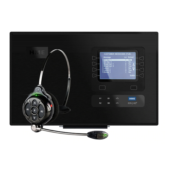
EQUIPMENT DESCRIPTION The EOS|HD is an audio system primarily for use at quick-service restaurants. The equipment shown below is standard with each EOS|HD. Optional equipment can be ordered from your local dealer. As you unpack the EOS|HD, check the packing list for each item to verify receipt of all equipment and quantities listed. -
Page 10: Base Station Features
Base Station Features The base station is the electronic heart of the EOS|HD. It contains the circuitry through which all functions of the drive-thru audio system are channeled. External base station features are shown in Figures 2 and 3. Internal connectors and controls are shown in EOS|HD. -
Page 11: Rear And Side Panels
1.1.2 Rear and Side Panels Cabinet latches Antenna connectors Reset switch Screw holes (recessed) for mounting on wall Figure 3. Base station rear panel features When both of the cabinet latches, on top of the cabinet are pressed down at the same time, the cabinet can be opened by pulling forward and down. -
Page 12: Headset Features
Headset Features 1.2.1 Controls and Indicators Power Power button light Volume-up button Channel “A2” Transmit Channel “A1” button light button Channel “B” button Volume-down button Figure 4. Headset control buttons and indicator lights Power On Press and release the power button. A voice message in the headset will say “headset #, battery full/half/low”... -
Page 13: Correct Wearing Of Headsets
1.2.2 Correct Wearing of Headsets Wear the headset with the microphone on your right or left side next to your mouth. Adjust the headband and microphone boom as needed. Hold microphone boom here to adjust microphone position Figure 5. Correct wearing of the headset 1.2.3 Battery Removal and Replacement Battery-release... -
Page 14: Battery Charger
Battery Charger 1.3.1 Battery Charger Power Adapter for Use in the United States Plug the cord from the +5VDC power adapter into the top of the battery charger as shown in Figure 7, and then plug the power adapter into an electrical outlet. Figure 7. -
Page 15: Battery Charging
1.3.3 Battery Charging Charge up to four batteries while you are installing the other equipment. Charging time is about 2.5 hours. When the batteries are fully charged, install them in the headset as shown in section 1.2.3. Procedure: Insert batteries in the charging ports for charging. The batteries can only go into the charging ports one way. -
Page 16: Preparation For Installation
In the event of an electrical power outage — such as from a lightning storm or power generator failure, if you experience problems with your HME equipment after the electricity comes on again, unplug the equipment and wait 15 seconds, then plug it back in. -
Page 17: Radio Frequency (Rf) Interference
5 and 7 PM. Note the following symptoms carefully to determine the possible cause of interference. If you need help; in the USA call HME Technical Support at 1-800-848-4468, outside the USA, call your local HME representative. -
Page 18: Equipment Installation
If using a power source other than that supplied by HME, the power source must provide 24 volts DC regulated to +/-5%, be capable of supplying a minimum of 50 watts of power and be “LPS”... -
Page 19: Figure 11. Typical Tandem, Y-Lane And Dual Drive-Thru Layouts
If outside coverage is not needed, mounting the base at locations #3, #4 or #5 is best. Headset signals from most work areas would thereby require no wall penetration. Other work and seating areas may require signals to penetrate one wall. In this case, the remote antenna kit can be used. -
Page 20: Install Antennas On Base Station
Figures 28-38. Note: If using a power source other than that supplied by HME, it must provide 24 volts DC regulated to +/-5%, be capable of supplying a minimum of 50 watts of power and be “LPS” rated for safe operation of the unit. The power source must meet all applicable local regulatory requirements. -
Page 21: Register Headsets To Base Station
3.1.3 Register Headsets to Base Station Before you permanently mount the base station on the wall, you must register the headsets to the base station, so they can be used in a walk test to determine where the base station should be mounted for the best reception and transmission to/from all the areas where they will be used. - Page 22 You can continue pressing the Back button until you return to the MAIN MENU or LANE STATUS display. If you have any problems registering the headsets: In the USA, call HME Technical Support at 1-800-848-4468. Outside the USA, call your local HME representative for assistance.
-
Page 23: Walk Test For Best Transmission/Reception
3.1.4 Walk Test for Best Transmission/Reception Before permanently mounting the base station, do a walk test with the base station at various locations until the best possible transmission/reception is found. To check transmission/reception, have two people walk around the area where the headsets will be used, pressing the B button to communicate with each other, walking past the menu board to test reception when using speed-team operation. -
Page 24: Figure 15. Remote Antenna Mounting On Wall Bracket
Hold the enclosed antenna mounting bracket against the wall at the desired mounting location and mark the wall through the two screw holes in the bracket. It may be necessary to mount the antenna high enough to avoid a safety hazard or possible damage to the antenna. -
Page 25: Cable Pulling
Cable Pulling CAUTION: If you do not use the HME audio cable, be sure the speaker/microphone wires you use are a twisted pair. For full-duplex installations, the speakers and microphones must use separate cables or audio feedback will occur. Never run high-voltage cables in the same conduit with audio or loop cables. -
Page 26: Install Dm5 Microphone
3.3.1 Install DM5 Microphone Typical DM5 Microphone installation involves placement of the microphone in its molded foam enclosure and mounting it inside the upper compartment of the speaker post, connecting it to the microphone/speaker cable wires from the drive-thru audio system, and filling the empty space behind the unit with acoustic foam (not provided). -
Page 27: Install Sp10 Speaker
3.3.2 Install SP10 Speaker Strip approximately 1 inch (25.4 mm) of insulation from the end of the speaker cable, and ¼ inch (6.35 mm) of insulation from each of the two cable wires, but do not tin the wires. Connect the speaker cable wires to the connector plug as shown in Figure 19. -
Page 28: Figure 21. Attach Brackets To Speaker
If using the optional mounting brackets: Attach the brackets to the screw inserts on the sides of the speaker unit with the two Phillips (crosspoint) screws provided as shown in Figure 21. Figure 21. Attach brackets to speaker Hold the front of the speaker centered against the speaker grill of the menu board or speaker post. -
Page 29: Optional Sp2000A Speaker/Microphone Installation
Optional SP2000A Speaker/Microphone Installation The installation described below is for typical mounting of the SP2000A directly against the inside of the speaker grill. If it needs to be mounted at an angle, or at a distance from the speaker grill, its base can be bolted to a horizontal surface. Installation of this speaker is not recommended, except for half duplex systems. -
Page 30: Optional External Vehicle Detector Installation
Optional HME Vehicle Detector Board (VDB) Installation To install an HME VDB in the base station, follow the instructions below. Note: In tandem systems, two VDBs will be installed in the base station, one at the “VDB LANE 1”... -
Page 31: Base Station Settings
BASE STATION SETTINGS Settings Status The LANE STATUS display shows current, lane-related status information. It also lists the HME Technical Support toll-free phone number to call for service. The date and time are shown at the bottom of the screen. Note:... -
Page 32: Basic Installer Setups
Basic Installer Setups To access the Installer Setup mode, you must have an installer password. If you have an installer password, proceed as follows: Press the Menu button on the LANE STATUS display to access the MAIN MENU. Press the More button on the MAIN MENU to access the ADVANCED MENU. Press the Installer setup button on the ADVANCED MENU to access the ENTER INSTALLER PASSWORD display. -
Page 33: Lane Configuration
4.2.1 Lane Configuration To set up the base station for the appropriate drive-thru lane configuration, press the Configure Lane button on the INSTALLER SETUP display to select Single, Single/A2, Dual/Y or Tandem. If you change this setting, you must press the Back button for the base to automatically reset itself and save the setting. -
Page 34: Speaker Post
4.2.3 Speaker Post Select Speaker post on the INSTALLER SETUP display to access the SPEAKER POST display, to make the necessary outside speaker/microphone settings. Note: In multiple-lane configurations, the SPEAKER POST display will be divided by Lanes. Settings will be similar to those shown for single lane. -
Page 35: Clearsound
Diagnostics button on the INSTALLER SETUP display. Note: Diagnostics are typically performed with guidance from HME Technical Support. On the DIAGNOSTICS display, you can press the More button to see additional tests on the ADVANCED DIAGNOSTICS display. On the left side of either display, press the button for the test to be performed. -
Page 36: Advanced Installer Setups
Advanced Installer Setups To perform the following advanced installer setups, press the More button on the INSTALLER SETUP display to access the ADVANCED INSTALLER SETUP display. 4.3.1 Phone If a telephone is connected to the base station, to be used for telephone orders, the system must be set up for telephone operation. -
Page 37: Line In/Out Routing
4.3.2 Line In/Out Routing If an external audio source is connected to the base station line input, on the ADVANCED INSTALLER SETUP display press the Line In/Out routing button. Press the Line In to: button to select Inbound for the audio from the external source to be heard in headsets and ceiling speakers, or wherever inbound audio would normally be heard. -
Page 38: Vehicle Tone
4.3.4 Vehicle Tone To set up an alert tone to be heard in all headsets when a vehicle arrives in the drive- thru lane, press the Vehicle tone button on the ADVANCED INSTALLER SETUP display, and then, on the VEHICLE PRESENT TONE display, press the Vehicle (on). -
Page 39: Restore Defaults
4.3.7 Restore Defaults To erase all your installer settings and return the base station to its factory settings, press the Restore factory defaults button on the ADVANCED INSTALLER SETUP display, and then, if you are sure you want to change all settings back to factory defaults, press the Default button on the RESTORE FACTORY DEFAULTS display. -
Page 40: Network Settings
Network Settings If the base station is connected to a computer network for remote access, you must enter the network data based on information from your IT support. To do this, select the Menu button on the LANE STATUS display and then select More on the MAIN MENU. Press the Network button on the ADVANCED MENU display, to open the NETWORK SETTINGS display. - Page 41 IP Address – the internet protocol address of the base, used to identify the base on the local network. To edit this setting, press the IP Address button and then, on the EDIT STATIC IP ADDRESS display, use the ◄ and ► buttons to move the highlight to each number you would like to change, and press the + or −...
-
Page 42: Advanced Network Settings
Static DNS – Typically, DNS addresses are automatically provided by the DHCP server, if the DHCP is enabled and Static DNS is disabled −(off). If Static DNS is enabled, ✔ (on), it overrides the DNS1 and DNS2 addresses supplied by the DHCP server, in favor of the static addresses edited on these menus. - Page 43 + and − buttons to change the number in the highlighted box. Data port – This port is used for sending HME-supported commands to the base over a TCP/IC socket. The port value is 3255, but can be changed if necessary, or set at 0 to disable the port.
- Page 44 Telnet port – This port is reserved for use by HME Technical Support. Press the More button on the ADVANCED NETWORK SETTINGS display to access the BOOTLOADER NETWORK INFO display. Note: Bootloader information is used by HME Technical Support.
-
Page 45: Email / Texting
4.4.3 Email / Texting The base is capable of sending emails to store managers when alert conditions are triggered in the store. For this feature to be used, email settings must be entered, based on network information provided by IT support. To edit email settings, press the Emails button on the ADVANCED NETWORK SETTINGS display. - Page 46 Email Addresses – The Source Address is pre-set to hme-base6200-XXXXXX@hme.com. This will be the address shown in the “From:” line on alert emails sent to selected destinations. Destination email addresses are those to which alert emails will be ✔...
-
Page 47: User Settings
User Settings User settings are for routine drive-thru operation. After you make the initial settings, store personnel can change the settings as needed. To access the user settings, press the Menu button on the LANE STATUS display. Routine user settings are accessed from the MAIN MENU. -
Page 48: Operator Mode
4.5.2 Operator Mode The Operator Mode provides a Speed Team setting. In Speed Team operation, audio and vehicle detection are disabled at the order point. Speed Team Operation To set up Speed Team operation, select Menu on the LANE STATUS display and then select Operator mode on the MAIN MENU. -
Page 49: Message Center
4.5.3 Message Center The Message Center is a central point at which messages can be set up to be triggered by various events during designated time periods, to be sent to customers at the speaker post or to crew members via headsets or ceiling speakers. Some messages are pre-named and pre-recorded. - Page 50 MESSAGE CENTER MESSAGES NAME CONTENT All Day 1 Not pre-recorded. All Day 2 Not pre-recorded. Breakfast 1 Not pre-recorded. Breakfast 2 Not pre-recorded. Lunch 1 Not pre-recorded. Lunch 2 Not pre-recorded. Snack 1 Not pre-recorded. Customer Greeter messages are triggered Snack 2 Not pre-recorded.
- Page 51 1. Customer Greeter Message Settings To set up the time periods and locations for Customer Greeter messages to be played, or to name and/or record Customer Greeter messages, press the Menu button on the base station LANE STATUS display and then, on the MAIN MENU press the Message Center button.
- Page 52 Turn Message On/Off To turn the selected message on or off, press the Message button on the EDIT CUSTOMER GREETER display to (on) or −(off). highlight either ✔ Press the Back button to save this setting. Review or Record Message To review the existing selected message, or to record a new message, press the Review/Record button on the EDIT CUSTOMER GREETER display.
- Page 53 Message Schedule To choose the schedule for the selected message, press the Schedule button on the EDIT CUSTOMER GREETER display. On the SCHEDULE CUSTOMER GREETER display, press the button for the day you want the selected message to be played. On the SELECT SCHEDULE TIMES display, select the time period when you want the selected message to play by pressing the ▲(up) and ▼(down) buttons to scroll through the 12 available time periods.
- Page 54 Message Playback Settings To edit where the selected Customer Greeter message will be heard (in addition to the speaker post), press the Settings button on the EDIT CUSTOMER GREETER display. Note: Customer Greeter messages are always directed to the drive-thru speaker in addition to these settings.
-
Page 55: Reminder Message Settings
2. Reminder Message Settings To set up the time periods and locations for Reminder messages to be played, or to name and/or record Reminder messages, press the Menu button on the base station LANE STATUS display and then, on the MAIN MENU press the Message Center button. - Page 56 Turn Message On/Off To turn the selected message on or off, press the Message button on the EDIT REMINDER MESSAGE display to (on) or −(off). highlight either ✔ Press the Back button to save this setting. Review or Record Message To review the existing selected message, or to record a new message, press the Review/Record button on the EDIT REMINDER MESSAGE display.
- Page 57 Message Priority Reminder messages can be assigned a high or low priority. To set message priority, press the Priority button on the EDIT REMINDER MESSAGE display to highlight either High or Low. Press the Back button to save this setting. Note: If the priority is set Low, the message may play to completion or be terminated by either...
- Page 58 Message Playback Settings Routing − To choose where the selected Reminder message will be heard, press the Settings button on the EDIT REMINDER MESSAGE display, and then press the Headsets button on the EDIT REMINDER SETTINGS display. For multiple-lane operations, Appendix, Reminder Messages.
-
Page 59: Alert Message Settings
3. Alert Message Settings To set up the time periods and locations for Alert messages to be played, or to name and/or record Alert messages, press the Menu button on the base station LANE STATUS display and then, on the MAIN MENU press the Message Center button. Press the Alert messages button on the MESSAGE CENTER MENU. - Page 60 Turn Message On/Off To turn the selected message on or off, press the Message button on the EDIT ALERT MESSAGE display to highlight (on) or −(off). either ✔ Press the Back button to save this setting. Review or Record Message To review the existing selected message, or to record a new message, press the Review/Record button on the EDIT ALERT MESSAGE display.
- Page 61 Message Priority Alert messages can be assigned a high or low priority. To set message priority, press the Priority button on the EDIT ALERT MESSAGE display to highlight either High or Low. Press the Back button to save this setting. Note: If the priority is set Low, the message may play to completion or be terminated by either...
- Page 62 Message Playback Settings Routing − To choose where the selected Alert message will be heard, press the Settings button on the EDIT ALERT MESSAGE display, and then press the Headsets button on the EDIT ALERT SETTINGS display. For multiple-lane operations, Appendix, Alert...
- Page 63 Delay − To set a delay after the Alert message is triggered until it begins playing, press the Delay button. On the DELAY BEFORE PLAY display, use the ◄ or ► button to move the highlight left or right in the Delay field for minutes and seconds (MM:SS) , and use the + and −...
- Page 64 Alert Message Email To compose an email message to be sent to designated recipients when the selected Alert is triggered, select Message Text on the EDIT ALERT MESSAGE display. To edit the email text, on the Message Text display, use the Erase button to clear characters if there is a current email you want to change.
-
Page 65: Schedule Times
4. Schedule Times To set up all the time periods during each day, in which all Message Center messages can be scheduled, press the Menu button on the base station LANE STATUS display and then, on the MAIN MENU press the Message Center button. -
Page 66: Volume Adjustments
4.5.4 Volume Adjustments To adjust the volume of inbound and outbound audio, alert tones and message repeater messages, on the base station LANE STATUS display, select Menu and then, on the MAIN MENU select Volume adjust. Press the button on the left side of the VOLUME MENU to select which volume you want to adjust. -
Page 67: Register Headsets
To register headsets to the base station, see Section 3.1.3. 4.5.6 Service For HME Technical Support contact information, select Menu on the LANE STATUS display and then select Service on the MAIN MENU. -
Page 68: Store Settings
4.5.7 Store Settings Store settings are crucial to drive-thru operation. After you make the initial settings, they can be changed by store managers or other authorized personnel. After you have made all store settings, set up a password to control access to store settings, and give the password to the store manager. - Page 69 Set Store Hours To set the store hours for any or every day, press the Set store hours button on the STORE SETTINGS display. On the STORE HOURS display, press the button next to the day you would like to change.
- Page 70 Edit Schedule Times Up to 12 Schedule Times can be set to establish periods in which messages can be played from the Message Center. Schedule Times can be edited as needed. To make changes to the Schedule Times, press the Edit schedule times button on the STORE SETTINGS display.
- Page 71 Set Password When you have completed all the other Store Settings, set up a user password. When the installation is finished, be sure to give the password to the store manager. To set a password for the first time, press the Set password button on the STORE SETTINGS display.
- Page 72 VAA Settings VAA settings can be adjusted to eliminate echo, feedback or fluctuating inbound audio levels. To turn the VAA feature on/off, or to adjust VAA levels, press the More button on the STORE SETTINGS display. On the ADVANCED STORE SETTINGS display, press the VAA button.
- Page 73 Restore Installer Settings After the initial installer settings have been made, store personnel can customize adjustments to settings. After doing so, they can always return the base station to its original installer settings by pressing the Restore installer settings button on the ADVANCED STORE SETTINGS display, and then pressing the Restore button on the RESTORE INSTALLER SETTINGS display.
-
Page 74: Lcd Contrast
Phone Headset If there is an HME Telephone Interface connected to your base station, you can assign one headset to receive incoming telephone calls. To do this, press the Phone headset button on the ADVANCED STORE SETTINGS display. On the SELECT PHONE HEADSET display, use the ◄... -
Page 75: Installer Setup
4.5.10 Diagnostics Only press the Diagnostics button if you experience a problem with EOS|HD operation and have to call HME Technical Support. The Technical Support representative will guide you through the automated diagnostics. If this is necessary, select Menu on the base station STATUS display and then press the More button on the MAIN MENU. -
Page 76: Pc Navigation
PC Navigation If your EOS|HD was set up to operate on a network, all of the same settings that can be made on the base station can also be made from your PC, using a web browser. Refer to Section 4.4, Network Settings, to configure the base with the proper Network settings according to information from your IT department. - Page 77 Save installer settings and Restore factory settings. Reports – allows you to view Message Center settings and headset statistics reports. Diagnostics – provides information that may be used by HME Technical Support to diagnose problems. Service – displays all version information and contact information, in case you...
-
Page 78: System Functional Check
SYSTEM FUNCTIONAL CHECK ACTION RESULT Plug base station power adapter into electrical System power is on. Base station lights are on. outlet. Go outside (or have someone else go) to the speaker/microphone and do the following. Audio should be heard at outside speaker. Push button A1 or A2 and speak into headset microphone. -
Page 79: Routine Operation
ROUTINE OPERATION The EOS|HD can be operated in Hands-Free (HF), Auto-Hands-Free (AHF), B-channel Hands-Free (BHF) or Push-To-Talk (PTT) modes. A full-duplex system supports HF, AHF, BHF and PTT operation. In HF, AHF and BHF operation, communication can be transmitted and received at the same time, as in a normal telephone conversation. -
Page 80: Single-Lane Operation (One Speaker Post In One Lane)
Single-Lane Operation (one speaker post in one lane) Hands-Free (HF) Mode: With the power off, press and hold the volume-up Λ and B buttons while you press and release the power button to turn the headset on in the HF mode. The headset will remember this setting. -
Page 81: Dual-Lane Operation (Two Lanes With One Speaker Post In Each Lane)
Dual-Lane Operation (two lanes with one speaker post in each lane) Hands-Free (HF) Mode: With the headset power off, press and hold the volume-up Λ and B buttons while you press and release the power button to turn it on in the HF mode. The headset will remember this setting. -
Page 82: Tandem Operation (Two Speaker Posts In One Lane)
customer at the speaker post or menu board if that lane is selected. Use the volume-up Λ and down V buttons to adjust the customer’s voice level in the headset if necessary. Touch and hold the A1 button to speak to a customer in Lane 1, or A2 to speak to a customer in Lane 2. -
Page 83: Internal Communication
Auto Hands-Free (AHF) Mode (Only Order Taker #1): Order Taker #1 only, with the headset power off, press and hold the volume-up Λ and A1 button while you press and release the power button to turn it on in the AHF mode. -
Page 84: Speed-Team Operation
Speed-Team Operation Speed team operation is used during high-volume times. An order taker wearing a headset relays orders from outside into the store, using button A1, A2 or B. Note: Speed teams are only used in single or dual-lanes, not in tandem drive-thrus. CAUTION: With Speed Team ✔... -
Page 85: In Case Of Problems
NOTE: If the inbound level is too low, you will not hear the customer. Power may be off at base station. Be sure HME logo and other lights on base station are lit. No sound is heard in headset when you press Check circuit breaker for building. - Page 86 If it still is not working, call HME.* “Registration failed” Base station power not on. Be sure HME logo and other lights on base station are lit. If no light is lit, be certain power adapter is plugged into message heard in headset.
-
Page 87: Figure 26. Base Station Internal Connectors And Controls
Figure 26. Base station internal connectors and controls ANT1 antenna connector ANT2 antenna connector Switcher board connectors, J4-Lane 1 Switcher board connectors, J13-Lane 2 Ethernet connector, J12 Power connector, J3 Ceiling speaker connector, J1-Lane 1, J11-Lane 2 Outside speaker/microphone connector, J6-Lane 1, J14-Lane 2 Line in/out connector, J7-Lane 1, J16-Lane 2 Early warning/alert connector, J9-Lane 1, J19-Lane 2 Remote switch connector, J2... -
Page 88: To Set Base Station For Spanish Or French Language Operation
TO SET BASE STATION FOR SPANISH OR FRENCH LANGUAGE OPERATION If the base station is returned to its factory default settings, it will be set for English language operation. To change the language to Spanish or French, make the following selections on the base station display. Press the buttons indicated by arrows in the order of the numbered displays. -
Page 89: Equipment Specifications
EQUIPMENT SPECIFICATIONS Base Station Voltage input 24VDC ±2.5V AC current input 2.5A maximum Audio distortion 5% maximum level Outside speaker output 3 watts RMS into 8 ohms Ceiling speaker power 3 watts RMS into 8 ohms TX/RX frequency 2400MHz – 2483.5MHz Dimensions 9.75”H x 13”W x 3.5”D (248 mm x 330 mm x 89 mm) -
Page 90: Block Diagram
10. BLOCK DIAGRAM Figure 27. Typical EOS | HD Base Station block diagram... -
Page 91: Base Interface Description
11. BASE INTERFACE DESCRIPTION Audio Circuit Board 11.1 J1 – Ceiling Speaker In/Out, Lane 1 J7 – Line In/Out, Lane 1 J1,1 Ground J7,1 Line out J1,2 /A1 Talk J7,2 Ground J1,3 Relay 1 Common J7,3 Line in J1,4 Relay 1 Normally Open J7,4 Ground J1,5... -
Page 92: Switcher Circuit Board
J15 – Telephone Interface J19 – Early Warning / Alert, Lane 2 J15,1 Telephone audio into base J19,1 Early warning J15,2 12V J19,2 Ground J15,3 /A2 talk J19,3 Not used J15,4 /B2 talk J19,4 Ground J15,5 Car 2 J19,5 Alert in J15,6 Vehicle detect in J20 –... -
Page 93: Wiring Diagrams
12. WIRING DIAGRAMS Full-Duplex Drive-Thru System with VDB but no Switcher Board Page 86, Figure 28 — (Connections for Lane 1 or Single Lane) Page 87, Figure 29 — (Connections for Lane 2 of Dual/Y-Lane or Tandem) Full-Duplex Drive-Thru System with VDB, Switcher Board and IC300 Intercom Page 88, Figure 30 —... - Page 94 Figure 28.
- Page 95 Figure 29.
- Page 96 Figure 30.
- Page 97 Figure 31.
- Page 98 Figure 32.
- Page 99 Figure 33.
- Page 100 Figure 34.
- Page 101 Figure 35.
- Page 102 Figure 36.
- Page 103 Figure 37.
- Page 104 Figure 38.
-
Page 105: Appendix
13. APPENDIX Dual-Lane Installer Setup 13.1 13.1.1 Split B For Dual/Y and Tandem operations only, the Split B feature is available. If set to Combined, Lane 1 and Lane 2 operators can communicate over B channel. If set to Split, Lane 1 operators can only communicate over the Lane 1 - B channel, and Lane 2 operators can only communicate over the Lane 2 - B channel. -
Page 106: Dual-Lane Message Center Settings
Dual-Lane Message Center Settings 13.2 13.2.1 Customer Greeter Messages In dual-lane operations, Customer Greeter messages can be set to play in Lane 1, Lane 2, or both Lanes 1 & 2. To do this, press the Edit button on the CUSTOMER GREETER display, and then press the Event button to highlight Lane 1, Lane 2 or Lane 1/2.
Need help?
Do you have a question about the EOS HD and is the answer not in the manual?
Questions and answers