Table of Contents
Advertisement
Advertisement
Table of Contents
Troubleshooting

Related Manuals for BONFIGLIOLI Agile


Summary of Contents for BONFIGLIOLI Agile
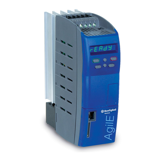
- Page 1 Agile Operating Instructions Frequency inverter 230 V / 400 0.09 kW ... 11 kW...
-
Page 3: Table Of Contents
2.10.4 Handling and installation ................... 20 2.10.5 Electrical connections ....................20 2.10.5.1 The five safety rules ................... 21 2.10.6 Safe operation ......................21 2.10.7 Maintenance and service/troubleshooting ..............22 2.10.8 Final decommissioning ....................22 Agile This document 06/2013 Operating Instructions... - Page 4 Selection of Data sets ..................54 6.1.1.2 Menu for communication setup ................55 6.1.2 Motor control with operator panel ................56 6.1.3 Set a parameter to the factory setting ................ 60 6.1.4 Restrict the scope of operation ................... 60 Agile Operating Instructions 06/2013 This document...
- Page 5 Start device test via control software or bus system ..........120 7.2.3.5 Automatic device test after error switch-off............121 7.2.3.6 Fan test ......................121 Operational Behavior ....................122 7.3.1 Control ........................122 7.3.2 Starting behavior ....................123 7.3.3 Stopping behavior ....................127 Agile This document 06/2013 Operating Instructions...
- Page 6 Reference value reached ................... 190 7.6.5.4 Flux forming finished ..................191 7.6.5.5 Release brake ....................192 7.6.5.6 Current limitation ..................... 192 7.6.5.7 External fan ..................... 192 7.6.5.8 Warning mask ....................192 7.6.5.9 Warning mask, application ................195 Agile Operating Instructions 06/2013 This document...
- Page 7 7.10.7 V-belt monitoring ....................250 7.10.8 Traverse function ....................250 7.10.9 System data ......................253 7.10.10 Service interval monitoring ................... 253 7.10.11 Copy parameters ....................253 7.10.11.1 Copying using the operator panel ..............254 Agile This document 06/2013 Operating Instructions...
- Page 8 AGL202 (3~:5.5 to 7.5 kW, 1~:3.0 kW, 230 V) ............282 11.2.5 AGL402 (0.25 to 2.2 kW) ..................283 11.2.6 AGL402 (3.0 to 11.0 kW) ..................284 11.2.7 Increase of switching frequency ................285 11.3 Control electronics ....................286 Agile Operating Instructions 06/2013 This document...
- Page 9 DIN rail (This assembly set is not included in delivery.) ..........324 12.9.4.1 Size 1 (3~: 0.18 kW to 2.2 kW; 1~: 0.09 kW to 1.1 kW) ........324 ERROR PROTOCOL ..................325 13.1 Error list ....................... 325 Agile This document 06/2013 Operating Instructions...
- Page 10 14.2 Controller status ....................335 14.3 Warning status and warning status application ..........336 PARAMETER LIST ..................339 15.1 Actual values (Menu Actual) ................339 15.2 Parameters (Menu PARA) ..................343 INDEX ........................354 Agile Operating Instructions 06/2013 This document...
-
Page 11: General Information About The Documentation
General information about the documentation General information about the documentation For the series of devices AGL (Agile) is for the safety-related commissioning and opera- tion to be complied with the following documentation: This Operating instructions • • Application manual “Functional Safety Agile”... -
Page 12: This Document
Warranty and liability BONFIGLIOLI VECTRON GmbH would like to point out that the contents of this user manual do not form part of any previous or existing agreement, assurance or legal relationship. Neither are they intended to supplement or replace such agreements, assurances or legal relationships. Any obligations of the manufacturer shall solely be based on the relevant purchase agreement which also includes the complete and solely valid warranty stipulations. -
Page 13: Obligation
Copyright In accordance with applicable law against unfair competition, this user manual is a certificate. Any copyrights relating to it shall remain with BONFIGLIOLI VECTRON GmbH Europark Fichtenhain B6 47807 Krefeld Germany These user manual is intended for the operator of the frequency inverter. Any disclosure or copying of this document, exploitation and communication of its contents (as hardcopy or electronically) shall be forbidden, unless permitted expressly. -
Page 14: General Safety Instructions And Information On Use
Experts must be familiar with the applicable government work safety directives, accident prevention regulations, guidelines and generally accepted rules of technology in order to assess the operationally safe condition of the frequency inverter. Agile Operating Instructions 06/2013... -
Page 15: Designated Use
The manufacturer shall not be held liable for any damage resulting from such misuse. The sole risk shall be borne by the operator. 2.3.1 Explosion protection The frequency inverter is an IP 20 protection class device. For this reason, use of the device in explo- sive atmospheres is not permitted. Agile Designated use 06/2013 Operating Instructions... -
Page 16: Residual Risks
Safety and warning signs at frequency inverter Comply with all safety instructions and danger information provided on the frequency inverter. • Safety information and warnings on the frequency inverter must not be removed. • Agile Operating Instructions 06/2013 Residual risks... -
Page 17: Warning Information And Symbols Used In The User Manual
Meaning Symbol Meaning General hazard Suspended load Electrical voltage Hot surfaces 2.6.3 Prohibition signs Symbol Meaning No switching; it is forbidden to switch the machine/plant, assembly on Agile Warning information and symbols used in the 06/2013 Operating Instructions user manual... -
Page 18: Personal Safety Equipment
2.6.7 ESD symbol Symbol Meaning ESD: Electrostatic Discharge (can damage components and assemblies) 2.6.8 Information signs Symbol Meaning Tips and information making using the frequency inverter easier. Agile Operating Instructions 06/2013 Warning information and symbols used in the user manual... -
Page 19: Directives And Guidelines To Be Adhered To By The Operator
Only use the frequency inverter if the rated connection and setup values specified by the manu- • facturer are met. Provide appropriate tools as may be required for performing all work on the frequency inverter • properly. Agile Directives and guidelines to be adhered to by the 06/2013 Operating Instructions operator... -
Page 20: Organizational Measures
Optional components for the frequency inverter must be used in accordance with their designated • use and in compliance with the relevant documentation. 2.10.2 Use in combination with third-party products Please note that BONFIGLIOLI VECTRON GmbH will not accept any responsibility for compatibility • with third-party products (e.g. motors, cables or filters). •... -
Page 21: The Five Safety Rules
Before commissioning and the start of the operation, make sure to fix all covers and check the • terminals. Check the additional monitoring and protective devices according to EN 60204 and ap- plicable the safety directives (e.g. Working Machines Act or Accident Prevention Directives). Agile Organizational measures 06/2013 Operating Instructions... -
Page 22: Maintenance And Service/Troubleshooting
In any case, comply with any applicable national disposal regulations as regards envi- ronmentally compatible disposal of the frequency inverter. For more details, contact the competent local authorities. Agile Operating Instructions 06/2013 Organizational measures... -
Page 23: Device Overview
Device overview Device overview This chapter describes the characteristic of the Agile series. Inverter type and warning signs on the device • Determine the type of frequency inverter. • Verify that the rated input voltage corresponds to the local power supply. -
Page 24: Type Designation
Type designation Basic Type designation Series: AGL 202: inverter Agile 1xAC 200 – 15 %…240 V + 10 % 3xAC 200 – 15 %…240 V + 10 % AGL 402: inverter Agile 3xAC 360…480 V +/- 10 % Size (Power) -
Page 25: Software Version Identification
Device overview Software Version Identification The Software version plate is situated right from the memory card slot and left from the Control terminals. Agile Software Version Identification 06/2013 Operating Instructions... -
Page 26: Overview Of Components And Connection Terminals
The products for CANopen® communication comply with the specifications of the user organization CiA® (CAN in Automation). Install an interface adapter for connection of a PC. This enables configuration and monitoring using the PC software VPlus. Agile Operating Instructions 06/2013 Overview of components and connection... -
Page 27: Mechanical Installation
Mount the devices with sufficient clearance to other components so that the cooling air can circulate freely. Avoid soiling by grease and air pollution by dust, aggressive gases, etc. Suction intakes of fans may not be covered. Installation Mounting distance d > 100 mm Agile Safety 06/2013 Operating Instructions... -
Page 28: Size 1 (3~:0.18 Kw To 2.2 Kw; 1~: 0.09 Kw To 1.1 Kw)
Mechanical Installation 4.2.1 Size 1 (3~:0.18 kW to 2.2 kW; 1~: 0.09 kW to 1.1 kW) Valid for the following devices Frequency inverter Agile Agile Type Mains supply 1ph. 3ph. 3ph. Power -01 1 0.09 0.18 -02 1 0.12 0.25 0.25... -
Page 29: Size 2 (3~: 3.0 Kw To 5.5 Kw; 1~: 1.5 Kw To 2.2 Kw)
Mechanical Installation 4.2.2 Size 2 (3~: 3.0 kW to 5.5 kW; 1~: 1.5 kW to 2.2 kW) Valid for the following devices Frequency inverter Agile Agile Type Mains supply 1ph. 3ph. 3ph. Power -15 2 -18 2 -19 2 Dimensions Assembly Use screws M6. -
Page 30: Size 3 (5.5 Kw To 11.0 Kw)
Mechanical Installation 4.2.3 Size 3 (5.5 kW to 11.0 kW) Valid for the following devices Frequency inverter Agile Agile Type Mains supply 1ph. 3ph. 3ph. Power -19 3 -21 3 -22 3 -23 3 Dimensions 220 (+3) Assembly Use screws M6. -
Page 31: Electrical Installation
Electrical Installation Electrical Installation This chapter describes the electrical installation of the Agile series. Safety WARNING The electrical installation must be carried out by qualified electricians according to the general and regional safety and installation directives. The documentation and device specification must be complied with during installation. -
Page 32: Electrical Connections Overview
Keep the cables as short as possible; make sure that cables are installed properly using appropri- • ate cable clamps, etc. Contactors, relays and solenoids in the electrical cabinet are to be provided with suitable interfer- • ence suppression components. Agile Operating Instructions 06/2013 Electrical connections overview... - Page 33 Install the mains supply cable separate from the control and data cables and the motor cable. DC link connection The frequency inverter may be connected via the terminals "-" and "+" of terminal block X10 to fur- Agile ther - or ACTIVE-devices or to a common direct voltage source. Cables longer than 300 mm are to be shielded.
-
Page 34: Dimensioning Of Conductor Cross-Section
Consider the reduction of the maximum output voltage if a line choke is installed. The line choke must be installed between mains connection and input filter. BONFIGLIOLI provides applicable line chokes. Refer to chapter 12.4 “Line choke”. Input filter Input filters reduce the conducted radio-frequency interference voltage. -
Page 35: Typical Cross-Sections
4 mm² Connection on protective earth on mounting plate. Please note, that the mentioned typical cross sections do not consider other factors like fuses. Comply with applying local standards and applying branch standards. Agile Dimensioning of conductor cross-section 06/2013 Operating Instructions... -
Page 36: Mains Connection
: Only for in DC link connections. Comply with the notes on cable cross-sections in chapter 5.4 "Dimensioning of conductor cross- section". Cable cross-sections mm 0,2 … 4 (flexible cable with sleeve) Mains terminals: 0,2 … 6 (rigid cable) Agile Operating Instructions 06/2013 Mains Connection... - Page 37 Removing the jumper reduces interference immunity and increases the emitted interfer- ence. Interference immunity can be increased by means of external filters. Additional work for EMC conformity may be possible. Comply with the EMC information. Agile Mains Connection 06/2013 Operating Instructions...
-
Page 38: Motor Connection
When using pluggable terminals: Do not switch on the device while the plugs are dis- connected, the IP protection is only warranted with plugged terminals. BONFIGLIOLI recommends connecting the motor to the frequency inverter using shielded cables. • Connect the cable shield to PE potential properly, i.e. with good conductivity, on both sides. -
Page 39: Length Of Motor Cables, Without Filter
Electrical Installation 5.6.1 Length of motor cables, without filter Permissible length of motor cable without output filter Agile Agile Type unshielded cable shielded cable Mains supply 1ph. 3ph. 3ph. Power -01 1 0.09 0.18 -02 1 0.12 0.25 0.25 -03 1 0.18... -
Page 40: Motor Cable Length, With Output Filter Du/Dt
The frequency inverter must be suitable for the higher output cur- rent. This must be considered in the projecting phase. In the case of motor cable lengths exceeding 300 m, contact BONFIGLIOLI service. 5.6.4... -
Page 41: Brake Resistor
Do not cover the brake resistor. CAUTION Bonfiglioli Vectron recommends using a temperature switch. Depending on the selected resistor the temperature switch is integrated as a standard or optional available. A de- tailed list is included in Chapter 12.3 “Brake resistor”. The temperature switch discon- nects the frequency inverter from mains supply if the brake resistor is overloaded. - Page 42 Minimum Torque to tighten the screws: 0.5 Nm (4.6 lb-in) Maximum Torque to tighten the screws: 0,6 Nm (5,3 lb-in) NOTE BONFIGLIOLI provides suitable brake resistors. Refer to chapter 12.3 “Brake resistor”. For calculation of brake resistance refer to chapter 7.10.4.1 “Dimensioning of brake resistor”.
-
Page 43: Control Terminals Standard Connection
For evaluation of the motor thermo contact, parameter Operation Mode Motor-PTC See Chapter 7.4.6 "Motor temperature“. Via parameters 559, the logic evaluation at IN1D, IN2D, IN4D and IN5D is Digital inputs PNP/NPN changed. Agile Control terminals Standard connection 06/2013 Operating Instructions... - Page 44 Electrical Installation X13 1 X12 1 4 5 6 RJ45 1 2 3 4 5 +24 VDC OUT2D Potential free Agile Operating Instructions 06/2013 Control terminals Standard connection...
- Page 45 Op.Mode OUT3D (X11.6) OUT3D OUT3D signal IN: input, OUT: output, MFI: Multi-function input MFO: Multi-function output, D: digital, A: analog, F: frequency, PT: pulse train, RF: Repetition frequency, Op. Mode: Operation Mode Agile Control terminals Standard connection 06/2013 Operating Instructions...
-
Page 46: Circuit For Control Via Control Terminals
The motor is started via the operator panel. The circuit shows the input signals required as a mini- mum and the control terminals in factory settings. 1.5 mm max. 2.5 mm VDC out: Voltage output Enable Agile Operating Instructions 06/2013 Control terminals Standard connection... -
Page 47: Further Setting Options For Control Terminals
Electrical Installation 5.7.3 Further setting options for control terminals The block diagram only shows a selection of possible uses of the inputs and outputs. Agile Control terminals Standard connection 06/2013 Operating Instructions... -
Page 48: Evaluation Logic Of Digital Inputs
PNP (active: 24 V) Terminal Input Operation Mode MFI2 Low-switching (with negative sig- digital NPN (active: 0 V) nal).Factory setting. X12.4 MFI2 High-switching (with positive signal). digital PNP (active: 24 V) Agile Operating Instructions 06/2013 Control terminals Standard connection... -
Page 49: Overview Of Voltage Inputs And Outputs
− The relay output X10 is controlled only if mains voltage is switched on. − The heat sink fan and the internal fan are controlled only if mains voltage is switched on. Agile Control terminals Standard connection 06/2013... -
Page 50: Installation Notes According To Ul508C
For an installation according to UL508c the devices are only allowed to be used in environments ac- cording to Pollution Degree 2. According to UL508c Warn- or Marking labels are not allowed to be removed. Agile Operating Instructions 06/2013 Control terminals Standard connection... -
Page 51: Commissioning
The frequency inverter may only be commissioned by qualified staff. Prior to commissioning, all covers must be fixed, all standard equipment components of the frequency inverter must be installed, and the terminals must be checked. Procedure: Chapter 5.7.1 5.7.2 6.1.2 Agile Control terminals Standard connection 06/2013 Operating Instructions... -
Page 52: Operator Panel
Guided commissioning also for the available communication interfaces. Full For first commissioning. Entry and measurement of motor data. Motor Only motor data measurement. Buscon For commissioning of a communication interface. Copy Copy parameters by means of a memory card. Agile Operating Instructions 06/2013 Operator panel... - Page 53 Commissioning Agile Operator panel 06/2013 Operating Instructions...
-
Page 54: Selection Of Data Sets
Contains a parameter different values in the data set, the selection of the parameter will automatically show data set 1. If the data sets differ they can only be be changed individually via Keypad. Agile Operating Instructions 06/2013 Operator panel... -
Page 55: Menu For Communication Setup
Commissioning 6.1.1.2 Menu for communication setup Agile Operator panel 06/2013 Operating Instructions... -
Page 56: Motor Control With Operator Panel
In the factory setting the reference frequency value can be positive (clockwise rotation) or negative (anticlock- wise rotation). 418 (factory setting 3.50 Hz) limits the setting Value “0” cannot be set if parameter Minimum Frequency range. Agile Operating Instructions 06/2013 Operator panel... - Page 57 2 The drive is stopped. The alternating display shows the reference frequency value and the message STOP. The selection Poti F is only available if the parameter 412 was set like Local/Remote described above. Agile Operator panel 06/2013 Operating Instructions...
- Page 58 492. In the factory setting the reference frequency Factory setting of parameter Reference frequency source 2 value can be set via operator panel (keypad). In the factory setting the reference percentage value can be positive or negative. Agile Operating Instructions 06/2013 Operator panel...
- Page 59 “JOG frequency” and 7.6.6.7 “Jog Start”. The selection JOG is available independent of the setting of parameter 412. cal/Remote The commands Start clockwise and Start anticlockwise have a higher priority than the start of the function JOG. Agile Operator panel 06/2013 Operating Instructions...
-
Page 60: Set A Parameter To The Factory Setting
After Setup the drive is operational. Select “Full” setup if the frequency inverter is commissioned for the first time. Select “Motor” setup if only the motor data are to be measured and other settings are not to be changed. Agile Operating Instructions 06/2013 First commissioning... -
Page 61: Overview
• Switch off enable at IN1D (X11.4) and IN2D (X11.5), if a circuit for control via control terminals is • installed. • Switch on the power supply. • Start commissioning (Setup) on operator panel. Agile First commissioning 06/2013 Operating Instructions... - Page 62 Select “Foc”. Control of a synchronous motor, for higher demands on speed or torque accuracy. In the case of control via operator panel: Select “Synch”. PMSM: Permanently magnetized synchronous motor. Agile Operating Instructions 06/2013...
- Page 63 Note If a BONFIGLIOLI motor is connected and the rated values have been confirmed, “Calc” instead of “tune” is displayed. In this case further motor parameters are not measured. The data is loaded and stored. If instead an auto-tuning should be done, use the arrow keys to switch from “Calc”...
- Page 64 The motor characteristics are set correctly for most of the applications with the default settings. In some cases optimization of the motor characteristics can be necessary or improve the performance significantly. The optimization possibilities are described in chapter 6.2.10. Agile Operating Instructions 06/2013...
-
Page 65: Start First Commissioning Of A Synchronous Motor
Select “UF”. IM: Induction machine (asynchronous motor). Control of an induction machine (asynchronous motor). For higher demands on speed or torque accuracy. In the case of control via operator panel: Select “Foc”. Agile First commissioning 06/2013 Operating Instructions... - Page 66 Rated current in A If a BCR or BTD motor of Bonfiglioli Vectron was selected, the follow- ing data are preselected based on the standstill torque and the rated current. If a BONFIGLIOLI motor is connected check and confirm the values.
- Page 67 Display ting option. Note If a BONFIGLIOLI motor is connected and the rated values have been confirmed, “Calc” instead of “tune” is displayed. If “calc” is selected, no further motor parameters are measured. The data is loaded and stored.
-
Page 68: Status Messages During Commissioning (Ss
The maximum reference voltage is indicat- ed on the nameplate of the frequency inverter. For an asynchronous motor, the calculated efficiency is in the limit range. SA002 Efficiency Check 370, 371 and 376. Rated Voltage Rated Current Rated Power Agile Operating Instructions 06/2013 First commissioning... - Page 69 13.3 "Troubleshooting". If errors or warning messages occur during operation, proceed according to the instructions in chap- ters 13.1.1 "Error messages" and 14.3 "Warning status and warning status application". Agile First commissioning 06/2013 Operating Instructions...
-
Page 70: Error Messages During Commissioning (Sf
13.3 "Troubleshooting". If errors or warning messages occur during operation, proceed according to the instructions in chap- ters 13.1.1 "Error messages" and 14.3 "Warning status and warning status application". Agile Operating Instructions 06/2013 First commissioning... -
Page 71: Check Direction Of Rotation
NOTE When using a synchronous motor (in example BCR-, BTD-motor from BONFIGLIOLI) the correct phase sequence must be complied with. A mix up of the phases leads to the loss of the correct motor control and typically a fault message. -
Page 72: Commissioning Without Setup
721 higher and 722 lower. Please note, Amplification 1 (|f|<P738) Integral Time 1 (|f|<P738) that 738 offers different settings of the speed controller for Speed Control Switch-Over Limit Agile Operating Instructions 06/2013 First commissioning... -
Page 73: Voltage Constant
Frequency 624 is set to approx. 5 % of the Rated frequency. The value can be reduced in most applica- limit tions. Bonfiglioli Vectron recommends to set up the 624 always > 2.5 % of the rated Frequency limit frequency and at least 1 Hz. Check your changes via the Scope function. -
Page 74: Commissioning Of A Communication Interface
EtherCAT doesn’t require parameterization at the frequency inverter. The settings are ® done for EtherCAT completely via the PLC. Selection is possible only if an optional communication module CM-PDPV1 is installed. Agile Operating Instructions 06/2013 Commissioning of a communication interface... - Page 75 P385 P276 (System bus at X12.5 and X12.6.) Profibus Parameter Display Profibus Node-ID Node ID Bus configuration, Profibus Node ID Deactivated P391 SETUP communication Agile Commissioning of a communication interface 06/2013 Operating Instructions...
- Page 76 Baudrate CAN interface setting (CM-CAN/X12). − Set the terminals X12.5 and X12.6 to system bus. − Set an optional communication module CM-CAN to sys- tem bus. Agile Operating Instructions 06/2013 Commissioning of a communication interface...
- Page 77 Modbus Parity Interface setting. Protocol (CM/X21). − Set the service interface X21 to Modbus. − Set an optional communication module CM-232 or CM- 485 to Modbus. Agile Commissioning of a communication interface 06/2013 Operating Instructions...
- Page 78 − Set an optional communication module CM-232 or CM- 485 to VABus. − Set the service interface X21 and an optional communi- cation module CM-232 or CM-485 to VABus. Agile Operating Instructions 06/2013 Commissioning of a communication interface...
- Page 79 If this was not successful, an error or timeout mes- sage might occur. RELOAD: Reload can be used to reload the default values. If this was not successful, an error or timeout message might occur. Agile Commissioning of a communication interface 06/2013 Operating Instructions...
-
Page 80: After First Commissioning
Factory setting. Control of direction of rotation (parameter Start Clockwise Start Anticlock- 69) and signal 87 via digital inputs. wise Start 3-Wire Ctrl. Further settings are applicable for control via bus system. Agile Operating Instructions 06/2013 After first commissioning... - Page 81 Technology Controller Analog Value MFI2A Electronic gear Fixed Frequency 2501 PLC-Output Frequency 1 Motorpot. via Digital Inputs 2502 PLC-Output Frequency 2 Keypad-Motorpot. (P492) Repetition Frequency Not all possible reference frequency sources are shown. Agile After first commissioning 06/2013 Operating Instructions...
- Page 82 P730 Torque limit P739 Power limit The Speed Control is always limited by the Minimum Frequency (P418) and Maximum Frequency (P419). P30 must be set to 410 (asynchronous motor) or 610 (synchronous motor). Agile Operating Instructions 06/2013 After first commissioning...
- Page 83 Reference Percentage reached P558 = 1 (output) Ixt-Warning (overload) Warning Heat Sink Temperature P554 Setting Frequency X13.6 Warning Inside Temperature P550 = 1 (digital) Warning Motor Temperature Warning, General (Not all functions are listed.) Agile After first commissioning 06/2013 Operating Instructions...
- Page 84 Abs. T (torque) (Not all functions are listed.) Via multifunction output (MFO1), output analog value: Set MFO1 as analog output. Set the voltage range (0…22 V) for output. Select the value to be output. Agile Operating Instructions 06/2013 After first commissioning...
- Page 85 P62 IN[]D: Increase reference value. P63 IN[]D: Reduce reference value. Keypad motor potentiometer: ▲: Increase reference value. ▼: Reduce reference value. P473 Ramp for Motor potentiometer (2.00 Hz/s); limited to values from P420 to P423. Agile After first commissioning 06/2013 Operating Instructions...
- Page 86 P419 (maximum frequency) or of P519 (maximum PWM, -100 … 100% reference percentage) P652 and P653; for scaling P476 or P494: Repetition percentage The Speed Control is always limited by the Minimum Frequency (P418) and Maximum Frequency (P419). Agile Operating Instructions 06/2013 After first commissioning...
- Page 87 P654 (scaling frequency) (P419) P475 or P492: Repetition frequency P476 or P494: Repetition percentage 25000 [Hz] IN2D (P654) The Speed Control is always limited by the Minimum Frequency (P418) and Maximum Frequency (P419). Agile After first commissioning 06/2013 Operating Instructions...
- Page 88 The current during flux-formation (value of P781) is not impressed longer than this time. P781 Current during Flux-Formation (value: I Upon startup, this current value is impressed. The time for current impression is limited by P780. Nominal value of frequency inverter Agile Operating Instructions 06/2013 After first commissioning...
- Page 89 For state P68 and P69 = logic 1, a stopping behavior must be selected. For state P68 and P69 = logic 0, a stopping behavior must be selected. Nominal value of frequency inverter Agile After first commissioning 06/2013 Operating Instructions...
- Page 90 50 Hz). Motor temperature monitoring Evaluate thermo contact at MFI1 (X12.4): Thermo contact, P204: Warning only Thermo contact, P204: Error Switch-Off Thermo contact, P204: Error Switch-Off 1 minute delayed Further evaluations: PTC, KTY, PT1000. Agile Operating Instructions 06/2013 After first commissioning...
-
Page 91: Typical Functions
Select "Foc". Control of a synchronous motor. For higher demands on speed or torque accuracy. In the case of control via operator panel: Select "Synch". Instructions on relevant protocol. Agile Typical functions 06/2013 Operating Instructions... - Page 92 P558: Set as input or output. 7.6.4, (X11.6) 7.6.6 Input: Assign signal "73 - IN3D" to a function. (P70) Output: Select a function via P533. 7.6.5 Evaluation logic P559: PNP (active 24 V) or NPN (active: 0 V). Agile Operating Instructions 06/2013 Typical functions...
- Page 93 PID controller (P475/P492 = 30 - technology controller") or for the torque controller (P164). Multifunction input 2: e.g. for PID controller (P475/P492 = 30 - technology controller") or for the torque controller (P164). Multifunction output Agile Typical functions 06/2013 Operating Instructions...
- Page 94 Control be- P444 proportional component (amplification), P445 integral component 7.9.3 haviour (integral time), P446 differential component (derivative time). Start P68 (71 - IN1D) or P69 (72 - IN2D). 7.6.6.2 Agile Operating Instructions 06/2013 Typical functions...
- Page 95 PLC: Logic functions and functions with analog quantities Chapter/ instruc- tion Via graphic functional block programming or via entries in a table, 7.6.6.16, analog quantities can be influences and logic links to digital signals can be created. Application manual "PLC". Agile Typical functions 06/2013 Operating Instructions...
- Page 96 (OUT3D) or 554 (MFO1). Delayed start Set P625. When the brake release time has elapsed the drive acceler- 7.3.2 ates. This protects the brake against damage. Shutdown Via P630, select the stopping behavior of the drive. 7.3.3 Agile Operating Instructions 06/2013 Typical functions...
- Page 97 The function of the fans is tested Start test With opera- Switch on enable at inputs STOA and STOB. 7.2.3.6 tor panel Select menu item "Test" in “Local” menu. Select Test 3. Press ENT. The fans must rotate. Press ESC. Agile Typical functions 06/2013 Operating Instructions...
-
Page 98: Error Acknowledgment Via Keypad
If a fault occurs, a device reset can be executed via the STOP key. A reset via the STOP key can only 412 allows the control via keypad (see chapter 7.3.1 be executed, if Parameter Local/Remote “Control”). Further possibilities to execute a fault reset are described in chapter 7.6.6.8 “Error Acknowledgment”. Agile Operating Instructions 06/2013 Error Acknowledgment via keypad... -
Page 99: Applications
163 - Reference Frequency reached 68 Start Clockwise 71 - IN1D 69 Start Anticlockwise 7 - Off Operation mode OUT1D (X13.5) (digital 2 - Run signal output) 532 Operation mode OUT2D (X10/relay) 103 - Inv. error signal Agile Applications 06/2013 Operating Instructions... -
Page 100: Fan
163 - Reference Frequency reached 68 Start Clockwise 71 - IN1D 69 Start Anticlockwise 7 - Off Operation mode OUT1D (X13.5) (digital 2 - Run signal output) 532 Operation mode OUT2D (X10/relay) 103 - Inv. error signal Agile Operating Instructions 06/2013 Applications... -
Page 101: Fan Or Pump With Closed Control Loop
163 - Reference Frequency reached 68 Start Clockwise 71 - IN1D 69 Start Anticlockwise 72 - IN2D Operation mode OUT1D (X13.5) (digital 2 - Run signal output) 532 Operation mode OUT2D (X10/relay) 103 - Inv. error signal Agile Applications 06/2013 Operating Instructions... - Page 102 Commissioning Agile Operating Instructions 06/2013 Applications...
-
Page 103: Fan For Heating, Ventilation, Air Conditioning System
69 Start Anticlockwise 7 - Off Operation mode OUT1D (X13.5) (digital 2 - Run signal output) 532 Operation mode OUT2D (X10/relay) 103 - Inv. error signal Operation mode OUT3D (X11.6) (digital 25 - Warning Mask input/output) Agile Applications 06/2013 Operating Instructions... -
Page 104: Conveying Plant
2 - On, according to reference 68 Start Clockwise 71 - IN1D 69 Start Anticlockwise 7 - Off Operation mode OUT1D (X13.5) (digital 2 - Run signal output) 532 Operation mode OUT2D (X10/relay) 103 - Inv. error signal Agile Operating Instructions 06/2013 Applications... -
Page 105: Compressor
(Ud: DC link voltage) 68 Start Clockwise 71 - IN1D 69 Start Anticlockwise 7 - Off Operation mode OUT1D (X13.5) (digital 2 - Run signal output) 532 Operation mode OUT2D (X10/relay) 103 - Inv. error signal Agile Applications 06/2013 Operating Instructions... -
Page 106: Travel Applications
66 Fixed frequency Change-Over 1 73 - IN3D 67 Fixed frequency Change-Over 2 74 - IN4D Operation mode OUT1D (X13.5) (digi- 2 - Run signal tal output) 532 Operation mode OUT2D (X10/relay) 103 - Inv. error signal Agile Operating Instructions 06/2013 Applications... -
Page 107: Torque Control
1) The setting -0.01 Hz effects the usage of the same ramp like stated in Parameters Acceleration 420. Clockwise 418 > 624. Comply 1) Bonfiglioli Vectron recommends to set Minimum frequency Frequency limit with the notes in chapter 7.9.5.2 “Torque controller”. Agile Applications... -
Page 108: Set-Up Via The Communication Interface
The parameter values of the auto set-up are stored in data set 4. Plaus.-Check Machine The auto set-up routine checks the rated motor parameters in the 20 - Data, DS0 four data sets (plausibility check). Agile Operating Instructions 06/2013 Set-up via the Communication Interface... - Page 109 Setup not carried out The setup is not carried out until now. If a warning message is output or an error occurs during Setup, refer to chapter 6.2.5 “Warnings dur- ing commissioning”. Agile Set-up via the Communication Interface 06/2013 Operating Instructions...
-
Page 110: Parameter Descriptions
Inverter Software Version On the rating plate: Version: 6.1.4; Software: 152 800 011 15 Copyright (c) 2012 BONFIGLIOLI VECTRON 16 Power Module Software Version The power module of the frequency inverter features its own processor. The firmware of the power... -
Page 111: Configuration
Voltage controller 7.9.2 PID controller (technology controller) 7.9.3 Slip compensation 7.9.4.1 7.9.4.2 Current limit value controller 7.9.5.1 Current controller Acceleration pre-control 7.9.5.4 Field controller 7.9.5.5 Asynchronous motor Direct moment control Permanently excited synchronous motor. Agile Inverter Data 06/2013 Operating Instructions... -
Page 112: Set Password
The correct entered password unlocks all functions for 10 minutes. After 10 minutes the password protection is switched on again automatically. The modification of a password is possible in control level 3 (parameter 28). Control level Agile Operating Instructions 06/2013 Inverter Data... -
Page 113: Programming
372 Rated speed 30 min 60000 min 373 No. of pole pairs 374 Rated cosine Phi 0.01 1.00 cos(ϕ) 375 Rated frequency 10.00 Hz 1000.00 Hz 50.00 Hz 376 Rated mechanical power 0.01⋅P 10⋅P Agile Machine data 06/2013 Operating Instructions... -
Page 114: Further Motor Parameters
377 and is 3 times smaller than the Stator resistance winding resistance in delta connection. By default, the stator resistance of a standard motor is entered to match the reference output of the frequency inverter. Agile Operating Instructions 06/2013 Machine data... - Page 115 Parameters Setting Description Min. Max. Fact. sett. 716 Rated magnetising current 0.01⋅I ⋅I 0.3⋅I : Nominal value of frequency inverter : Overload capacity of frequency inverter Agile Machine data 06/2013 Operating Instructions...
- Page 116 During the guided commissioning (via keypad and VPlus) for Bonfiglioli motors the voltage constant is pre-allocated. For Non-Bonfiglioli motors the voltage constant should be entered if it is known. If the voltage con- 383 to 0 mV before the commissioning to ensure the auto-...
-
Page 117: Device Test
This test can be carried out with or without load. In this test, all six IGBTs (transistors) will be switched on briefly individually. No current may flow in this process even if the load is connected. Agile Machine data 06/2013... -
Page 118: Load Test (Test 2)
Test 2 impresses a positive and a negative direct current in each branch one after the other. If no current can be impressed in any direction, an error will be signaled. IGBTs, the load and the current measurement are checked. Agile Operating Instructions 06/2013... - Page 119 If Test 2 signals an earth fault while Test 1 did not signal an earth fault, a current measurement will probably be defective. If Test 2 signals a short-circuit, there is either a short-circuit in the load or a current measurement is defective. Agile Machine data 06/2013 Operating Instructions...
-
Page 120: Start Device Test Via Operator Panel
Enable at inputs STOA and STOB must be switched on in order to be able to carry out the test. 1541 indicates the status of the device test and messag- Parameter Status device test es generated during the test. Agile Operating Instructions 06/2013 Machine data... -
Page 121: Automatic Device Test After Error Switch-Off
If "STO" is displayed if the fan test is to be started, enable must be switched on at inputs STOA and STOB. Check for unusual operating noise and remove any soiling and dust if necessary. If a fan does not rotate contact the service of BONFIGLIOLI. Agile Machine data... -
Page 122: Operational Behavior
(Hardware) are selected. Please comply with chapter 7.6.6 “Digital inputs”. Signals not referring to a physical input are evaluated independent of the operation 412. mode Local/Remote Agile Operating Instructions 06/2013 Operational Behavior... -
Page 123: Starting Behavior
0 - Off The break-away torque and the current at the start are determined by the adjusted starting voltage. It may be necessary to optimize the start- ing behavior via the parameter 600. Starting voltage Agile Operational Behavior 06/2013 Operating Instructions... - Page 124 Starting current ler can be set via parameters 621 and 622. Amplification Integral time Parameters Setting Description Min. Max. Fact. sett. 621 Amplification 0.01 10.00 2.00 622 Integral time 1 ms 30000 ms 50 ms Agile Operating Instructions 06/2013 Operational Behavior...
- Page 125 By using negative values for the parameter, release of the brake is delayed. This can be done in order to prevent loads from falling down, for example. Parameters Setting Description Min. Max. Fact. sett. 625 Brake release time -5000 ms 5000 ms 0 ms Agile Operational Behavior 06/2013 Operating Instructions...
- Page 126 1000 ms 50 ms 781 Current during flux-formation 0.1⋅I ⋅I : Nominal value of frequency inverter : Overload capacity of frequency inverter. 30 = 110 Configuration 30 = 410 Configuration 30 = 610 Configuration Agile Operating Instructions 06/2013 Operational Behavior...
-
Page 127: Stopping Behavior
Depending on the setting of the parameter 620 the Operation mode Starting Stop and Switch off 623 is impressed or the 600 is applied for the dura- current Starting voltage tion of the holding time. Agile Operational Behavior 06/2013 Operating Instructions... - Page 128 Comply with the notes in chapter 7.3.6 "Direct current brake". Only available in the configuration 110 (V/f control). Comply with chapter 7.6.5.5 "Release brake" on addressing mechanical brakes. When a synchronous motor is connected, BONFIGLIOLI recommends setting 630 = Operation mode...
-
Page 129: Auto Start
Once the flux direction was determined, the flux is formed (Parameter Minimum flux-formation time 779, 780, 781) in order to improve the Maximum flux-formation time Current during flux-formation starting behavior. Agile Operational Behavior 06/2013 Operating Instructions... - Page 130 The Flying Start function is designed for the operation of motors without brake. Brake motors may not be operated optimum in individual cases (depending of parameteriza- tion and brake control) with the Flying start function. Agile Operating Instructions 06/2013 Operational Behavior...
-
Page 131: Direct Current Brake
Braking Current The proportional and integrating part of the current controller can be set via parameters Amplification 634 and 635. The control functions can be deactivated by setting the parameters to 0. Integral Time Agile Operational Behavior 06/2013 Operating Instructions... -
Page 132: Positioning
460 causes an immediate stop of the drive according Positioning distance to the selected stopping behavior for 630. Operation mode Parameters Setting Description Min. Max. Fact. sett. 460 Positioning distance 0.000 U 1000000.000 U 0.000 U U = Revolutions Agile Operating Instructions 06/2013 Operational Behavior... - Page 133 Negative values accelerate the braking process and reduce the position- ing distance. The limit of the negative signal correction results from the application and the Position- 460. ing distance Parameters Setting Description Min. Max. Fact. sett. 462 Load correction -32768 +32767 Agile Operational Behavior 06/2013 Operating Instructions...
- Page 134 Deceleration (clockwise) Digital input IN1D posi Examples of reference positioning as a function of the parameter settings selected: − The reference point is identified by a signal at digital input IN1D (terminal X11.4). Agile Operating Instructions 06/2013 Operational Behavior...
-
Page 135: Error And Warning Behavior
406 has been reached. For linking to frequency inverter functions. For output via a digital output. Select the signal source for one of the parameters 531, 532, 533, 554. See chapter 7.6.5 "Digital outputs". Agile Error and warning behavior 06/2013 Operating Instructions... -
Page 136: Temperature
The limitation by a controller is displayed as a warning by the 1 – Warning Status operator panel. Chapter 7.6.5.8 "Warning mask" contains a list of controllers and describes further ways for evaluating the controller states. Agile Operating Instructions 06/2013 Error and warning behavior... -
Page 137: Frequency Switch-Off Limit
Motor temperature measurement enables: − monitoring of temperature limits via a thermal contact or PTC resistor or − temperature measurement, temperature monitoring and temperature display via a KTY measuring resistor or a resistor PT1000 Agile Error and warning behavior 06/2013 Operating Instructions... - Page 138 Multifunction input 2 can be reached as input for tempera- ture measurement with a KTY measuring resistor (KTY84). The in- put signal must be analog. Parameter Winding temperature shows the actual value. Agile Operating Instructions 06/2013 Error and warning behavior...
- Page 139 If motor temperature monitoring with MPTC, KTY or PT1000 is selected via parameter 570, multifunction input 2 cannot be used for other Operation Mode Motor Temp. functions. In this case, parameters 560 … 567 of multifunction input 2 don't have any function. Agile Error and warning behavior 06/2013 Operating Instructions...
-
Page 140: Technical Demands On Measuring Resistors
Multifunction input 2 (terminal X12.4) is designed for connection of a KTY84 measuring resistor with the following specifications: Resistance: 1 kΩ at 100 °C ambient temperature Measuring range: -40 … 300 °C Temperature coefficient: 0.61%/K Agile Operating Instructions 06/2013 Error and warning behavior... -
Page 141: Phase Failure
In order to prevent these components from 576, the be- being damaged, the phases are monitored for failure. Via parameter Phase Supervision havior in case of a phase failure can be set. Agile Error and warning behavior 06/2013 Operating Instructions... -
Page 142: Automatic Error Acknowledgment
418 and 419) The settings of frequency limits (Parameter Minimum Frequency Maximum Frequency and blocking frequencies (parameter 1st Blocking Frequency 447, 2nd Blocking Frequency 448) as 449 are considered. well as Frequency Hysteresis Agile Operating Instructions 06/2013 Reference Values... - Page 143 See chapter 7.5.4 "Electronic gear". Frequency output 1 of a PLC function block is the refer- 2501 - PLC Output Frequency 1 ence value source. See application manual "PLC". Agile Reference Values 06/2013 Operating Instructions...
- Page 144 492 the setting “5 - Keypad-Motorpot.” must not be • Reference Frequency Source 2 selected. Set parameter 27 to prevent the resetting of parameters. Refer to chapter 7.1.3 • Set Password “Set password”. Agile Operating Instructions 06/2013 Reference Values...
-
Page 145: Limits
The reference frequency is inverted (compared to the sign of the selected reference value source). The values of Reference frequen- 3 - Inverted 475 and 492 are added cy source 1 Reference frequency source 2 up, then the result is inverted. Agile Reference Values 06/2013 Operating Instructions... -
Page 146: Fixed Frequencies
50.00 Hz Set the required number of fixed frequencies (parameters 480 … 488). • • For fixed frequency changeover (parameters 66, 67, 131), select digital inputs. • Select fixed frequencies with signals at digital inputs. Agile Operating Instructions 06/2013 Reference Values... -
Page 147: Ramps
The ramps determine how quickly the frequency value is changed if the reference value changes or after a start, stop or brake command. The maximum admissible ramp gradient can be selected ac- cording to the application and the current consumption of the motor. Agile Reference Values 06/2013... - Page 148 5.00 Hz/s 425 Emergency Stop Anticlockwise 0.01 Hz/s 9999.99 Hz/s 5.00 Hz/s Clockwise rotating field Acceleration Deceleration (Clockwise) (Clockwise) 420 Emergency Stop Clockwise Acceleration Anticlockwise 422 Deceleration Anticlockwise Anticlockwise rotating field Emergency Stop Anticlockwise Agile Operating Instructions 06/2013 Reference Values...
- Page 149 − clockwise and anticlockwise operation If the ramp time is set to 0 ms, the S curve is deactivated. Parameters Setting Description Min. Max. Fact. sett. 430 Ramp Rise Time 0 ms 10000 ms 0 ms Agile Reference Values 06/2013 Operating Instructions...
-
Page 150: Blocking Frequencies
0.00 Hz 448 2nd Blocking Frequency 0.00 Hz 999.99 Hz 0.00 Hz 449 Frequency Hysteresis 0.00 Hz 100.00 Hz 0.00 Hz Reference value output Hysteresis Hysteresis Reference value Blocking -Hysteresis +Hysteresis internal Blocking Blocking Agile Operating Instructions 06/2013 Reference Values... -
Page 151: Jog Frequency
Reference Percentage Source 2 you can select a reference value source. The selected reference values are added. Percentage value limit settings (Parameter 518 and Minimum Reference Percentage Maximum Refer- 519) are considered. ence Percentage Agile Reference Values 06/2013 Operating Instructions... - Page 152 Percentage output 2 of a PLC-function is the reference 2522 - PLC Output Percentage 2 value source. See application manual "PLC". 30). The reference percentage channel can be used in all configurations (parameter Configuration Agile Operating Instructions 06/2013 Reference Values...
- Page 153 “Set password”. NOTE The setting of Parameter 27 only does not lock the control facilities of the Set Password keypad. Start, Stop, Change direction of rotation, Poti F and Poti P are still available. Agile Reference Values 06/2013 Operating Instructions...
-
Page 154: Limits
Via the reference percentage channel (see chapter 7.5.2 "Reference percentage channel"), the fixed percentages can be selected and linked to other reference value sources. Linking is effected via pa- 476 and 494. rameters Reference Percentage Source 1 Reference Percentage Source 2 Agile Operating Instructions 06/2013 Reference Values... -
Page 155: Ramps
If the parameter is set to 0 %/s, this function is deactivated and a direct reference value modification for the following function is obtained. Parameters Setting Description Min. Max. Fact. sett. 477 Gradient Percentage Ramp 0 %/s 60000 %/s 10 %/s Agile Reference Values 06/2013 Operating Instructions... -
Page 156: Motor Potentiometer
473. The ramp is used in the following controls with the reference frequency channel: cy-Motorpoti − Motorpoti via digital inputs − Keypad motorpoti (control via operator panel) Parameters Setting Description Min. Max. Fact. sett. 473 Ramp Frequency-Motorpoti 0.00 Hz/s 999.99 Hz/s 2.00 Hz/s Agile Operating Instructions 06/2013 Reference Values... -
Page 157: Motor Potentiometer Via Digital Inputs
Reference 475 or Frequency Source 1 Reference Frequency 492, the reference frequency is reset to Source 2 the value of this source. 0 = contact open 1 = contact closed Agile Reference Values 06/2013 Operating Instructions... - Page 158 Percent Motorpoti Down inputs. − Command "Up": The reference percentage increases at the set value of Ramp Percentage- 509. Motorpoti − Command "Down": The reference percentage decreases at the set value of Ramp Percentage- 509. Motorpoti Agile Operating Instructions 06/2013 Reference Values...
- Page 159 Operation Mode reversal of direction of rotation can be shifted by the output value of the motorpoti function. The drive changes its direction of rotation if the total of the two reference values changes the sign. Agile Reference Values 06/2013...
-
Page 160: Keypad Motorpoti: Control Via Operator Panel
In order to be able to select menu "Poti F" on the operator panel, Reference Frequency 475 or 492 must be set to "5 - Keypad- Source 1 Reference Frequency Source 2 492 is set to "5 - Keypad- Motorpot.". By default, Reference Frequency Source 2 Motorpot.". Agile Operating Instructions 06/2013 Reference Values... - Page 161 − Button ▲ pressed briefly: The reference percentage is increased by 0.1% each time the button is pressed. − Button ▼ pressed briefly: The reference percentage is reduced by 0.1% each time the button is pressed. Press the buttons briefly to fine-tune the reference percentage. Agile Reference Values 06/2013 Operating Instructions...
- Page 162 Operation Mode versal of direction of rotation can be shifted by the output value of the motorpoti function. The drive changes its direction of rotation if the total of the two reference values changes the sign. Agile Operating Instructions 06/2013...
-
Page 163: Electronic Gear
The repetition frequency of the master drive is multiplied by the gear factor. Via parameter 475 or 492, the output Reference Frequency Source 1 Reference Frequency Source 2 value of the electronic gear must be selected as the source in the reference frequency channel. Agile Reference Values 06/2013 Operating Instructions... - Page 164 Gear Factor Numerator Gear Factor Denominator Analog factor at 100% Analog factor at 0% 100% Reference percentage value Reference percentage value 300% Reference Percentage Source 1 Reference Percentage Source 2 -300% Actual value Reference Percentage Value Agile Operating Instructions 06/2013 Reference Values...
-
Page 165: Gear Factor
In an application, a slave drive is to follow a master drive, with the speed of the slave having to be increased continuously without changing the speed specified by the master. The gear factor control is to be done using an analog voltage signal (0...10 V). Agile Reference Values 06/2013... -
Page 166: Offset
7.5.4.6 Adjustment Options The following instructions describe options for setting the electronic gear. The settings must be ad- justed to the application. Agile Operating Instructions 06/2013 Reference Values... - Page 167 556 of the repetition frequency output of the master result in different RF: Division Marks speeds of the master drive and the slave drive if the number of pole pairs of the motors is the same. Agile Reference Values 06/2013...
-
Page 168: Control Inputs And Outputs
PNP (high-switching) or NPN (low-switching). 452, various functions of the frequency inverter Depending on the selected Operation Mode MFI1 can be controlled. Agile Operating Instructions 06/2013 Control inputs and outputs... -
Page 169: Multifunction Input Set As Analog Input Mfi1A
Maximum Reference Percentage percentage value lies at 0.4 mA. The deviations from 20 mA and 0 mA allow the operation even with voltage supplies that have small deviations from the nominal values. Agile Control inputs and outputs 06/2013 Operating Instructions... - Page 170 454 Characteristic Curve Point X1 0.00% 100.00% 2.00% 455 Characteristic Curve Point Y1 -100.00% 100.00% 0.00% 456 Characteristic Curve Point X2 0.00% 100.00% 98.00% 457 Characteristic Curve Point Y2 -100.00% 100.00% 100.00% Agile Operating Instructions 06/2013 Control inputs and outputs...
- Page 171 The definition of the analog input characteristic can be calculated via the two-point form of the line equation. The speed Y of the drive is controlled according to the analog control signal X. ⋅ − Agile Control inputs and outputs 06/2013 Operating Instructions...
- Page 172 Neg. maximum value Neg. maximum value Without tolerance band With tolerance band Hysteresis 418 or 518 extends the parameter- The default Minimum Frequency Minimum Reference Percentage ized tolerance band to the hysteresis. Agile Operating Instructions 06/2013 Control inputs and outputs...
- Page 173 512 - Time constant 512 ms 1000 - Time constant 1000 ms 2000 - Time constant 2000 ms 3000 - Time constant 3000 ms 4000 - Time constant 4000 ms 5000 - Time constant 5000 ms Agile Control inputs and outputs 06/2013 Operating Instructions...
-
Page 174: Multifunction Input Set As Digital Input Mfi1D
Digital signal (MFI1D) 0 V ... 24 V. Low-switching (with negative 3 - Digital NPN (active: 0 V) signal). Digital signal (MFI1D) 0 V ... 24 V. High-switching (with positive 4 - Digital PNP (active: 24 V) signal). Agile Operating Instructions 06/2013 Control inputs and outputs... -
Page 175: Multifunction Input Mfi2
Voltage signal (MFI2A), 0 V … 10 V. Fixed characteristic. 2 - Current 0…20 mA Current signal (MFI2A), 0 mA … 20 mA. Fixed characteristic. 5 - Current 4…20 mA Current signal (MFI2A), 4 mA … 20 mA. Fixed characteristic Agile Control inputs and outputs 06/2013 Operating Instructions... - Page 176 �������������� ������������������ ���������� �������������� ������������������ 419 �������������� ��������. 519 f [Hz] 50 Hz 9.8 V P562=1 0.2 V U [V] +10 V (P562=2) (0 mA) (+20 mA) (P562=5) (20 mA) (+20 mA) Agile Operating Instructions 06/2013 Control inputs and outputs...
- Page 177 50 Hz 2.00% ⋅ 0.20 0.00% 50.00 0.00 ⋅ (X1=2%/Y1=0%) Point 2: 98.00% 9.80 ⋅ 9.8 V 0.00% 50.00 0.00 ⋅ +10 V 0.2 V (0 mA) (+20 mA) Neg. maximum value Agile Control inputs and outputs 06/2013 Operating Instructions...
- Page 178 The percentage limits complement the scaling of the analog input characteristic according to the configured functions. Parameters Setting Description Min. Max. Fact. sett. 518 Minimum Reference Percentage 0.00% 300.00% 0.00% 519 Maximum Reference Percentage 0.00% 300.00% 100.00% Agile Operating Instructions 06/2013 Control inputs and outputs...
- Page 179 For example, the output variable coming from positive input signals is kept on the positive minimum value until the input signal becomes lower than the value for the tolerance band in the negative direc- tion. Then, the output variable follows the set characteristic. Agile Control inputs and outputs 06/2013...
- Page 180 Operation mode 3 defines the free coasting of the drive (as described in stopping behavior 0), regard- 630 for the stopping behavior. less of the setting of parameter Operation Mode Agile Operating Instructions 06/2013 Control inputs and outputs...
-
Page 181: Multifunction Input Set As Digital Input Mfi2D
Assign to a function, e.g. select signal source for parameter. Factory setting: 532 - 204= "532 - MFI2D (Hardware)". (Hardware) Thermal contact for P570 77 - MFI2D Assign to a function, e.g. select signal source for parameter. Agile Control inputs and outputs 06/2013 Operating Instructions... -
Page 182: Multifunction Output Mfo1
551 Analog: Voltage 100% 0.0 V 22.0 V 10.0 V 552 Analog: Voltage 0% 0.0 V 22.0 V 0.0 V 553 with actual abso- 553 with sign: Analog: Source MFO1A Analog: Source MFO1A lute value: Agile Operating Instructions 06/2013 Control inputs and outputs... - Page 183 50 - Abs. I frequency inverter current. 51 - DC-Link Voltage DC-link voltage U . DC 0.0 V ... 1000.0 V. 52 - V Output voltage. 3xAC 0.0 V ... 1000.0 V. Agile Control inputs and outputs 06/2013 Operating Instructions...
- Page 184 The repetition frequency mode for the multifunction output corresponds to the emulation of an incre- mental sensor. The parameter 556 must be parameterized according to the fre- RF: Division marks quency to be output. Agile Operating Instructions 06/2013 Control inputs and outputs...
- Page 185 Example: Reference value 50 Hz, Maximum Frequency Output frequency [Hz] PT: Scaling Frequency 1000 419 = 50 Hz Example: Reference value 25 Hz, Maximum Frequency Output frequency [Hz] PT: Scaling Frequency 1000 Agile Control inputs and outputs 06/2013 Operating Instructions...
-
Page 186: Digital Input/Output In3D/Out3D
Operation Mode OUT3D (X11.6) 558 must be set to "1 - put/output (terminal X11.6). Parameter Operation Mode Terminal X11.6 Output OUT3D". Parameter Factory setting 103 - Inv. Error Signal Operation Mode OUT3D (X11.6) Agile Operating Instructions 06/2013 Control inputs and outputs... -
Page 187: Digital Outputs
228. See chapter 7.6.5.3 5 - Reference Frequency reached Internal reference frequency "Reference value reached". 230 has reached the Actual percentage Reference 6 - Reference Percentage reached 229. See chapter 7.6.5.3 "Reference value percentage reached". Agile Control inputs and outputs 06/2013 Operating Instructions... - Page 188 43 - External fan external fan can be switched on by the signal. See chapter 7.6.5.7 "External fan". The time remaining until service has expired. See chap- 50 - Warning service fan ter 10.3.2 “Fan”. Agile Operating Instructions 06/2013 Control inputs and outputs...
-
Page 189: Digital Message
554. Set: Digital message Signal selected via Digital: Source MFO1D Operation Mode 181 - MFO1D 550 = "1 - Digital MFO1D". MFO1 (X13.6) Refer to application manual "PLC". Comply with instructions on CANopen. Agile Control inputs and outputs 06/2013 Operating Instructions... -
Page 190: Setting Frequency
The hysteresis can be defined as a percentage of the adjustable range (Max - Min) via parameter 549. Reference Value Reached: Tolerance Band Parameters Setting Description Min. Max. Fact. sett. Reference Value Reached: Toler- 0.01% 20.00% 5.00% ance Band Agile Operating Instructions 06/2013 Control inputs and outputs... -
Page 191: Flux Forming Finished
The magnet- izing can be defined via the starting behavior and is influenced by the amount of the set starting cur- rent. See chapter 7.3.2 "Starting behavior". Agile Control inputs and outputs 06/2013... -
Page 192: Release Brake
275 is not affected by the Warning mask. The display of Warning Controller Status Select a setting 1 … 43 for message activation. Select a setting 101 … 143 for deactivation of a message. Agile Operating Instructions 06/2013 Control inputs and outputs... - Page 193 Activate Warning Controller Switch-over of field-orientated control between speed and 37 - Torque Control torque-controlled control method. 620 selected in starting be-havior limits Operation Mode 38 - Activate Warning Ramp Stop the output current. Agile Control inputs and outputs 06/2013 Operating Instructions...
- Page 194 40 - Contr. intel. curr. lim. ST-Ixt 0800 0000 Tclim 41 - Contr. intel. curr. lim. Tc 1000 0000 MtempLim 42 - Contr. intel. curr. lim. motor temp. 2000 0000 Flim 43 - Controller Freq. Limitation Agile Operating Instructions 06/2013 Control inputs and outputs...
-
Page 195: Warning Mask, Application
2 - Activate all warnings 0001 BELT 10 - Warning V-belt 0040 SERVICE 16 - Warning Service 0080 User 1 17 - Warning User 1 0100 User 2 18 - Warning User 2 Agile Control inputs and outputs 06/2013 Operating Instructions... -
Page 196: Digital Inputs
Operation Mode Terminal X11.6 The digital input/output is set as digital in- X11.6 0 - Input IN3D put. Factory setting. For setting of X11.6 as digital output, refer to chapter 7.6.4 “Digital input/output IN3D/OUT3D”. Agile Operating Instructions 06/2013 Control inputs and outputs... -
Page 197: List Of Control Signals
Warning behavior according to parameterized Operation Mode 168 - ture 570 at maximum motor temperature T Motor Temp. 269 are displayed with a critical operat- Signal when Warnings 169 - General Warning ing point Agile Control inputs and outputs 06/2013 Operating Instructions... - Page 198 “1 - manual” or “2 - automatic”. The digital input or logic sig- 471 - active nal selected for parameter 1552 has Energy saving function on switched on the energy saving function. Agile Operating Instructions 06/2013 Control inputs and outputs...
- Page 199 The digital signal is independent from the configuration of the parameter Local/Remote Refer to instructions on Profibus. Refer to instructions on system bus. Refer to instructions on CANopen. Refer to instructions on system bus or Profibus. Refer to application manual PLC. Agile Control inputs and outputs 06/2013 Operating Instructions...
-
Page 200: Start Command
Once the drive has started, new edges (1) on the start signals will be ignored. If the start signal is shorter than 32 ms (2) or if both start signals were switched on within 32 ms (2), the drive will be switched off according to the configured stopping behavior. Agile Operating Instructions 06/2013... -
Page 201: Motor Potentiometer
76, the fixed percentages 1 to 4 (Parameters 520 to 523) can be selected. See chapter 7.5.2.3 "Fixed percentages". Parameter Factory setting 7 - Off Fixed Percent Change-Over 1 7 - Off Fixed Percent Change-Over 2 Agile Control inputs and outputs 06/2013 Operating Instructions... -
Page 202: Jog Start
Digital NPN (active: 0 V) Multifunction input 1 Operation Mode MFI1 Digital PNP (active: 24 V) Digital NPN (active: 0 V) Multifunction input 2 Operation Mode MFI2 Factory setting Digital PNP (active: 24 V) Agile Operating Instructions 06/2013 Control inputs and outputs... -
Page 203: N-/T-Control Changeover
− Select one of the data sets 1 ... 4 for commissioning of several motors or for different operating points. Example: For auto set-up (auto-tuning) and motor data, select data set 1. Data set Agile Control inputs and outputs 06/2013 Operating Instructions... -
Page 204: Handshake Traverse
273 and can be Warnings Application transmitted to a higher-level control like a PLC. Please check parameter Create warning mask applica- 626 and chapter 7.6.5.9 “Warning mask, application” for further explanations. tion Agile Operating Instructions 06/2013 Control inputs and outputs... -
Page 205: External Error
The multiplexer/demultiplexer enables the transfer of various digital signals between an overriding controller and frequency inverters via field bus or between frequency inverters via the system bus. Multiplexer: 1252 Mux Inputs The multiplexer features 16 inputs for logic signals or digital input signals. Agile Control inputs and outputs 06/2013 Operating Instructions... - Page 206 740, 741 - Remote control word , remote state word 754 … 757 - OUT-PZD word 900 - Controller status 927 - Output MUX Demultiplexer outputs 910 … 925 - Output DeMux Bit 0 ... output DeMux Bit 15 Agile Operating Instructions 06/2013 Control inputs and outputs...
-
Page 207: Input Pwm/Repetition Frequency/Pulse Train
Repetition frequency input at digital input IN2D (at terminal X11.5). One edge of the frequency signal is evaluated. The signal 20 - RF Single Evaluation can also be evaluated as a percentage. See 7.6.7.2 “Repetition frequency input”. Agile Control inputs and outputs 06/2013 Operating Instructions... -
Page 208: Pwm Input
× Offset Amplificat 258 shows the actual value of the PWM input. PWM-Input PWM frequencies in the range between 50 Hz and 15 kHz can be evaluated. Agile Operating Instructions 06/2013 Control inputs and outputs... -
Page 209: Repetition Frequency Input
For setting of the reference values, the following settings can be selected: 475 = "10 - Repetition Frequency". − Reference Frequency Source 1 492 = "10 - Repetition Frequency". − Reference Frequency Source 2 Agile Control inputs and outputs 06/2013 Operating Instructions... - Page 210 0 … 100% correspond to the signal frequency range 0 … 419 at the pulse train input. The conversion is done using the following for- Maximum Frequency mula: Frequency value Percentage value × Maximum Frequency Agile Operating Instructions 06/2013 Control inputs and outputs...
-
Page 211: Further Setting Options
602. The parameter value percentage is calculated from the linear age Rise Rise Frequency 418 and 419, the V/f-characteristic. Via the parameters Minimum Frequency Maximum Frequency working range of the motor or the V/f-characteristic is defined. Agile V/f characteristic 06/2013 Operating Instructions... - Page 212 − 92.4 ⋅ ⋅ ⋅ ⋅ ⋅ ⋅ − − Agile Operating Instructions 06/2013 Linear V/f characteristic...
-
Page 213: Dynamic Voltage Pre-Control
The defined overload reserve (Ixt) of the frequency inverter is available again after a power reduction lasting 10 minutes. Agile Control functions 06/2013... - Page 214 Max. heat sink temperature T reached. The intelligent current 18 - Controller Current Limit. Tc limits are active. Controller Current Limit. Max. motor temperature reached. The intelligent current limits 19 - Motor Temp. are active. Agile Operating Instructions 06/2013 Control functions...
-
Page 215: Voltage Controller
The other functions of the voltage controller are not affected by this. The brake chopper is active dependent of the setting of Reference DC-Link Limitation 680. See chapter 7.10.4 “Brake chopper and brake resistor” for parameterizing the switching threshold. Agile Control functions 06/2013 Operating Instructions... - Page 216 760.0 V 681 Max. Frequency Rise 0.00 Hz 999.99 Hz 10.00 Hz For a reliable operation of the overvoltage controller, Bonfiglioli Vectron recommends to set the mo- tor-chopper 507 < ( 680 - 10 V). See chapter Trigger Threshold Reference DC-Link Limitation 7.10.5 “Motor chopper”.
- Page 217 420 or 422. Acceleration (Clockwise) Acceleration Anticlockwise Parameters Setting Description Min. Max. Fact. sett. 671 Mains Failure Threshold -200.0 V -50.0 V -100.0 V 672 Reference mains support value -200.0 V -10.0 V -40.0 V Agile Control functions 06/2013 Operating Instructions...
- Page 218 DC link voltage. If the DC-link voltage is restored before the shutdown of the drive, but after falling below Shutdown 675, the drive is still decelerated to standstill. Threshold Agile Operating Instructions 06/2013 Control functions...
- Page 219 : Nominal value of frequency inverter : Overload capacity of frequency inverter 673 is active in configuration 110 (V/f). Mains Support Deceleration 683 is active in configurations 410 and 610 Gen. Ref. Current Limit (FOC and SERVO). Agile Control functions 06/2013 Operating Instructions...
-
Page 220: Pid Controller (Technology Controller)
Factory setting 4 - Digital PNP (active: 24 V) Voltage input or current input. Operation Mode MFI2 See chapter 7.6.2 "Multifunction input MFI2". MFI1A: Multifunction input at terminal X12.3. MFI2A: Multifunction input at terminal X12.4. Agile Operating Instructions 06/2013 Control functions... - Page 221 Controller" must be selected for Reference Frequency Source 1 Reference Frequency 492. If the technology controller is selected as the reference frequency source, the settings Source 2 of the PID controller are activated. Agile Control functions 06/2013 Operating Instructions...
- Page 222 The desired set value source of the control can be selected via parameter Reference Percentage 476 or 494. The values of both parameters are added. See Source 1 Reference Percentage Source 2 chapter 7.5.2 "Reference percentage channel". Agile Operating Instructions 06/2013 Control functions...
- Page 223 PID real value source. See application manual "PLC". Output value of a PLC-function. Percentage output 2 of the 2522 - PLC-Output Percentage 2 table function is the PID real value source. See application manual "PLC". Agile Control functions 06/2013 Operating Instructions...
- Page 224 10 - Active, Stop + Error error F1409 "actual value is missing" will be signaled. If the PID real value is missing, 20 - Active, Error error F1409 " actual value is missing" will be signaled. Agile Operating Instructions 06/2013 Control functions...
- Page 225 Integral Time The amplification (P) is included in the calculation of the integral time (I), see figure PID controller. 445 to a value greater than the sampling time, BONFIGLIOLI recommends setting the Integral Time Agile which is 2 ms in the case of the device.
- Page 226 In different applications it could be requested to switch off the power stage with a small control devia- tion and low output frequency. With parameter 616 this behavior can be Backlash Motor Power off set up. Agile Operating Instructions 06/2013 Control functions...
-
Page 227: Functions Of Sensorless Control
Parameters Setting Description Min. Max. Fact. sett. 661 Amplification 300.0% 100.0% 662 Max. Slip Ramp 0.01 Hz/s 650.00 Hz/s 5.00 Hz/s 663 Frequency Lower Limit 0.01 Hz 999.99 Hz 0.01 Hz Agile Control functions 06/2013 Operating Instructions... -
Page 228: Current Limit Value Controller
Setting Description Min. Max. Fact. sett. 613 Current Limit 0.0 A ⋅I ⋅I 614 Frequency Limit 0.00 Hz 999.99 Hz 0.00 Hz : Nominal value of frequency inverter : Overload capacity of frequency inverter Agile Operating Instructions 06/2013 Control functions... -
Page 229: Functions Of Field-Orientated Control
Now, the amplification is reduced to about fifty 701 is synchronized until actual value overshoots slightly percent again and then the Integral Time during the control process. Agile Control functions 06/2013 Operating Instructions... - Page 230 100%. Set the 746 to a value slightly below the determined optimum value. • Cross-Coupling Factor Very high values for 746 (e.g. 125%) may result in an overcurrent circuit Cross-Coupling Factor break. Agile Operating Instructions 06/2013 Control functions...
-
Page 231: Torque Controller
– changes in the speed controller affect the speed behavior in the limit area of the 3 mentioned parameters. In the current impression, the speed is limited additional to 418 – in Direct Minimum Frequency Torque Control this limit is not active. Agile Control functions 06/2013 Operating Instructions... - Page 232 Inverted values of signal sources 1 to 2502. 7.9.5.2.4 Switching over between speed control and torque control 164, you can switch between speed Via the signal assigned to parameter n-/T-Control Change-Over control and torque control. See chapter 7.6.6.10 "n-/T-control changeover". Agile Operating Instructions 06/2013 Control functions...
-
Page 233: Speed Controller
The parameterized amplification at the current operating point can additionally be assessed via the parameter 748 depending on the control deviation. In particular the small signal Backlash Damping behavior in applications with a gearbox can be improved by a value higher than zero percent. Agile Control functions 06/2013 Operating Instructions... - Page 234 The default settings for amplification and integral time refer to the recommended machine data. This enables a first function test in a large number of applications. Switch-over between settings 1 and 2 for the current fre- quency range is done by the software ac-cording to the selected limit value. Agile Operating Instructions 06/2013...
- Page 235 739 Power Limit 0.00 kW 2⋅ o 2⋅ o ⋅P ⋅P 740 Power Limit Generator Operation 0.00 kW 2⋅ o 2⋅ o ⋅P ⋅P = Nominal Frequency inverter power : Overload capacity of frequency inverter Agile Control functions 06/2013 Operating Instructions...
-
Page 236: Acceleration Pre-Control
The acceleration pre-control is active in the speed-controlled configurations and can be activated via parameter 725. Operation Mode Function Operation Mode The control system is not influenced. Factory setting. 0 - Off 1 - Switched on The acceleration pre-control is active according to the limit values. Agile Operating Instructions 06/2013 Control functions... -
Page 237: Field Controller
717 from 100 % to 90 %. Oscillograph the actuating • Now change the Flux Reference Value variable I . The course of the signal of the flux-forming current I should reach the stationary value after overshooting without oscillation. Agile Control functions 06/2013 Operating Instructions... -
Page 238: Modulation Controller
The modulation is calculated from the abs. voltage value / DC link volt- 1 - U abs. value control age ratio. Factory setting. The integrating part of the modulation controller is to be set via parameter 752. Integral Time Agile Operating Instructions 06/2013 Control functions... -
Page 239: Real-Time Tuning (Optimizing Motor Parameters In Operation)
− Activation of real-time tuning. − Optimized control parameters are to be saved after shut-down of the frequency inverter. − Optimized controller parameters are to be applied in a new data set after a data set changeover. Agile Control functions 06/2013... -
Page 240: Special Functions
Min. Switching Frequency 400, the automatic reduction is deactivated. er than or equal to the Switching Frequency Parameters Setting Description Min. Max. Fact. sett. 401 Min. Switching Frequency 2 kHz 16 kHz 2 kHz Agile Operating Instructions 06/2013 Special functions... -
Page 241: Fan
1511, you can set that the internal fans are switched off if enable is Standby Mode switched off. See chapter 8.3 "Standby mode". 7.10.3 Standby mode and energy saving function Refer to chapter 8 “Energy saving”. Agile Special functions 06/2013 Operating Instructions... -
Page 242: Brake Chopper And Brake Resistor
Please note that by default the Motor chopper 507 and the Trigger Threshold Trigger 506 are set up with different values. Check, that the two thresholds are set Threshold up fittingly for your application. Please check chapter 7.10.5 “Motor chopper”. Agile Operating Instructions 06/2013 Special functions... -
Page 243: Dimensioning Of Brake Resistor
OT be calculated according to the above formula. The calculated values for P and OT can be used by the resistor manufacturers for determining b Peal the resistor-specific permanent power. Agile Special functions 06/2013 Operating Instructions... -
Page 244: Motor Chopper
507 and the Trigger Threshold Trigger 506 are set up with different values. Check, that the two thresholds are set Threshold up fittingly for your application. Please check chapter 7.10.4 “Brake chopper and brake resist”. Agile Operating Instructions 06/2013 Special functions... -
Page 245: Motor Protection
(L, G/U, R and K), as shown in the diagram below. As frequency inverters in most cases are used for supplying motors which are classified as operating equipment with very high starting currents, only the K-characteristic was realized in this function. x nominal current Agile Special functions 06/2013 Operating Instructions... -
Page 246: Motor Protection By I 2 T- Monitoring
"A0200". The internal state of the Motor circuit stored breaker is stored reset stable. These settings are to be used for short- time mains shut downs K-Char: K-characteristic of the motor circuit breaker Agile Operating Instructions 06/2013 Special functions... - Page 247 122% 109% 103% 100% 100% 100% 100% 100% 129% 114% 106% 100% 100% 100% 100% 100% 100% 106% 100% 100% 100% 100% 100% 100% 100% 100% 100% 100% 100% 100% 100% 100% 100% 100% Agile Special functions 06/2013 Operating Instructions...
-
Page 248: Motor Protection By I
The I²t capacity of the motor is monitored with rat- Warning ed values from the active dataset. If the 615 is reached, the Warning Limit Motor I warning message "A0200" is signaled from the ac- tive data set. Agile Operating Instructions 06/2013 Special functions... - Page 249 14 - Mode For linking to frequency inverter functions For output via a digital output. Select the signal source for one of the parameters 531, 532, 533, 554. See chapter 7.6.5 "Digital outputs". Agile Special functions 06/2013 Operating Instructions...
-
Page 250: V-Belt Monitoring
435, the drive is configured as a master drive or slave drive. Via parameter Operation Mode Function Operation mode 0 - Off The traverse function is deactivated. Factory setting. 1 - Master drive Operation as master drive. 2 - Slave drive Operation as slave drive. Agile Operating Instructions 06/2013 Special functions... - Page 251 Signal "14 - Traverse Function Output" is added to the reference frequency value. During traverse operation, the configured traverse parameter values cannot be changed. The source of the handshake signal is selected via Handshake Traverse Function Agile Special functions 06/2013 Operating Instructions...
- Page 252 Maximum Frequency 419 <= 100 Hz 419 +20 Hz Maximum Frequency Maximum Frequency 419 >= 100 Hz 419 x 1.2 Maximum Frequency Maximum Frequency 48 0 – Ramp output: Traverse function with Setting Reference Frequency Agile Operating Instructions 06/2013 Special functions...
-
Page 253: System Data
Field bus communication is not possible or faulty during data storage or data reading by means of the memory card. Note: To use the copy function, use the memory card (“Resource pack”) offered by Bonfiglioli Vectron. Bonfiglioli Vectron doesn’t take any responsibility for the malfunctioning of the memory cards of other manufacturers. -
Page 254: Copying Using The Operator Panel
Parameter descriptions 7.10.11.1 Copying using the operator panel Storage on a memory card Parameter values of a frequency inverter can be saved on standard digital memory cards (Bonfiglioli Vectron “Resource Pack”) and uploaded on another frequency inverter. SAVE LOAD SAVE Save parameter values in a file on the memory card. - Page 255 “Err 111” may appear. The market software of the Agile device series is downward compatible. Data from devices with older firmware versions can be transferred to devices with newer firm- ware.
-
Page 256: Copying Using The Pc Control Software
Parameter descriptions 7.10.11.2 Copying using the PC control software Parameter values can be saved on standard digital memory cards (Bonfiglioli Vectron “Resource Pack”) using the PC control software VPlus and uploaded on a frequency inverter. VPlus SAVE LOAD Activate in the Saving mask for the usage on a MMC card always the function “Save to Multimedia Card”. -
Page 257: Energy Saving
410 - IM: sensor-less field-orientated control (DMC) In the case of the field-orientated control of an asynchronous motor, the optimum operating point of the motor is adjusted in order to keep power consumption to a minimum. Agile Energy saving function 06/2013... - Page 258 1550, "1 - manual" must be selected. For parameter Operation Mode Energy Saving Function Parameters Setting Description Min. Max. Fact. sett. 1551 Flux Reduction 100% High values impair the dynamic behaviour of the drive. Agile Operating Instructions 06/2013 Energy saving function...
-
Page 259: Quadratic V/F Characteristic
606, you can switch the characteristic from linear to quadratic. Type V/f characteristic Function Type V/f characteristic Linear V/f characteristic: U ~ f. Factory setting. 1 - Linear See chapter 7.7 "V/f characteristic". 2 - Quadratic Quadratic V/f characteristic: |U| ~ f Agile Quadratic V/f characteristic 06/2013 Operating Instructions... -
Page 260: Standby Mode
The frequency inverter reduces power consumption if 1511, − the standby mode of the frequency inverter is switched on via parameter Standby Mode − enable of the frequency inverter via digital inputs STOA and STOB is switched off Agile Operating Instructions 06/2013 Standby mode... - Page 261 Bonfiglioli Vectron recommends not to use the settings 12, 21 and 23 for the engery saving function, • The digital input signals are used for Agile devices and third party products at the same time. • The digital input signals on the wire are connected with Pull-down (PNP-logic) or Pull-up (PNP-logic) resistances to Ground or DC 24 V (in example due to interference resistance).
- Page 262 − an optional communication module − the power unit The enable inputs STOA an STOB remain functional. The operation modes for communication module switch-off can be selected only if a communication module is installed. Agile Operating Instructions 06/2013 Standby mode...
-
Page 263: Further Energy Saving Options
5 °C below the switch-on threshold again, the fans return to the half-power stage. See chapter 7.10.2 "Fan". 1511. The control of the fans can additionally be set via parameter Standby Mode See chapter 8.3 "Standby mode". Agile Further energy saving options 06/2013 Operating Instructions... - Page 264 If the current drops again after the acceleration phase, a higher switching frequency will be set automatically. See chapter 7.10.1 "Pulse width modulation". Agile Circuitry measures integrated in The following energy saving measures were integrated in the frequency inverter and do not require any setup.
-
Page 265: Actual Values
X11.6 Input signal at multifunction input 1. Via parameter Operation Analog input MFI1A 452, multifunction input 1 must be set up as a mode MFI1 voltage or current input. Agile Actual values of frequency inverter 06/2013 Operating Instructions... - Page 266 1541 Status device test Service of device test. Refer to chapter 7.2.3 “Device test”. The actual values can be read out and monitored in the "Actual" menu of the operator panel. Agile Operating Instructions 06/2013 Actual values of frequency inverter...
-
Page 267: Sto Status
570 must be set up for temperature evaluation. tor temp. Act. Rotor Time Con- Calculated value of rotor time constant. stant Voltage component of the field-orientated control forming the mag- 235 Flux-Forming Voltage netic flux. Agile Actual values of machine 06/2013 Operating Instructions... -
Page 268: Actual Values Of The System
The mean inside temperature calculated in the pe-riod of ob- perature servation. The highest abs. current calculated from the measured motor 293 Peak Value Iabs. phases. 294 Average Value Iabs The mean abs. current calculated in the period of observation. Agile Operating Instructions 06/2013 Actual values of the system... - Page 269 Reset 302. Energy, negative 100 - All peak values Reset all saved peak values. 101 - All average values Reset all saved average values. 102 - All values Reset whole actual value memory. Agile Actual value memory 06/2013 Operating Instructions...
-
Page 270: Actual Values Of The Can System Bus
Modbus or VABus error status word. Refer to Modbus or VABus Status Word instructions. Actual values Ethernet Actual values of frequency inverter Description Function 1431 Module Info MAC ID: physical biunique Network address Agile Operating Instructions 06/2013 Actual values of the CAN system bus... -
Page 271: Service
Use dry, oil-free air to remove dust. • Use appropriate air pressure for cleaning. • Do not use solvents for cleaning circuit boards. • Use antistatic materials for cleaning in order to avoid electrostatic charging. • Agile Safety 06/2013 Operating Instructions... - Page 272 Service BONFIGLIOLI recommends regular maintenance of the frequency inverter. Service periods depend on the field of application and the ambient conditions. Test/inspection Test/inspection and measure object Case and • Remove any soiling and dust. heat sink Check screws for tight fit, tighten if necessary.
-
Page 273: Monitoring Of Service Interval
The warning will also be displayed on the operator panel. Parameter 1533 displays message "M0000" if the remaining service interval until Maintenance Note service of the DC-link has not elapsed and no service is required. Agile Monitoring of service interval 06/2013 Operating Instructions... -
Page 274: Fan
1535, you can set how the warning is to occur Operation Mode Service Interval Fan when the remaining service interval until service has expired. The information can be indicated in a parameter or a service message can be output. Agile Operating Instructions 06/2013 Monitoring of service interval... - Page 275 Service the fan regularly. See chapter 10.2 "Regular service work". 1531) can be set to The service interval remaining until service (parameter Service Interval Fan 1539. 100% if setting "2 - fan" is selected for parameter Reset Service Intervals Agile Monitoring of service interval 06/2013 Operating Instructions...
-
Page 276: Reset Service Interval
1530 indicates 100% again. DC-Link Parameter Service Interval DC-link Reset Service Interval The service interval remaining until service of the fan is reset. Pa- rameter 1531 indicates 100% again. Service Interval Fan Agile Operating Instructions 06/2013 Monitoring of service interval... -
Page 277: Technical Data
Up to 3000 m at reduced power. Storage Storage according to EN 50178. BONFIGLIOLI recommends that the unit be connected to mains voltage for 60 minutes after one year, at the latest. Overload capacity Continuous operation 100% I Up to 150% I... -
Page 278: Device Data
Technical data 11.2 Device data This chapter contains the Technical data of the different sizes of the Agile series. General are valid for AGL202 and AGL402 devices are the following characteristics: Output motor side Output voltage Maximum value of input voltage, three-phase... -
Page 279: Agl202 (3~:0.18 To 0.55 Kw, 1~:0.09 To 0.25 Kw, 230 V)
Technical data 11.2.1 AGL202 (3~:0.18 to 0.55 kW, 1~:0.09 to 0.25 kW, 230 V) Type 230 V Agile Size Output motor side Selected Mains supply Recommended 0.09 0.18 0.12 0.25 0.18 0.37 0.25 0.55 motor shaft power Output current Long-term 2.25... -
Page 280: Agl202 (3~:0.75 To 2.2 Kw, 1~:0.37 To 1.1 Kw, 230 V)
Technical data 11.2.2 AGL202 (3~:0.75 to 2.2 kW, 1~:0.37 to 1.1 kW, 230 V) Type 230 V Agile Size Output motor side Selected Mains supply Recommended 0.37 0.75 0.55 0.75 motor shaft power Output current Long-term 5.25 5.25 13.5 overload current (60 s) Short-time 12.0... -
Page 281: Agl202 (3~:3.0 To 4.0 Kw, 1~:1.5 To 2.2 Kw, 230 V)
Technical data 11.2.3 AGL202 (3~:3.0 to 4.0 kW, 1~:1.5 to 2.2 kW, 230 V) Type 230 V Agile Size Output motor side Selected Mains supply Recommended motor shaft power Output current 12.0 15.0 Long-term 18.0 13.5 22.5 overload current (60 s) Short-time 12.0... -
Page 282: Agl202 (3~:5.5 To 7.5 Kw, 1~:3.0 Kw, 230 V)
Technical data 11.2.4 AGL202 (3~:5.5 to 7.5 kW, 1~:3.0 kW, 230 V) 230 V Agile Size Output motor side Selected Mains supply Recommended motor shaft power Output current 12.0 21.0 12.0 26.0 Long-term 18.0 31.5 18.0 39.0 overload current (60 s) Short-time 24.0... -
Page 283: Agl402 (0.25 To 2.2 Kw)
Technical data 11.2.5 AGL402 (0.25 to 2.2 kW) Type 400 V, 3-phase Agile Size Output motor side Recommended motor shaft power 0.25 0.37 0.55 0.75 Output current Long-term overload current (60 s) 2.25 3.15 Short-time overload current (1 s) 11.0... -
Page 284: Agl402 (3.0 To 11.0 Kw)
Technical data 11.2.6 AGL402 (3.0 to 11.0 kW) Type 400 V, 3-phase Agile Size Output motor side Recommended motor shaft power 11,0 Output current 9,5 12,0 13,0 17,0 20,0 23,0 Long-term overload current (60 s) 11,2 14,2 18,0 19,5 25,5... -
Page 285: Increase Of Switching Frequency
17.0 A 17.0 A 11.4 A -22 3 20.0 A 20.0 A 20.0 A 13.4 A -23 3 11.0 23.0 A 23.0 A 23.0 A 15.4 A Reduction of switching frequency in thermal limit range. Agile Device data 06/2013 Operating Instructions... -
Page 286: Control Electronics
Overload and short-circuit proof, overvoltage-protected Depending on value at 24 VDC voltage input. Connect ground (GND) of external power supply to terminal X13.2 (GND). The value is reduced if additional control outputs are used. Agile Operating Instructions 06/2013 Control electronics... - Page 287 The maximum output current of an output of 100 mA is reduced if additional control out- puts are used. ** Dependent on the voltage supply of the control unit and the connected load on the differ- ent outputs. Maximum guaranteed value: 15 VDC. Agile Control electronics 06/2013 Operating Instructions...
-
Page 288: Operation Diagrams
H [m] 1000 2000 3000 1000 2000 3000 H [m] Reduction of output current I depending on installa- Reduction of cooling agent temperature T tion altitude H. depending on installation altitude H. NN: sea level Agile Operating Instructions 06/2013 Operation diagrams... - Page 289 Reduction of output current (Derating) at constant output power Above 400 V: 0.22%/V, U = 480 V I [%] U [V] 400 420 440 460 480 Reduction of output current I depending on output voltage U (= mains voltage). Agile Operation diagrams 06/2013 Operating Instructions...
-
Page 290: Options
Options Options BONFIGLIOLI provides optional components for mechanical and electrical installation, commissioning and communication. 12.1 Safety WARNING To avoid serious physical injury or considerable damage to property, only qualified staff may work on the device. The electrical installation must be carried out by qualified electricians according to the general and regional safety and installation directives. - Page 291 Loosen the lower screw slightly (don't turn out completely). Push the shield sheet from the bottom into the frequency inverter • housing completely. • Tighten the screw. Maximum tightening torque: 3 Nm. • Fix the lower cover. Agile Shield sheets 06/2013 Operating Instructions...
-
Page 292: Dimensions
Options 12.2.1.1 Dimensions Agile Operating Instructions 06/2013 Shield sheets... -
Page 293: Shield Sheet For Motor Cables
With an optional shield sheet, the shield of the motor cable can be connected to PE potential. 12.2.2.1 Size 1 and 2 (3~: 0.18 kW to 5.5 kW; 1~: 0.09 kW to 2.2 kW) Valid for the following devices Frequency inverter Agile Agile Type Mains supply 1ph. -
Page 294: Size 3 (3~: 5.5 Kw To 11.0 Kw; 1~: 3Kw)
Options 12.2.2.2 Size 3 (3~: 5.5 kW to 11.0 kW; 1~: 3kW) Valid for the following devices Frequency inverter Agile Agile Type Mains supply 1ph. 3ph. 3ph. Power -19 3 -21 3 -22 3 -23 3 • Assemble the shield sheet (1) togeth- er with the fixing bracket (2) onto the mounting plate (3). -
Page 295: Brake Resistor
Ω BR 160/100 Optional BR 432/37 Optional BR 667/24 BR 1332/12 13,3 1332 BR 213/300 Optional BR 471/136 Optional BR 696/92 BR 1330/48 13,3 1330 BR 2000/32 2000 BR 4000/16 4000 BR 8000/7 8000 Agile Brake resistor 06/2013 Operating Instructions... -
Page 296: Devices
Frequency inverter Recommended Power at percentage duty cycle, brake resistor cycle time 120 s Type 1ph. 3ph. Type Percentage duty cycle Agile % (1ph.) % (3ph.) -01 1 0,09 0,18 BR 160/100 -02 1 0,12 0,25 BR 160/100... -
Page 297: Line Choke
1: Line choke 2: Input filter 12.4.1 1x230 V connection Frequency inverter Recommend- Rated cur- Power dissipa- 1phase operation ed line choke rent tion Type Type Agile 0.09 0.12 0.18 LCVS006 0.25 0.37 0.55 0.75 LCVS008 LCVS015 LCVS018 (*) On request On request (*) Usage allowed using the maximum continous line current of 18 A. -
Page 298: 3X230 V Connection
Options 12.4.2 230 V connection Frequency inverter Recommend- Rated cur- Inductance Power dissipa- 3phase operation ed line choke rent tion Agile -01 1 0.18 -02 1 0.25 -03 1 0.37 LCVT004 7.32 -05 1 0.55 -07 1 0.75 -09 1 LCVT006 4.88... -
Page 299: Dimensions
LCVT015 0.75 … 4.0 1.5 … 1.8 4 mm LCVT018 0.75 … 4.0 1.5 … 1.8 4 mm LCVT025 0.75 … 10 4.0 … 4.5 4 mm LCVT034 2.5 … 16 2.0 … 4.0 Agile Line choke 06/2013 Operating Instructions... -
Page 300: Input Filter
12.5.1 Footprint filter The filter can be installed below the frequency inverter or next to the frequency inverter onto the mounting plate. Frequency inverter Recommended Filter Agile 402 Size Type (Order code) Product Code (Type Plate) FTV001B-AGL 0.25 … 2.2 FS28364-8-07 3.0 …... - Page 301 50/60 Hz -25 … 100 Safety terminal block: Flex wire AWG 10, Flex wire 4 mm , Solid wire 6 mm Dimensions FTV001B-AGL L 2' L 1' FTV002B-AGL L 2 ' L 1 ' Agile Input filter 06/2013 Operating Instructions...
-
Page 302: Booktype Filter
Type °C FTV007A 3x480 50/60 Hz -25 … 100 FTV016A 3x480 50/60 Hz -25 … 100 FTV030A 3x480 50/60 Hz -25 … 100 11.8 At 25 °C, 50 Hz. Agile Operating Instructions 06/2013 Input filter... -
Page 303: Interference Suppression Class
The emitted interference of the Agile devices was measured with typical setups. With the complied limit values, the Agile devices can be used with shielded motor cables in industrial and residential environments. Using main chokes or filters reduce the emitted interference of the devices. - Page 304 Interference suppression class Agile size 3, AGL 402-19 (5.5 kW), AGL 402-21 (7.5 kW) Installation measure Agile 3 AGL402-19 (5.5 kW) AGL402-21 (7.5 kW) Without EMC input filter, without line choke Without EMC input filter, with line choke 15 A or 25 A...
-
Page 305: Ac 3X230 V
Options 12.5.3.2 AC 3x230 V Interference suppression class Agile size 1 Installation measure Agile 1 Without EMC input filter, without line choke Class C3 Without EMC input filter, with line choke Class C3 With footprint filter FS28364-8-07 Class C1 With footprint filter FS28364-8-07 and line choke upstream on mains... -
Page 306: Ac 1X230 V
12.5.3.3 AC 1x230 V Interference suppression class Agile size 1 Installation measure Agile 1 Without EMC input filter, without line choke Class C3 Without EMC input filter, with line choke With footprint filter FS28364-8-07 With footprint filter FS28364-8-07 and line choke upstream on mains... -
Page 307: Communication Module
Refer to chapter 7.10.11 “Copy parameters”. Note: To use the copy function, use the Resource pack offered by Bonfiglioli Vectron. Bonfiglioli Vectron doesn’t take any responsibility for the malfunctioning of the memory cards of other manufacturers. Agile... -
Page 308: Assembly Variants
Options 12.9 Assembly variants Agile Assembly variants of the device series: − Standard (included in the scope of supply, see chapter 4.2 “Installation”) − Feed-through (This assembly set is not included in delivery.) − Cold Plate (This assembly set is not included in delivery.) −... -
Page 309: Feed-Through Assembly (This Assembly Set Is Not Included In Delivery.)
The required cooling air flow rate and the device-specific energy dissipation P of the heat sink are listed in the following table. Additionally, the thermal radiation (energy dissipation, interior) of the frequency inverter is indicated. Type Agile 202 / 402 -02 -03 Size Cooling air... -
Page 310: Size 1 (3~: 0.18 Kw To 2.2 Kw; 1~: 0.09 Kw To 1.1 Kw)
Options 12.9.1.2 Size 1 (3~: 0.18 kW to 2.2 kW; 1~: 0.09 kW to 1.1 kW) Valid for the following devices Frequency inverter Agile Agile Type Mains supply 1ph. 3ph. 3ph. Power -01 1 0.09 0.18 0.18 -02 1 0.12 0.25... -
Page 311: Size 2 (3~: 3.0 Kw To 5.5 Kw; 1~: 1.5 Kw To 2.2 Kw)
Options 12.9.1.3 Size 2 (3~: 3.0 kW to 5.5 kW; 1~: 1.5 kW to 2.2 kW) Valid for the following devices Frequency inverter Agile Agile Type Mains supply 1ph. 3ph. 3ph. Power -15 2 -18 2 -19 2 (+10) 205 222 (+10) Place a seal between frequency inverter and mounting plate. -
Page 312: Size 3 (5.5 Kw To 11.0 Kw)
Options 12.9.1.4 Size 3 (5.5 kW to 11.0 kW) 12.9.1.4.1 With heat sink fan Valid for the following devices Frequency inverter Agile Agile Type Mains supply 1ph. 3ph. 3ph. Power -19 3 -21 3 -22 3 -23 3 220 250 205 220 (+10) Place a seal between frequency inverter and mounting plate. - Page 313 Options 12.9.1.4.2 Without heat sink fan Valid for the following devices Frequency inverter Agile Agile Type Mains supply 1ph. 3ph. 3ph. Power -19 3 -21 3 -22 3 -23 3 220 250 165 220 (+10) Place a seal between frequency inverter and mounting plate.
-
Page 314: Cold Plate (This Assembly Set Is Not Included In Delivery.)
= 35 °C Difference between the maximum heat sink temperature and the ambi- ∆T = 40 K ent temperature (T – T h max Energy to be dissipated by the heat sink : device-specific Agile Operating Instructions 06/2013 Assembly variants... - Page 315 Kelvin per Watt (K/W). The value of R can typically be taken from the data sheet of the external heat sink. Additionally, the thermal radiation (energy dissipation, interior) of the frequency inverter is indicated in the table. Type Agile Agile 402/ -02 -03 Size...
-
Page 316: Additional Fan Or Liquid Cooling
R in the previous chapter or use the value indicated in the table. α: Proportionality factor. Agile The relation is shown, as an example, in the following table for the 402-23 frequency inverter. Thermal resistance for enforced air cooling... -
Page 317: Assembly
The maximum tightening torque of the fixing bolts in a typical construction is 3.4 Nm. After the mechanical installation continue with the electrical installation according to chapter 5 “Electrical Installation”. Comply with the safety instructions provided there. Agile Assembly variants 06/2013... - Page 318 Options 12.9.2.5.2 Size 1 (3~: 0.18 kW to 2.2 kW; 1~: 0.09 kW to 1.1 kW) Valid for the following devices Frequency inverter Agile Agile Type Mains supply 1ph. 3ph. 3ph. Power -01 1 0.09 0.18 0.18 -02 1 0.12 0.25...
- Page 319 Options 12.9.2.5.3 Size 2 (3.0 kW to 5.5 kW) Valid for the following devices Frequency inverter Agile Agile Type Mains supply 1ph. 3ph. 3ph. Power -15 2 -18 2 -19 2 Agile Assembly variants 06/2013 Operating Instructions...
- Page 320 Options 12.9.2.5.4 Size 3 (5.5 kW to 11.0 kW) Valid for the following devices Frequency inverter Agile Agile Type Mains supply 1ph. 3ph. 3ph. Power -19 3 -21 3 -22 3 -23 3 Agile Operating Instructions 06/2013 Assembly variants...
-
Page 321: Vibration-Proof (This Assembly Set Is Not Included In Delivery.)
12.9.3 Vibration-proof (This assembly set is not included in delivery.) 12.9.3.1 Size 1 (3~: 0.18 kW to 2.2 kW; 1~: 0.09 kW to 1.1 kW) Valid for the following devices Frequency inverter Agile Agile Type Mains supply 1ph. 3ph. 3ph. -
Page 322: Size 2 (3~: 3.0 Kw To 5.5 Kw; 1.5 Kw To 2.2 Kw)
Options 12.9.3.2 Size 2 (3~: 3.0 kW to 5.5 kW; 1.5 kW to 2.2 kW) Valid for the following devices Frequency inverter Agile Agile Type Mains supply 1ph. 3ph. 3ph. Power -15 2 -18 2 -19 2 (+10) Agile Operating Instructions... -
Page 323: Size 3 (3~: 5.5 Kw To 11.0 Kw)
Options 12.9.3.3 Size 3 (3~: 5.5 kW to 11.0 kW) Valid for the following devices Frequency inverter Agile Agile Type Mains supply 1ph. 3ph. 3ph. Power -19 3 -21 3 -22 3 -23 3 (+10) Agile Assembly variants 06/2013 Operating Instructions... -
Page 324: Din Rail (This Assembly Set Is Not Included In Delivery.)
(This assembly set is not included in delivery.) Size 1 can be assembled on a DIN rail. 12.9.4.1 Size 1 (3~: 0.18 kW to 2.2 kW; 1~: 0.09 kW to 1.1 kW) Valid for the following devices Frequency inverter Agile Agile Type Mains supply 1ph. -
Page 325: Error Protocol
No. of self acknowl- 363 shows the total number of automatic error acknowledgments. edged errors Error list Description Function 363 No. of self acknowledged Total number of automatic error acknowledg-ment with syn- Errors chronization. Agile Error list 06/2013 Operating Instructions... -
Page 326: Error Messages
− drive start command applies and the flying start function is deactivated or − a device test is tried to start Internal Error. Internal Error. Please contact your Bonfiglioli office. DC–link voltage DC link voltage too high, check deceleration ramps and connected brake resistor. - Page 327 535. Error was triggered via the logic signal or digital input signal assigned to error 183. parameter External error Modbus and VABus Communication error according to parameter 1502. X21: VABus Watchdog-Timer Communication error according to parameter 413. CM: VABus Watchdog Timer Agile Error list 06/2013 Operating Instructions...
- Page 328 DeviceNet Fault. Please check DeviceNet manual. Profibus Profibus Fault. Please check Profibus manual. Internal Error. Internal Error. Please contact your Bonfiglioli office. System bus Fault message on system bus master when a fault at system bus slave occurs, nn = node-ID of slave (hex)
-
Page 329: Error Environment
Measured capacitor temperature. ture Signal at multifunction output 1 in setting "20 - repetition frequency Repetition frequency (FF) MFO1F" for 550 and according Operation mode MFO1 (X13.6) output to selection for 555. RF/PT: Output Value MFO1F Agile Error environment 06/2013 Operating Instructions... - Page 330 State 361 Checksum 361 parameter shows whether the storage of the error environment was free of errors Checksum (OK) or incomplete (NOK). Error environment Description Function 361 Checksum Check protocol of the error environment. Agile Operating Instructions 06/2013 Error environment...
-
Page 331: Troubleshooting
(factory setting). ing of RUN. Check P418 (Minimum frequency) and P419 (Maxi- mum frequency). No enable Switch on both enable inputs STOA and STOB. Error in control cables Check control cable connections. Agile Troubleshooting 06/2013 Operating Instructions... - Page 332 Factory setting: "1 - (+/- reference value)". Check values for P420 (acceleration clockwise) and P422 (acceleration anticlockwise). The value 0.00 Hz/s blocks the corresponding direction of rota- tion. Agile Operating Instructions 06/2013 Troubleshooting...
- Page 333 Use shielded control cables. If an analog reference value is defined: Select a filter time constant P451 for MFI1 or P561 for MFI2. The motor cables are Carry out setup. too long. Shorten cables. Agile Troubleshooting 06/2013 Operating Instructions...
- Page 334 Caused by functionality (see chapter 8.3). have 0 V instead of a voltage of If undesired: Deactivate Energy saving function approx. 20 V (P1511) or select an operation mode, that doesn’t switch off the I/O’s. Agile Operating Instructions 06/2013 Troubleshooting...
-
Page 335: Operational And Error Diagnosis
Failure of the mains voltage and power regulation active according to Opera- C 00 04 UDctr 670 of the voltage controller. tion Mode C 00 08 UDlim The DC link voltage has exceeded the 680. Reference DC-Link Limitation Agile Status of digital signals 06/2013 Operating Instructions... -
Page 336: Warning Status And Warning Status Application
Overload for 60 s relative to the nominal output of the frequen-cy inverter Short-time overload for 1 s relative to the nominal output of the frequency A 00 04 IxtLt inverter. Agile Operating Instructions 06/2013 Warning status and warning status application... - Page 337 For linking to frequency inverter functions For output via a digital output. Select the signal source for one of the parameters 531, 532, 533, 554. See chapter 7.6.5 "Digital outputs". Agile Warning status and warning status application 06/2013 Operating Instructions...
- Page 338 For linking to frequency inverter functions For output via a digital output. Select the signal source for one of the parameters 531, 532, 533, 554. See chapter 7.6.5 "Digital outputs". Agile Operating Instructions 06/2013 Warning status and warning status application...
-
Page 339: Parameter List
1/min 0 ... 60000 Actual Frequency 0.0 ... 999.99 Actual values of the system 9.3.1 Actual System Value 0.0 ... 999.99 Actual values of frequency inverter Digital Inputs (Hardware) 00 ... 255 Agile Actual values (Menu Actual) 06/2013 Operating Instructions... - Page 340 0 ... T emax Energy positive 0 ... 99999 Energy negative 0 ... 99999 Error list 13.1 Last error h:m; F 00000:00; FXXXX Last Error but one h:m; F 00000:00; FXXXX 13.1 Agile Operating Instructions 06/2013 Actual values (Menu Actual)
- Page 341 Checksum OK / NOK 13.2 Error list No. of Errors 0 ... 32767 13.1 13.1 No. of self acknowledged Errors 0 ... 32767 Error environment Application Warning State A0000 … AFFFF 14.3 Agile Actual values (Menu Actual) 06/2013 Operating Instructions...
- Page 342 Please refer to the Modbus communication manual. CM-Modbus: Please refer to the Systembus communication manual. Systembus: Please refer to the Ethernet communication manual (i.e. Profinet, VABus/TCP, Ethernet: Modbus TCP). For maintenance work contact the service of BONFIGLIOLI. Agile Operating Instructions 06/2013 Actual values (Menu Actual)
-
Page 343: Parameters (Menu Para)
125 Source Master Reference Selection Digital inputs 7.6.6.5, 131 Fixed Frequency Change-Over 3 Selection 7.5.1.3 Digital inputs 7.6.6.10 164 n-/T-Control Change-Over Selection 7.6.6.15 183 External Error Selection 204 Thermal contact for P570 Selection 7.6.6.9 Agile Parameters (Menu PARA) 06/2013 Operating Instructions... - Page 344 410 Control Word 0 … 0xFFFF 7.3.1 411 Status Word 0 … 0xFFFF 412 Local/Remote Selection RS485/RS232 413 VABus-CM Watchdog Timer 0 … 1000 CM-485 Special functions/dataset changeover 414 Data Set Selection Selection Agile Operating Instructions 06/2013 Parameters (Menu PARA)
- Page 345 0.000 ... 1 10 7.3.7 461 Signal Correction -327.68 ... 327.67 7.3.7 462 Load Correction -32768 ... 32767 7.3.7 463 Activity after Positioning Selection 7.3.7 464 Waiting Time 0 ... 3.6 10 7.3.7 Agile Parameters (Menu PARA) 06/2013 Operating Instructions...
- Page 346 -300.00 ... 300.00 7.5.2.3 7.5.2.3 521 Fixed Percentage 2 -300.00 ... 300.00 522 Fixed Percentage 3 -300.00 ... 300.00 7.5.2.3 7.5.2.3 523 Fixed Percentage 4 -300.00 ... 300.00 524 Reference Percentage RAM -300.00 ... 300.00 Agile Operating Instructions 06/2013 Parameters (Menu PARA)
- Page 347 Pulse width modulation 580 Reduction Limit Ti/Tc deg.C -25 ... 0 7.10.1 V-belt monitoring 581 Operation Mode Selection 7.10.7 582 Trigger Limit Iactive 0.1 ... 100.0 7.10.7 583 Delay Time 0.1 ... 600.0 7.10.7 Agile Parameters (Menu PARA) 06/2013 Operating Instructions...
- Page 348 638 Holding Time Stop Function 0.0 ... 200.0 7.3.3 Flying Start 7.3.5 645 Operation Mode Flying Start Selection Auto start 651 Operation Mode Selection 7.3.4 PWM input 7.6.7.1 652 PWM Offset -100.00 … 100.00 Agile Operating Instructions 06/2013 Parameters (Menu PARA)
- Page 349 Hz/s 0.1 ... 6500.0 7.9.5.4 727 Mech. Time Constant 1 ... 60000 7.9.5.4 Speed controller 728 Current Limit 0.0 ... o 7.9.5.3.1 ⋅I 729 Current Limit Generator Op. -0.01 ... o 7.9.5.3.1 ⋅I Agile Parameters (Menu PARA) 06/2013 Operating Instructions...
- Page 350 919 SYNC-Time 0 ... 50000 921 RxSDO1-Identifier 0 ... 2047 Systemb. 922 TxSDO1-Identifier 0 ... 2047 923 SDO2 Set Active Selection 924 RxPDO1 Identifier 0 ... 2047 925 TxPDO1 Identifier 0 ... 2047 Agile Operating Instructions 06/2013 Parameters (Menu PARA)
- Page 351 974 TxPDO3 Word3 Selection 975 TxPDO3 Word4 Selection 976 TxPDO3 Long1 Selection 977 TxPDO3 Long2 989 Emergency Reaction Selection 1180 Operation Mode Selection Further motor parameters 7.2.2 1190 Stator Resistance 0.001 … 100.000 Agile Parameters (Menu PARA) 06/2013 Operating Instructions...
- Page 352 1 … 30 CM-485 1502 VABus-X21 Watchdog Timer 0 … 1000 CM-485 Modbus (RTU/ASCII) 1503 Modbus Mode Selection 6.2.10.2 1504 Modbus Baud rate Baud Selection CM-Modbus 1505 Modbus Watchdog Timer 0 … 1000 CM-Modbus Agile Operating Instructions 06/2013 Parameters (Menu PARA)
- Page 353 0 … 100 1552 Energy Saving FunctionOn Selection 1) For maintenance work contact the service of BONFIGLIOLI. The column “chapter” refers to the chapter number and/or the corresponding document, that contains a detailed parameter description. Please refer to the manual of the used communication profile.
-
Page 354: Index
Direction of rotation ......147, 155 size 1 ..........322 Check ........... 71 size 2 ..........322 Start clockwise, start anticlockwise . 199, 200 size 3 ..........323 DMC (Direct Moment Control) ....111 Commissioning .......... 51 Agile Operating Instructions 06/2013 Parameters (Menu PARA) - Page 355 Flux forming finished ....... 191 Motor connection ........38 Flux reduction ......... 259 Motor data ..........113 Flying Start ..........129 Motor potentiometer ....85, 156, 200 Frequency control via digital inputs ......157 Agile Parameters (Menu PARA) 06/2013 Operating Instructions...
- Page 356 PLC ............205 Switch-over speed/torque control ..202 PNP ........... 48, 186, 196 SS Status messages auto-setup ....68 Positioning ..........132 Standby mode ......... 261 Poti F ............56 Start anticlockwise ......199, 200 Agile Operating Instructions 06/2013 Parameters (Menu PARA)
- Page 357 Travel application, Application example ..106 Warning messages ........340 Traverse function ........250 of auto set-up ........68 Handshake .......... 203 Warning status ........340 Type designation ........24 Warranty and liability ......... 12 Agile Parameters (Menu PARA) 06/2013 Operating Instructions...
- Page 359 Fax +90 (0) 232 328 04 14 www.bonfiglioli.de - info@bonfiglioli.de www.bonfiglioli.com.tr info@bonfiglioli.com.tr Bonfiglioli España Bonfiglioli United Kingdom TECNOTRANS BONFIGLIOLI S.A. Industrial Solutions Pol. Ind. Zona Franca sector C, calle F, n°6 08040 Barcelona Unit 7, Colemeadow Road Tel. (+34) 93 4478400 - Fax (+34) 93 3360402 North Moons Moat - Redditch, www.tecnotrans.com - tecnotrans@tecnotrans.com...
- Page 360 Bonfiglioli has been designing and developing innovative and reliable power transmission and control solutions for industry, mobile machinery and renewable energy applicacations since 1956. Bonfiglioli Riduttori S.p.A. tel: +39 051 647 3111 COD. VEC 671 R3 fax: +39 051 647 3126 Via Giovanni XXIII, 7/A bonfiglioli@bonfiglioli.com...
Need help?
Do you have a question about the Agile and is the answer not in the manual?
Questions and answers