
Related Manuals for Friant FSQAHT


Summary of Contents for Friant FSQAHT
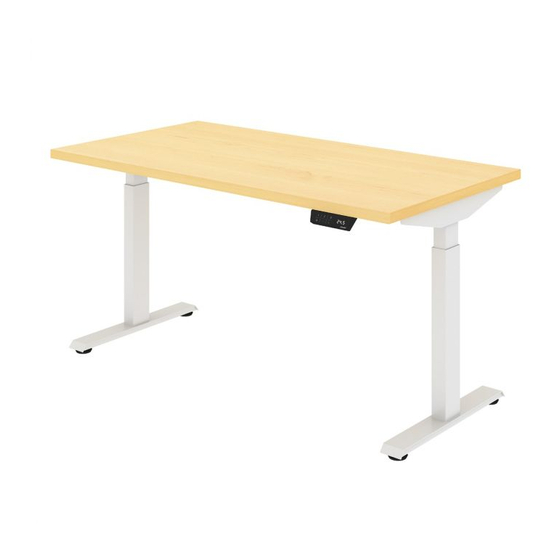
- Page 1 MY-HITE ADJUSTABLE TABLE Model Number : FSQAHT Please Read Instructions Before Use ASSEMBLY INSTRUCTIONS...
-
Page 2: Tools Needed
2. When moving My-Hite tables, please lift the tables, do not drag MANUAL»CAN»RESULT»IN»PRODUCT»DAMAGE,»OR»PERSONAL»INJURY. them. Friant & Associates, LLC does not assume any responsibility for product that is altered in any way. 3. Check that the load on the table does not exceed limits (220lbs straight, 330lbs corner). -
Page 3: Parts List
Parts List Installation Steps Step»1: Place worksurface finished PART# NAME PIECES side down on a blanket. Side Bracket Step»2: Insert A side bracket into B crossbeam assembly. WORKSURFACE Column Leg Repeat with other 2 side brackets. SIDE»BRACKET Crossbeam Center Rails CROSSBEAM Control Panel Control Box... - Page 4 Installation Steps Installation Steps Step»4: Use 4 socket button head bolts, M6*12mm to attach side bracket, column leg and crossbeam together as shown Step»6: Place all 3 leg assemblies on worksurface and insert D center in detail. rails into C crossbeams as shown. Hole on center rails should be Repeat with other 2 legs.
- Page 5 Installation Steps Installation Steps Step»7: Secure D center rails to C crossbeams with K 8 socket Step»10: Secure the E control panel button head bolt M6*12mm. in the desired location with M 2 truss head screws M5*20mm. TRUSS»HEAD» SCREWS» M5*20mm CONTROL»...
- Page 6 Installation Steps Installation Steps Step»11: Insert the F control box Step»13: Install the G telescopic cover in-between crossbeams. plates, leaving exit space for the electrical power cords, and secure Step»12: Connect E control panel to F control box to worksurface with M 8 truss head with H connector wires.
-
Page 7: First Time Use
To»Set»the»Lower-Limit»Position: FIRST TIME USE: Use the UP/DOWN buttons to move the base to the desired minimum height position. Press and hold the “S” button until the LED display flashes “S-“ once and let go of the Step»15: It is important to reset the button. - Page 8 ERROR CODES: MY-HITE One leg does not move or does not move at the same rate/height with the other Error»code Explanation Description leg(s). E01-E06 Power Current error The hand controller displays E01-E06, all • If the height difference between legs during adjusting process exceeds columns stop.
Need help?
Do you have a question about the FSQAHT and is the answer not in the manual?
Questions and answers