Omron NX1P2 series User Manual
Machine automation controller nx-series nx1p2 cpu unit
Hide thumbs
Also See for NX1P2 series:
- Hardware user manual (264 pages) ,
- User manual (424 pages) ,
- Startup manual (126 pages)

Related Manuals for Omron NX1P2 series


Summary of Contents for Omron NX1P2 series
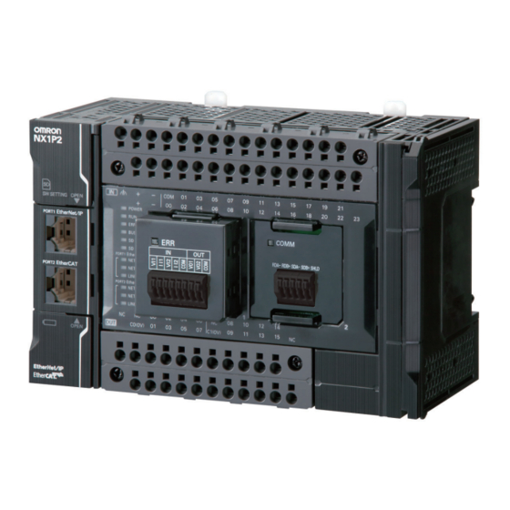
- Page 1 Machine Automation Controller NX-series NX1P2 CPU Unit Hardware User’s Manual NX1P2- NX1P2-1 CPU Unit W578-E1-02...
- Page 2 No patent liability is assumed with respect to the use of the information contained herein. Moreover, because OMRON is constantly striving to improve its high-quality products, the information contained in this manual is subject to change without notice. Every precaution has been taken in the preparation of this manual. Neverthe- less, OMRON assumes no responsibility for errors or omissions.
-
Page 3: Introduction
Introduction Introduction Thank you for purchasing an NX-series NX1P2 CPU Unit. This manual contains information that is necessary to use the NX-series NX1P2 CPU Unit. Please read this manual and make sure you understand the functionality and performance of the NX-series NX1P2 CPU Unit before you attempt to use it in a control system. -
Page 4: Table Of Contents
CONTENTS CONTENTS Introduction ......................1 Intended Audience............................1 Applicable Products ............................. 1 CONTENTS........................ 2 Relevant Manuals ..................... 6 Manual Structure ...................... 8 Page Structure ............................. 8 Special Information ............................9 Precaution on Terminology .......................... 9 Terms and Conditions Agreement ................ 10 Warranty, Limitations of Liability ........................ -
Page 5: Contents
CONTENTS Section 2 System Configuration Basic System Configuration....................2-2 2-1-1 EtherCAT Network Configuration....................2-3 2-1-2 NX Unit Configuration ......................... 2-4 Connecting to the Sysmac Studio ..................2-6 Network Configuration......................2-7 Section 3 Configuration Units CPU Units ..........................3-2 3-1-1 Models and Specifications ......................3-2 3-1-2 Part Names and Functions ...................... - Page 6 CONTENTS Section 5 Installation and Wiring Processing at Power ON and Power OFF ................5-3 5-1-1 Power ON Operation........................5-3 5-1-2 Power OFF Operation ......................... 5-4 5-1-3 Resetting the Controller from the Sysmac Studio ............... 5-6 Fail-safe Circuits........................5-7 Mounting Units........................5-9 5-3-1 Installation in a Control Panel ....................
- Page 7 CONTENTS 7-1-2 Periodic Inspections........................7-2 7-1-3 Unit Replacement Precautions ....................7-4 Replacing the Battery......................7-5 Appendices A-1 Specifications ........................A-2 A-2 Dimensions ..........................A-3 A-2-1 NX-series NX1P2 CPU Units...................... A-3 A-2-2 End Cover........................... A-4 A-2-3 SD Memory Card ........................A-4 A-2-4 Option Board..........................A-5 A-3 Version Information.......................A-6 A-3-1 Relationship between Unit Versions of CPU Units and Sysmac Studio Versions.......
-
Page 8: Relevant Manuals
Relevant Manuals Relevant Manuals The following table provides the relevant manuals for the NX-series CPU Units. Read all of the manuals that are relevant to your system configuration and application before you use the NX-series CPU Unit. Most operations are performed from the Sysmac Studio Automation Software. Refer to the Sysmac Stu- dio Version 1 Operation Manual (Cat. - Page 9 Relevant Manuals Manual Basic information Purpose of use Learning about error management and corrections Maintenance Using motion control Using EtherCAT Using EtherNet/IP Refer to the NJ/NX-series Troubleshooting Manual (Cat.
-
Page 10: Manual Structure
Manual Structure Manual Structure Page Structure The following page structure is used in this manual. Level 1 heading 4 Installation and Wiring Level 2 heading Level 3 heading Mounting Units Level 2 heading Gives the current Level 3 heading headings. 4-3-1 Connecting Controller Components The Units that make up an NJ-series Controller can be connected simply by pressing the Units together... -
Page 11: Special Information
Manual Structure Special Information Special information in this manual is classified as follows: Precautions for Safe Use Precautions on what to do and what not to do to ensure safe usage of the product. Precautions for Correct Use Precautions on what to do and what not to do to ensure proper operation and performance. Additional Information Additional information to read as required. -
Page 12: Terms And Conditions Agreement
Omron’s exclusive warranty is that the Products will be free from defects in materials and workman- ship for a period of twelve months from the date of sale by Omron (or such other period expressed in writing by Omron). Omron disclaims all other warranties, express or implied. -
Page 13: Application Considerations
Disclaimers Performance Data Data presented in Omron Company websites, catalogs and other materials is provided as a guide for the user in determining suitability and does not constitute a warranty. It may represent the result of Omron’s test conditions, and the user must correlate it to actual application requirements. Actual perfor- mance is subject to the Omron’s Warranty and Limitations of Liability. -
Page 14: Safety Precautions
Safety Precautions Safety Precautions Definition of Precautionary Information The following notation is used in this manual to provide precautions required to ensure safe usage of an NX-series Controller. The safety precautions that are provided are extremely important to safety. Always read and heed the information provided in all safety precautions. The following notation is used. -
Page 15: Warnings
Safety Precautions Warnings WARNING During Power Supply Do not touch any of the terminals or terminal blocks while the power is being supplied. Doing so may result in electric shock. Do not attempt to take any Unit apart. In particular, high-voltage parts are present in the Power Supply Unit while power is supplied or immediately after power is turned OFF. - Page 16 Safety Precautions If there is interference in remote I/O communications or if a major fault level error occurs, output status will depend on the products that are used. Confirm the operation that will occur when there is interference in communi- cations or a major fault level error, and implement safety measures.
- Page 17 Safety Precautions Downloading Always confirm safety at the destination before you transfer a user program, configuration data, setup data, or device variables from the Sysmac Studio. The devices or machines may perform unexpected operation regardless of the operating mode of the CPU Unit. Actual Operation Check the user program, data, and parameter settings for proper execution before you use them for actual operation.
-
Page 18: Cautions
Safety Precautions Cautions Caution Application Do not touch any Unit when power is being supplied or immediately after the power supply is turned OFF. Doing so may result in burn injury. Wiring Be sure that all terminal screws and cable connector screws are tightened to the torque specified in the relevant manuals. -
Page 19: Precautions For Safe Use
Precautions for Safe Use Precautions for Safe Use Transporting and Disassembly • Do not attempt to disassemble, repair, or modify any Units. Doing so may result in malfunction or fire. • Do not drop any Unit or subject it to abnormal vibration or shock. Doing so may result in Unit malfunc- tion or burning. - Page 20 Precautions for Safe Use • Do not write on the CPU Unit with ink within the restricted region that is shown in the following figure. Also do not get this area dirty. When the Unit is installed or removed, ink or dirt may adhere to the pins in the NX connector, which may result in malfunctions.
- Page 21 Precautions for Safe Use • Do not incline or twist the flat-blade screwdriver while it is in a release hole on a screwless clamping terminal block of CPU Unit. Doing so may damage the terminal block. Terminal Terminal block block •...
- Page 22 Precautions for Safe Use Actual Operation • If you change the fail-soft operation setting, the output status when the error occurs may also change. Confirm safety before you change the setting. • If you use fail-soft operation, write programming to determine whether Unit I/O data is valid. Without such programming, the user program cannot distinguish between Units for which I/O refreshing is continued and Units for which I/O refreshing is stopped.
- Page 23 Precautions for Safe Use • Always confirm safety at the connected equipment before you reset Controller errors with an event level of partial fault or higher for the EtherCAT Master Function Module. When the error is reset, all slaves that were in any state other than Operational state due to a Con- troller error with an event level of partial fault or higher (in which outputs are disabled) will go to Oper- ational state and the outputs will be enabled.
- Page 24 Precautions for Safe Use • All related EtherNet/IP nodes are reset when you transfer settings for the built-in EtherNet/IP port (including IP addresses and tag data links settings). The settings can only be enabled after the reset. Confirm that the system will not be adversely affected by resetting nodes before you transfer the set- tings.
- Page 25 Precautions for Safe Use Motion Control • Confirm the axis number carefully before you perform an MC Test Run. • The motor is stopped if communications are interrupted between the Sysmac Studio and the CPU Unit during an MC Test Run. Connect the communications cable between the computer and CPU Unit securely and confirm that the system will not be adversely affected before you perform an MC Test Run.
- Page 26 Precautions for Safe Use Restoring Data • You cannot back up, restore, or compare some or all of the settings for certain slaves and Units. Also, you cannot back up, restore, or compare data for disabled slaves or Units. After you restore data, suf- ficiently confirm that operation is correct before you start actual operation.
- Page 27 Precautions for Safe Use Disposal • Dispose of the Units and Batteries according to local ordinances as they apply. • The following information must be displayed for all products that contain primary lithium batteries with a perchlorate content of 6 ppb or higher when shipped to or transported through the State of California, USA. Perchlorate Material - special handling may apply.
-
Page 28: Precautions For Correct Use
Precautions for Correct Use Precautions for Correct Use Storage and Installation • Follow the instructions in this manual to correctly perform installation. • Do not operate or store the Controller in the following locations. Doing so may result in burning, in operation stopping, or in malfunction. - Page 29 Precautions for Correct Use • For EtherCAT and EtherNet/IP, use the connection methods and cables that are specified in the NJ/NX-series CPU Unit Built-in EtherCAT Port User’s Manual (Cat. No. W505) and the NJ/NX-series CPU Unit Built-in EtherNet/IP Port User’s Manual (Cat. No. W506). Otherwise, communications may be faulty.
- Page 30 If there is a corrupted file in the SD Memory Card, the file is automatically deleted by the restoration function when the power supply is turned ON. • If you use an OMRON SD Memory Card, the end of the life of the SD Memory Card can be detected in the following ways.
- Page 31 Precautions for Correct Use Online Editing • When performing online editing, the CPU Unit saves a program updated by the online editing to built-in non-volatile memory. Sysmac Studio shows a message that it is in a backup operation. Do not turn OFF the power supply to the Controller while this message is displayed.
-
Page 32: Regulations And Standards
Concepts EMC Directives OMRON devices that comply with EU Directives also conform to the related EMC standards so that they can be more easily built into other devices or the overall machine. The actual products have been checked for conformity to EMC standards. -
Page 33: Conformance To Ul And Csa Standards
Sellers and/or users need to take note of this. Software Licenses and Copyrights This product incorporates certain third party software. The license and copyright information associated with this software is available at http://www.fa.omron.co.jp/nj_info_e/. NX-series NX1P2 CPU Unit Hardware User’s Manual (W578) -
Page 34: Versions
Versions Versions Hardware revisions and unit versions are used to manage the hardware and software in NX-series Units and EtherCAT slaves. The hardware revision or unit version is updated each time there is a change in hardware or software specifications. Even when two Units or EtherCAT slaves have the same model number, they will have functional or performance differences if they have different hardware revisions or unit versions. - Page 35 Versions Click the Show Detail or Show Outline Button at the lower right of the Production Information Dialog Box. The view will change between the production information details and outline. Outline View Detail View The information that is displayed is different for the Outline View and Detail View. The Detail View displays the unit version, hardware version, and software versions.
-
Page 36: Unit Versions Of Cpu Units And Sysmac Studio Versions
Versions Unit Versions of CPU Units and Sysmac Studio Versions The functions that are supported depend on the unit version of the NX-series CPU Unit. The version of Sysmac Studio that supports the functions that were added for an upgrade is also required to use those functions. -
Page 37: Related Manuals
Related Manuals Related Manuals The following manuals are related. Use these manuals for reference. Manual name Cat. No. Model numbers Application Description NX-series NX1P2 W578 NX1P2- Learning the basic An introduction to the entire NX1P2 CPU Unit Hardware specifications of CPU Unit system is provided along User’s Manual the NX-series... - Page 38 Related Manuals Manual name Cat. No. Model numbers Application Description NJ/NX-series W508 NX701- Learning about the The motion control instructions are Motion Control Instruc- specifications of described. NJ501- tions Reference Manual the motion control NJ301- instructions. NJ101- NX1P2- NJ/NX-series W505 NX701-...
- Page 39 Related Manuals Manual name Cat. No. Model numbers Application Description NX-series W521 NX-ID Learning how to Describe the hardware, setup meth- NX Units use NX Units. ods, and functions of the NX Units. NX-IA User’s Manuals Manuals are available for the follow- NX-OC...
-
Page 40: Terminology
Terminology Terminology Term Description absolute encoder home offsets This data is used to restore in the CPU Unit the actual position of a Servo Drive with an absolute encoder. The offset is the difference between the command position after homing and the absolute data that is read from the absolute encoder. array specification One of the variable specifications. - Page 41 Terminology Term Description CPU Unit The Unit that serves as the center of control for a Machine Automation Controller. The CPU Unit executes tasks, refreshes I/O for other Units and slaves, etc. The NJ/NX-series CPU Units include NX701-, NJ501-, NJ301-, NX1P2-.
- Page 42 ST programming that is included within a ladder diagram program. instruction The smallest unit of the processing elements that are provided by OMRON for use in POU algorithms. There are ladder diagram instructions (program inputs and out- puts), function instructions, function block instructions, and ST statements.
- Page 43 Terminology Term Description PDO communications An abbreviation for process data communications. Data is exchanged between the master and slaves on a process data communications cycle. (The process data com- munications cycle is the same as the task period of the primary periodic task.) periodic task A task for which user program execution and I/O refreshing are performed each period.
- Page 44 Terminology Term Description union One of the derivative data types. It allows you to handle the same data as different data types. Unit A device that mounts to the CPU Rack or an Expansion Rack. Unit configuration The configuration information for the Units that are set on the Sysmac Studio. This information tells what Unit models are connected to the CPU Unit and where they are connected.
-
Page 45: Revision History
Revision History Revision History A manual revision code appears as a suffix to the catalog number on the front and back covers of the manual. W578-E1-02 Cat. No. Revision code Revision Date Revised content code October 2016 Original production April 2017 Made changes accompanying release of unit version 1.14 of the CPU Unit. - Page 46 Revision History NX-series NX1P2 CPU Unit Hardware User’s Manual (W578)
-
Page 47: Sections In This Manual
Sections in this Manual Sections in this Manual Introduction to NX-series Controllers System Configuration Configuration Units Designing the Power Supply System Installation and Wiring Troubleshooting Inspection and Maintenance Appendices Index NX-series NX1P2 CPU Unit Hardware User’s Manual (W578) - Page 48 Sections in this Manual NX-series NX1P2 CPU Unit Hardware User’s Manual (W578)
-
Page 49: Introduction To Nx-Series Controllers
Introduction to NX-series Controllers This section describes the features, basic system configuration, specifications, and overall operating procedure of an NX-series NX1P2 Controller. 1-1 The NX-series Controllers ........1-2 1-1-1 Features . -
Page 50: The Nx-Series Controllers
They provide the safety, reliability, and maintainability that are required of industrial controllers. The NX-series Controllers provide the functionality of previous OMRON PLCs, and they also provide the functionality that is required for motion control. Especially, the NX-series NX1P2 Controller can perform I/O operation with an attached NX Unit or Option Board, and with the built-in I/O. - Page 51 1 Introduction to NX-series Controllers Support for EtherCAT Slave Terminals You can use EtherCAT Slave Terminals to save space. You can also flexibly build systems with the wide variety of NX Units. Achieving a Safety Subsystem on EtherCAT You can use NX-series Safety Control Units to integrate safety controls in a sequence and motion control system as a subsystem on EtherCAT.
- Page 52 Programming Languages Based on the IEC 61131-3 International Standard The NX-series Controllers support language specifications that are based on IEC 61131-3. To these, OMRON has added our own improvements. Motion control instructions that are based on PLCo- ® standards and an instruction set (POUs) that follows IEC rules are provided.
-
Page 53: Introduction To The System Configurations
1 Introduction to NX-series Controllers 1-1-2 Introduction to the System Configurations The NX-series NX1P2 Controller supports the following system configurations. Basic System Configurations The NX-series NX1P2 Controller basic configurations include the EtherCAT network configuration, NX unit configuration, and the Support Software. •... - Page 54 CPU Unit Interface Unit Option Board Built-in EtherCAT Serial communications port devices CompoNet Master Unit DeviceNet Unit Serial Communications Unit General-purpose components or OMRON components Field Level EtherCAT RS-232C, RS-422A/485 General-purpose Serial slaves EtherCAT Vision communications Servo Drives Slave Terminal...
- Page 55 1 Introduction to NX-series Controllers Support Software You can use the following Support Software to set up, monitor, and debug an NX-series Controller. • Sysmac Studio The Sysmac Studio is the main Support Software that you use for an NX-series Controller. On it, you can set up the Controller configurations, parameters, and programs, and you can debug and simulate operation.
- Page 56 1 Introduction to NX-series Controllers Specifications This section gives the main specifications of the NX-series NX1P2 CPU Units. NX1P2- Item 11/ 10/ 90/ 111 101 901 LD instruction 3.3 ns Process- Instruction exe- Math instructions (for long real 70 ns or more ing time cution times data)
- Page 57 1 Introduction to NX-series Controllers NX1P2- Item 11/ 10/ 90/ 111 101 901 Number of ports Physical layer 10BASE-T, 100BASE-TX Frame length 1,514 bytes max. Media access method CSMA/CD Modulation Baseband Topology Star Baud rate 100 Mbps/s (100BASE-TX) STP (shielded, twisted-pair) cable of Ethernet cate- Transmission media gory 5, 5e or higher Maximum transmission distance between Ethernet...
- Page 58 1 Introduction to NX-series Controllers NX1P2- Item 11/ 10/ 90/ 111 101 901 Communications standard IEC 61158 Type12 EtherCAT master specifications Class B (Feature Pack Motion Control compliant) Physical layer 100BASE-TX Modulation Baseband Baud rate 100 Mbps (100BASE-TX) Duplex mode Auto Topology Line, daisy chain, and branching...
- Page 59 1 Introduction to NX-series Controllers *2. Memory used for CJ-series Units is included. *3. The value can be set in 1 ch increments. The value is included in the total size of variables without a Retain attribute. *4. The value can be set in 1 ch increments. The value is included in the total size of variables with a Retain attribute. *5.
-
Page 60: Overall Operating Procedure For The Cpu Unit
1 Introduction to NX-series Controllers Overall Operating Procedure for the CPU Unit This section gives the overall operating procedure of the NX1P2 CPU Unit Controllers and then describes it in more detail. 1-3-1 Overall Procedure The overall procedure to use an NX1P2 CPU Unit Controller is given below. Step . -
Page 61: Procedure Details
1 Introduction to NX-series Controllers 1-3-2 Procedure Details Step 1. Software Design Step Description Reference Step 1-1 • External I/O devices and unit configuration NJ/NX-series CPU Unit Soft- Designing I/O and Pro- ware User’s Manual (Cat. No. • Refresh periods for external devices cessing W501) •... - Page 62 1 Introduction to NX-series Controllers Registering device variables in variable I/O Map NJ/NX-series CPU Unit Soft- table ware User’s Manual (Cat. No. 2) Assigning Device (Variable names are user defined or auto- W501) Variables to I/O Ports matically created.) (The following step is for motion control.) Creating the axes and setting them as real Configurations NJ/NX-series CPU Unit Soft-...
- Page 63 1 Introduction to NX-series Controllers Step 2-3 Programming Global Variable Sysmac Studio Version 1 • Registering the variables used by more 1) Registering Vari- than one POU in the global variable Table Editor Operation Manual (Cat. No. ables table with Sysmac Studio W504) Local Variable •...
- Page 64 1 Introduction to NX-series Controllers • Wiring the built-in I/O 5-4-9 Wiring the Built-in I/O 3) Wiring I/O on page 5-58 • Wiring I/O for NX Units Manuals for the specific NX • Connecting an Option Board Units 5-4-10 Wiring the NX1W-CIF01 Serial Commu- nications Option Board on page 5-62...
- Page 65 System Configuration This section describes the basic system configuration used for NX-series NX1P2 Con- trollers. 2-1 Basic System Configuration ........2-2 2-1-1 EtherCAT Network Configuration .
-
Page 66: System Configuration
2 System Configuration Basic System Configuration An NX-series NX1P2 Controller supports the following two types of configurations. • Basic Configuration The basic configurations include the CPU Unit and the Configuration Units that are controlled directly by the CPU Unit. There are two basic configurations. a) EtherCAT network configuration b) NX Unit configuration •... -
Page 67: Ethercat Network Configuration
2 System Configuration 2-1-1 EtherCAT Network Configuration The EtherCAT network configuration consists of an NX-series NX1P2 CPU Unit, an End Cover, and the EtherCAT slaves. You use the built-in EtherCAT port on the NX-series NX1P2 CPU Unit to connect EtherCAT slaves. NX-series NX1P2 CPU Unit CPU Rack End Cover... -
Page 68: Nx Unit Configuration
NX Units. Unit Load Cell Input Unit For information on the most recent lineup of NX Units, refer to NX-series catalogs or OMRON websites, or ask your OMRON representative. Option Board Serial Communications One or two Option Boards can be Option Board connected to the CPU Unit. - Page 69 2 System Configuration Configuration Units NX-series NX1P2 CPU Units The Unit that serves as the center of control for a Machine Automation Controller. It executes tasks, refreshes I/O for other Units and slaves, etc. In the NX-series, this type of Units are called NX1P2 CPU Units.
-
Page 70: Connecting To The Sysmac Studio
2 System Configuration Connecting to the Sysmac Studio Connect the NX-series NX1P2 CPU Unit and the Sysmac Studio through EtherNet/IP. Refer to 3-7-2 Connection on page 3-34 for information on how to make the connection between the NX-series NX1P2 CPU Unit and the Sysmac Studio. 2 - 6 NX-series NX1P2 CPU Unit Hardware User’s Manual (W578) -
Page 71: Network Configuration
CPU Unit Interface Unit Option Board Built-in EtherCAT Serial communications port devices CompoNet Master Unit DeviceNet Unit Serial Communications Unit General-purpose components or OMRON components Field Level EtherCAT RS-232C, RS-422A/485 General-purpose Serial slaves EtherCAT Vision communications Servo Drives Slave Terminal... - Page 72 2 System Configuration Connection Connection method Sysmac Studio Use USB or the built-in EtherNet/IP port. For NX1P2 CPU Units, only the built-in EtherNet/IP port can be used. Between Control- NJ/NX-series Controller or CJ-series Use the built-in EtherNet/IP port or a port on an Eth- lers erNet/IP Unit.
- Page 73 Configuration Units This section describes configuration devices in the NX-series NX1P2 Controller config- uration. 3-1 CPU Units ........... . 3-2 3-1-1 Models and Specifications .
-
Page 74: Cpu Units
3 Configuration Units CPU Units This section describes the models and specifications of the CPU Units as well as the names and func- tions of the parts. 3-1-1 Models and Specifications This section describes the outline of the CPU Unit specifications. The electrical and mechanical specifications of the CPU Unit are also given. - Page 75 3 Configuration Units Electrical and Mechanical Specifications The electrical and mechanical specifications are given below. Item Specification Model NX1P2-140DT NX1P2-9024DT Enclosure Mounted in a panel 154 × 100 × 71 mm (W×H×D) 130 × 100 × 71 mm (W×H×D) Dimensions (mm) NX1P2-140DT: 650 g NX1P2-9024DT: 590 g Weight...
-
Page 76: Part Names And Functions
3 Configuration Units 3-1-2 Part Names and Functions The following two models have the different numbers of the option board slots and built-in I/O points, but the names and functions of their parts are the same. Refer to 3-1-1 Models and Specifications on page 3-2 for the CPU Unit models and specifications such as the number of built-in I/O points. - Page 77 3 Configuration Units Letter Name Function Unit hookup guides These guides are used to mount an NX Unit or End Cover. NX bus connector This connector is used to connect the CPU Unit to the NX Unit on the right of the CPU Unit. Option board slot 1 (left), Remove the covers of the slots and mount Option Boards.
-
Page 78: Operation Status Indicators
3 Configuration Units 3-1-3 Operation Status Indicators CPU Unit Operation Status Indicators There are the indicators to show the operation status of Unit in the center of the front side of the CPU Unit. CPU Unit Status indicator Built-in EtherNet/IP Status indicator Built-in EtherCAT Status indicator... - Page 79 3 Configuration Units Indicator Color Status Meaning Green Lit. The CPU Unit is in normal operation in RUN mode. (The user pro- gram is in execution.) Flashing The CPU Unit is starting (entering RUN mode or PROGRAM at 2-s mode at startup). intervals, then flashing at 0.5-s...
- Page 80 3 Configuration Units Precautions for Safe Use • Do not turn OFF the power supply to the Controller while the BUSY indicator flashes. While the BUSY indicator is lit, the user program and settings in the CPU Unit are being backed up in the built-in non-volatile memory.
- Page 81 3 Configuration Units Built-in EtherCAT (Port 2) Status Indicators These indicators show the operation status of the built-in EtherCAT port of the CPU Unit. Indicator Color Status Meaning NET RUN Green Lit. EtherCAT communications are in progress. • Inputs and outputs for I/O data are in operation. Flashing EtherCAT communications are established.
-
Page 82: Terminal Blocks
3 Configuration Units 3-1-4 Terminal Blocks The terminal blocks on the CPU Unit are removable screwless clamping terminal blocks that allow you to easily connect and remove the wiring. There are the input terminal block and output terminal block. This section provides the part names and functions of the terminal blocks, the terminal arrangement of the input and output terminal blocks, and other information. - Page 83 3 Configuration Units Input Terminal Block Terminal Arrangement The description is given for each CPU Unit model. a) NX1P2-140DT Symbol Terminal name Description Reference Functional ground termi- The functional ground terminal. Con- 5-4-5 Grounding on page nect the ground wire to the terminal. 5-41 Unit power supply termi- These terminals are connected to the...
- Page 84 3 Configuration Units Input Specifications The specifications depends on the input terminal numbers of the model. Item Specification Input type General-purpose input A General-purpose input B NX1P2-140DT: 00 to 15 NX1P2-140DT: 16 to 23 Input terminal number NX1P2-9024DT: 00 to 13 NX1P2-9024DT: None Internal I/O common For both NPN/PNP...
- Page 85 3 Configuration Units Output Terminal Block Terminal Arrangement The description is given for each CPU Unit model. a) NX1P2-140DT (0V) (0V) Symbol Terminal name Description Reference C0 (0V), Common terminal Connected to the 0-V side of the I/O Output Specifications on page C1 (0V) power supply.
- Page 86 3 Configuration Units c) NX1P2-9024DT The appearance of the terminal block is the same as a). (0V) Symbol Terminal name Description Reference C0 (0V) Common terminal Connected to the 0-V side of the I/O Output Specifications on page power supply. 3-15 00 to 09 Output terminals...
- Page 87 3 Configuration Units Output Specifications The models of the CPU Units are divided according to the following two output types: the NPN (sink- ing) type and PNP (sourcing) type. There is no difference in specifications between the models with different output terminal numbers. Specification Item NX1P2-DT...
-
Page 88: Battery
3 Configuration Units 3-1-5 Battery The battery is not mounted when the product is shipped. To turn OFF the power supply to the equipment for a certain period of time by using the clock data for programming, event logs, etc., you need a separately-sold battery to retain the clock data. The following describes the purpose of the battery mounting, the battery model, and the battery-related error detection and clock data settings. - Page 89 3 Configuration Units Battery-related Error Detection and Clock Data Settings Because the CPU Unit is shipped with the battery not mounted, the Battery-related error detection is set to Do not use by default. The behavior of the CPU Unit when a battery-related error is detected depends on whether battery error detection is used or not used as shown in the table below.
-
Page 90: Id Information Indication
Shows the lot number and the serial number of the CPU Unit. number DDMYY: Lot number, : For use by OMRON, SSSS: Serial number M is 1 to 9 for January to September, X for October, Y for November, and Z for December. -
Page 91: Sd Memory Cards
This section describes the models, specifications, and application of the SD Memory Cards. 3-2-1 Models and Specifications SD cards and SDHC cards are supported, but use one of the following OMRON Cards. OMRON is not responsible for the operation, performance, or write life of any other SD or SDHC card. Capacity... -
Page 92: Serial Communications Option Board
3 Configuration Units Serial Communications Option Board 3-3-1 Models and Specifications NX-series NX1P2 CPU Unit COMM COMM RDA- RDB+ SDA- SDB+ SHLD SG0 RD SDER SG1 DR RS CS SHLD RS-232C RS-422A/485 Option Board Option Board (NX1W-CIF01) (NX1W-CIF11/12) This section explains the specifications that are common to all types of Serial Communications Option Boards. -
Page 93: Purpose
3 Configuration Units Item Specification Model NX1W-CIF01 NX1W-CIF11 NX1W-CIF12 One RS-232C port One RS-422A/485 port One RS-422A/485 port (iso- Communications port lated) Communications Half-duplex method Synchronization method Start-stop synchronization Baud rate 1.2/2.4/4.8/9.6/19.2/38.4/57.6/115.2 kbps Transmission distance 15 m 50 m 500 m Supported protocol Host link, Modbus-RTU master, and no-protocol Screwless clamping terminal... -
Page 94: Part Names And Functions
3 Configuration Units 3-3-3 Part Names and Functions RS-232C Option Board (NX1W-CIF01) Communications status indicator COMM SG0 RD SDER SG1 DR RS CS SHLD RS232C terminal block Communications Status Indicator Indicator Color Status Description COMM Yellow Lit. Communications are being performed. Not lit. - Page 95 3 Configuration Units RS-422A/485 Option Board (NX1W-CIF11/NX1W-CIF12) Front Back (CIF11) Back (CIF12) Communications status indicator CPU Unit connector COMM RDA- RDB+ SDA- SDB+ SHLD SW 1 SW 2 SW 1 Operation setting DIP switch (SW2) RS-422A/485 terminal Operation setting DIP Operation setting DIP block switch (SW1)
- Page 96 3 Configuration Units CIF11 CIF12 Setting Terminating Select whether a terminating resistance resistance pro- is provided or not. The value of a termi- vided nating resistance is approximately 220 Ω. Terminating resistance not provided Two-wire type Select the two-wire or four-wire type. Four-wire type To set the two-wire type, turn ON both Two-wire type...
-
Page 97: Analog I/O Option Board
3 Configuration Units Analog I/O Option Board 3-4-1 Models and Specifications NX-series NX1P2 CPU Unit Analog Input Analog Output Analog I/O Option Board Option Board Option Board (NX1W-ADB21) (NX1W-DAB21V) (NX1W-MAB221) This section explains the specifications that are common to all types of Analog I/O Option Board. Refer to 3-4-3 Part Names and Functions on page 3-27 for details. -
Page 98: Purpose
3 Configuration Units Item Specification Model NX1W-ADB21 NX1W-DAB21V NX1W-MAB221 Analog input Analog output Analog I/O Voltage input 0 to 10 V 2 words total 0 to 10 V 2 words total Current input 0 to 20 mA 0 to 20 mA Voltage output 0 to 10 V 2 words... -
Page 99: Part Names And Functions
3 Configuration Units 3-4-3 Part Names and Functions Analog Input Option Board (NX1W-ADB21) Status indicator Analog input terminal block Status Indicator Indicator Color Status Description Lit. An Option Board Error (WDT) was detected by the self-diagnostic function. Flashing. A Communications Error occurred between the Option Board and the CPU Unit. - Page 100 3 Configuration Units Analog Input Specifications Specification Item Voltage input Current input Input method Single-ended input Single-ended input Input range 0 to 10 V 0 to 20 mA Input conversion range 0 to 10.24 V 0 to 30 mA Absolute maximum rating -1 to 15 V -4 to 30 mA...
- Page 101 3 Configuration Units Analog Output Specifications Specification Item Voltage output Current output Output range 0 to 10 V Output conversion range 0 to 10.24 V Allowable load resistance 2 kΩ min. Output impedance 0.5 Ω max. Resolution 1/4,000 (full scale: 4,000) 25°C ±0.5% (full scale) Overall accu-...
- Page 102 3 Configuration Units Analog I/O Terminal Array Abbreviation Signal name Voltage output 1 Current input 1 Voltage input 2 Current input 2 Input common Voltage output 1 Voltage output 2 Output common Precautions for Correct Use When you use the current input, be sure to short-circuit V I1 with I I1, and short-circuit V I2 with I I2.
-
Page 103: Power Supply-Related Units
3 Configuration Units Power Supply-related Units The following NX Units are the NX-series power supply-related Units. When configuring NX Units, you can use these Units as necessary to supply power to the NX Units. These NX Units are collectively called as the System Units. •... -
Page 104: Nx Units
(D) (E) Symbol Name Function Marker attachment loca- The locations where markers are attached. OMRON markers are tion pre-installed at the factory. You can also install commercially available markers. NX bus connector This connector is used to connect another Unit. -
Page 105: Sysmac Studio
3 Configuration Units Sysmac Studio The Sysmac Studio is a Support Software package that provides an integrated development environ- ment to design, program, debug, and maintain SYSMAC NJ/NX-series Controllers. This section describes the models and connecting methods of the Sysmac Studio. 3-7-1 Model Numbers The model numbers of the Sysmac Studio are given in the following table. -
Page 106: Connection
3 Configuration Units 3-7-2 Connection With an NX1P2 CPU Unit, you can connect the Sysmac Studio online in the following ways. Configuration Connection with EtherNet/IP • 1:1 Connection • 1:N Connection Sysmac Studio Sysmac Studio EtherNet/IP EtherNet/IP • A direct connection is made from the Directly specify the IP address of the remote device. - Page 107 3 Configuration Units Additional Information The Sysmac Studio cannot connect online to an NJ/NX-series CPU Unit in the following type of configuration. • If the built-in EtherNet/IP port is not used, you cannot connect to an NJ/NX-series CPU Unit on an EtherNet/IP network. Example: Connection to NJ/NX-series CPU Unit Routing through an EtherNet/IP Unit or Built-in Port Sysmac Studio...
- Page 108 3 Configuration Units 3 - 36 NX-series NX1P2 CPU Unit Hardware User’s Manual (W578)
-
Page 109: Designing The Power Supply System
Designing the Power Supply Sys- This section describes how to design the power supply system for the NX-series NX1P2 CPU Unit. 4-1 Power Supply System and Design Concepts ..... . . 4-2 4-1-1 Power Supply System and Types of Power Supplies . -
Page 110: Power Supply System And Design Concepts
4 Designing the Power Supply System Power Supply System and Design Concepts This section describes the power supply system for the CPU Rack of an NX-series NX1P2 CPU Unit and the design concepts. 4-1-1 Power Supply System and Types of Power Supplies Power Supply System Configuration Diagram An example of a power supply system configuration diagram for the CPU Rack of an NX1P2 CPU Unit is shown below. - Page 111 4 Designing the Power Supply System Power Supply Types There are the following two types of power supplies that supply power to the CPU Rack of an NX1P2 CPU Unit. Power supply type Description Unit power supply This is the power supply for generating the internal power supply required for the CPU Rack to operate.
-
Page 112: Nx-Series Power Supply-Related Units
User’s Manual (Cat. No. W523). For information on the most recent lineup of NX Series power sup- ply-related Units, refer to NX-series catalogs or OMRON websites, or ask your OMRON representative. The feature and purpose of each Unit in the NX Unit configuration with an NX-series NX1P2 CPU Unit are given below. - Page 113 4 Designing the Power Supply System Unit name Function Additional This NX Unit provides additional I/O power supply. I/O Power This Unit is used when the type of the I/O power supply to NX Units connected to the CPU Unit is Supply Unit the supply from NX bus.
-
Page 114: Design Concepts For Power Supply To The Cpu Rack
4 Designing the Power Supply System Unit name Function I/O Power This NX Unit is used when there are not enough I/O power supply terminals for the connected Supply external devices that are connected to NX Units such as Digital I/O Units and Analog I/O Units. Connection Unit power supply terminals Unit... -
Page 115: Designing The Nx Unit Power Supply System
4 Designing the Power Supply System Designing the NX Unit Power Supply System This section describes how to design the NX Unit power supply to the CPU Rack of the NX-series NX1P2 CPU Unit. 4-2-1 Procedure for Designing the NX Unit Power Supply System The total power consumption from the NX Unit power supply must not exceed the NX Unit power supply capacity of the Unit that supplies the NX Unit power. -
Page 116: Calculation Example For The Nx Unit Power Supply
4 Designing the Power Supply System NX Unit Power Supply Capacity and Restrictions The internal power supply circuits of the CPU Unit or Additional NX Unit Power Supply Unit supply the NX Unit power to the NX Units. The NX Unit power supply capacity does not include the NX Unit power consumption of the Addi- tional NX Unit Power Supply Units. - Page 117 4 Designing the Power Supply System Additional Information Excess or insufficiency in the NX Unit power supply capacity can be easily checked when the Unit configuration is created on the CPU and Expansion Racks Tab Page on the Sysmac Stu- dio.
-
Page 118: Designing The I/O Power Supply System
4 Designing the Power Supply System Designing the I/O Power Supply Sys- This section describes how to design the I/O power supply to the NX Units connected to the NX-series NX1P2 CPU Unit. 4-3-1 I/O Power Supply Method There are the following three methods to supply the I/O power supply to the NX Units depending on the type and model of the NX Units. -
Page 119: Designing The I/O Power Supply From The Nx Bus
4 Designing the Power Supply System 4-3-2 Designing the I/O Power Supply from the NX Bus Procedure for Designing the I/O Power Supply The procedure is explained under the precondition that an Additional I/O Power Supply Unit is connected to the right side of the CPU Unit because an NX Unit that require the power supply from NX bus is mounted on the CPU Rack. - Page 120 4 Designing the Power Supply System 8 max. a. Total current consumption from I/O power a. Total current consumption from I/O power supply is 4 A or less supply is 4 A or less (NX Units with the supply from external (NX Units with the supply from external source or no supply are excluded from source or no supply are excluded from...
- Page 121 4 Designing the Power Supply System Calculating the Total Current Consumption from the I/O Power Sup- The total current consumption from the I/O power supply from the NX bus is the total of the following current consumptions. • The current consumption from the I/O power supply that is required for the Additional I/O Power Sup- ply Unit and for the NX Units that are connected to the Additional I/O Power Supply Unit •...
- Page 122 4 Designing the Power Supply System (a) Unit Specifications Model Current consumption from I/O power supply Input current NX-PF0730 10 mA NX-ID3317 0 mA 6 mA/point NX-OD3121 10 mA (b) Calculations The current consumption from the I/O power supply for each Unit is calculated as follows. NX-PF0730 Current Consumption = Current consumption from I/O power supply = 10 mA...
- Page 123 4 Designing the Power Supply System Calculating the Voltage Drop in the I/O Power Supply Voltage drop occurs in the CPU Units and NX Units due to the contact resistance at the points where Units are connected to each other. Design the I/O power supply system to maintain the voltage specifi- cations of the NX Unit I/O circuits and connected external devices even if the voltage of the I/O power supply drops.
-
Page 124: Designing The I/O Power Supply From External Sources
4 Designing the Power Supply System Procedure Use the following formula to calculate the total current consumption from the I/O power supply. Total current consumption from the I/O power supply =(1) + (2) + (3) + (4) + (5) = 0.0 A + 0.5 A + 0.5 A + 0.0 A + 2.0 A = 3 A Find the I/O power supply voltage and make sure that it is within the voltage specifications of the... -
Page 125: Restrictions On Inrush Current For On/Off Operation
4 Designing the Power Supply System 4-3-5 Restrictions on Inrush Current for ON/OFF Operation This section describes the restrictions on inrush current from the I/O power supply that occurs when connected external devices turn ON and OFF. Inrush Current Restrictions If inrush current to the I/O power supply occurs when a connected external device turns ON or OFF, do not allow the effective value of the I/O power supply current to exceed the following rated values when the inrush current is added to the current consumption from the I/O power supply. -
Page 126: Selecting External Power Supplies And Protective Devices
• Has double or reinforced insulation between the input and output. • Has an output voltage of 24 VDC (20.4 to 28.8 VDC). Recommended Power Supplies: S8VK-S Series (manufactured by OMRON) Calculating the Required Power Supply Capacity of the Unit Power Supply ... - Page 127 4 Designing the Power Supply System Blocks A block consists of the Unit that supplies the NX Unit power and the range of Units to which that Unit supplies the NX Unit power. For example, in the configuration in the following figure there are two blocks in the CPU Rack: the block with the CPU Unit and the block with the Additional NX Unit Power Supply Unit.
-
Page 128: Selecting The I/O Power Supplies
*1. Use an output voltage that is appropriate for the I/O circuits of the NX Units and the connected external devices. Recommended Power Supplies: S8VK-S Series (manufactured by OMRON) Calculating the Required Power Supply Capacity of the I/O Power Supply for NX Units... -
Page 129: Selecting Protective Devices
4 Designing the Power Supply System 4-4-3 Selecting Protective Devices This section describes how to select protective devices (e.g., breakers and fuses) to protect against short circuits and overcurrents in external circuits. Overcurrent is the current that flows when an excessive load is connected and one of the following rat- ings is exceeded. - Page 130 4 Designing the Power Supply System For I/O Power Supply Current Breaking/fusing time 1 min max. 12 A 15 s max. 21 A 5 s max. 30 A 2.5 s max. Installation Locations for Protective Devices Install protective devices for the Unit power supply and I/O power supply in the locations that are shown in the following figure.
- Page 131 4 Designing the Power Supply System • Using Unwired Unit Power Supply Terminals In this example, the current consumption from each power supply is as follows: Current consumption from Unit power supply: I_unit1 + I_unit2 ≤ Lowest rated current Current consumption from I/O power supply for NX Units: I_io1 + I_io2 ≥ 4 A (rated current for I/O power supply) Block that an Additional NX Unit Power Supply Block that the CPU Unit supplies Unit power supply.
- Page 132 4 Designing the Power Supply System • When Total Current Consumption for All Blocks Does Not Exceed the Rated Current In this example, the current consumption from each power supply is as follows: Current consumption from Unit power supply: I_unit1 + I_unit2 ≤ Lowest rated current Current consumption from I/O power supply for NX Units: I_io1+I_io2 ≤...
- Page 133 Installation and Wiring This section describes how to install and wire the NX-series NX1P2 CPU Unit as well as details on installation locations. 5-1 Processing at Power ON and Power OFF ......5-3 5-1-1 Power ON Operation .
- Page 134 5 Installation and Wiring 5-5 Control Panel Installation ........5-74 5-5-1 Temperature .
-
Page 135: Processing At Power On And Power Off
5 Installation and Wiring Processing at Power ON and Power WARNING • Do not touch the terminal section while power is ON. Electrical shock may occur. • Do not disassemble any of the Units. Particularly the Units contain parts with high voltages when power is ON or immediately after power is turned OFF. -
Page 136: Power Off Operation
5 Installation and Wiring *1. Refer to 6-1-2 Fatal Errors in the CPU Unit on page 6-3 for information on the Power Supply Error, CPU Unit Reset, Hardware Initialization Error, and System Initialization Error. Operating Mode at Startup The system will immediately enter RUN mode if RUN mode (default) is set as the startup operating mode. - Page 137 5 Installation and Wiring Operation at Power OFF Execution of the user program is ended if a power interruption exceeds the time shown in the table below. The processing after power interruption confirmation (described below) is performed, and then the system (i.e., CPU Unit) stops. System stops.
-
Page 138: Resetting The Controller From The Sysmac Studio
5 Installation and Wiring Processing After Power Interruption Is Confirmed After a power interruption is confirmed, the CPU Unit performs the following processing and then stops. Item Description I/O refresh I/O refresh stops, and all outputs are turned OFF. Tag data links via the EtherNet/IP stop. -
Page 139: Fail-Safe Circuits
5 Installation and Wiring Fail-safe Circuits WARNING Provide safety measures in external circuits to ensure safety in the system if an abnormality occurs due to malfunction of the CPU Unit, slaves, or Units or due to other external factors affecting oper- ation. - Page 140 5 Installation and Wiring Order of Powering On the Controller and Controlled System Outputs from Units, such as DC Output Units, may malfunction momentarily when the Unit power supply is turned ON. This may cause problems in the system if the Unit power supply is turned ON after the I/O power supply (i.e.
-
Page 141: Mounting Units
5 Installation and Wiring Mounting Units This section describes how to mount Units to the NX-series Controller. Precautions for Safe Use Always turn OFF the power supply to the Controller before attempting any of the following. • Mounting or removing NX Units or CPU Units •... -
Page 142: Installation In A Control Panel
5 Installation and Wiring 5-3-1 Installation in a Control Panel Installation in Cabinets or Control Panels When the NX-series Controller is being installed in a cabinet or control panel, be sure to provide proper ambient conditions as well as access for operation and maintenance. ... - Page 143 5 Installation and Wiring Controller Orientation • Each Rack must be mounted in an upright position to provide proper cooling. • Do not install a Rack in any of the following positions. Mounting with the DIN Track on the Bottom Mounting with the DIN Track on the Top DIN Track DIN Track...
- Page 144 5 Installation and Wiring Installation Method in Control Panels An NX-series Controller must be mounted inside a control panel on DIN Track. • Consider the width of wiring ducts, wiring, ventilation, and Unit replacement when determining the space between the CPU Rack and other devices. Additional Information A Controller must be mounted on DIN Track.
- Page 145 5 Installation and Wiring Routing Wiring Ducts Install the wiring ducts at least 20 mm away from the tops of the Rack and any other objects (e.g., ceiling, wiring ducts, structural supports, devices, etc.) to provide enough space for air circulation and replacement of Units.
-
Page 146: Preparations For Installation
We recommend using the following products to install the Unit on a DIN Track. Name Model Manufacturer Remarks 35-mm DIN Track PFP-50N OMRON Corporation • Length: 50 cm • Material: Aluminum • Surface treatment: Insulated PFP-100N OMRON Corporation • Length: 100 cm •... - Page 147 5 Installation and Wiring DIN Tracks PFP-100N/50N DIN Track ± 0.15 ± ± 0.15 15 (5) 1,000 (500) *1. PFP-50N dimensions are given in parentheses. NS 35/ 7,5 PERF R0.8 R0.8 NS 35/ 15 PERF ° R1.25 R1.25 End Plate PFP-M (Two) CLIPFIX 35 (Two) 5 - 15...
-
Page 148: Installing The Cpu Unit
5 Installation and Wiring 5-3-3 Installing the CPU Unit This section describes how to install the CPU Unit. Precautions for Safe Use • Do not apply labels or tape to the Unit. When the Unit is installed or removed, adhesive or scraps may adhere to the pins in the NX bus connector, which may result in malfunctions. - Page 149 5 Installation and Wiring Precautions for Correct Use • When you install the Unit, be careful not to touch or bump the pins in the NX bus connector. • When you handle the Unit, be careful not to apply stress to the pins in the NX bus connector. If the Unit is installed and the power supply is turned ON when the pins in the NX bus con- nector are deformed, contact failure may cause malfunctions.
- Page 150 5 Installation and Wiring Make sure that the DIN Track mounting hooks on the CPU Unit are in the unlocked position. DIN Track mounting hooks 9.7 mm 4.5 mm DIN Track Mounting DIN Track Mounting Hooks in Locked Position Hooks in Unlocked Position If the DIN Track mounting hooks are pulled up, they are in the unlocked position.
- Page 151 5 Installation and Wiring Press the DIN Track mounting hooks down to the locked position. After mounting, make sure that the CPU Unit and the End Cover securely mounted on the DIN Track. 5 - 19 NX-series NX1P2 CPU Unit Hardware User’s Manual (W578)
-
Page 152: Installing And Connecting Nx Units
5 Installation and Wiring 5-3-4 Installing and Connecting NX Units This section describes how to mount NX Units to the CPU Unit and how to connect NX Units to each other. Markers can be attached to NX Units and their terminal blocks to identify them. To make NX Units identifiable, attach markers before you install the NX Units. - Page 153 5 Installation and Wiring Precautions for Correct Use • When you mount an NX Unit to the CPU Unit or when you connect NX Units to each other, always mount the Units one at a time on the DIN Track. If you connect NX Units to each other and attempt to mount them together to the DIN Track at the same time, the Units may sepa- rate from each other and fall.
- Page 154 5 Installation and Wiring Additional Information It is not normally necessary to unlock the DIN Track mounting hook when you mount the NX Unit. However, if you mount the NX Unit on a DIN Track that is not one of the recommended DIN Tracks, the DIN Track mounting hook may not lock properly.
-
Page 155: Mounting The End Cover
5 Installation and Wiring Additional Information It is not normally necessary to unlock the DIN Track mounting hook when you mount the NX Unit. However, if you mount the NX Unit on a DIN Track that is not one of the recommended DIN Tracks, the DIN Track mounting hook may not lock properly. -
Page 156: Mounting The End Plates
After you mount the Unit on the DIN Track, always secure it with End Plates at both sides. If you do not secure it, the Unit may be damaged or malfunction. Using PFP-M (OMRON) To mount an End Plate, 1) hook the bottom of it on the bottom of the DIN Track and 2) rotate the End Plate to hook the top of it on the top of the DIN Track. -
Page 157: Attaching Markers
Attaching Markers Markers can be attached to NX Units and their terminal blocks to identify them. The plastic markers made by OMRON are installed for the factory setting. The ID information can be written on them. Commercially available markers can also be installed. -
Page 158: Installing And Removing The Sd Memory Card
• The service life may be extremely short if a non-OMRON SD Memory Card is used. Also, operation may be affected due to deterioration in writing performance. • If you use an OMRON SD Memory Card, the end of the life of the SD Memory Card can be detected in the following ways. - Page 159 5 Installation and Wiring Installing the SD Memory Card Using a flat-blade screwdriver, open the memory card cover on the upper left corner of the CPU Unit upward. Flat-blade screwdriver Insert the SD Memory Card with the label facing to the left. Insert the SD Memory Card with the label facing the left side of the CPU Unit.
- Page 160 5 Installation and Wiring Removing the SD Memory Card Press the SD Memory Card power supply switch. SD Memory Card power supply switch Press the SD Memory Card after you confirm that the SD BUSY indicator (lit while SD Memory Card access is in progress) and SD PWR indicator (lit while SD Memory Card power is sup- plied) are no longer lit.
-
Page 161: Attaching And Removing Option Boards
5 Installation and Wiring 5-3-9 Attaching and Removing Option Boards The following describes how to attach and remove Option Boards to and from the CPU Unit. Precautions for Safe Use Turn OFF the Controller’s power supply before you attach or remove an Option Board. Not doing so may cause unintended operation of the CPU Unit or Option Board. -
Page 162: 5-3-10 Battery Installation
5 Installation and Wiring 5-3-10 Battery Installation Battery to Use Use the Battery CJ1W-BAT01 which is sold separately. Precautions for Correct Use Be sure to install a Battery within two years of the production date shown on the Battery label. Production Date CJ1W-BAT01 15-03... - Page 163 5 Installation and Wiring Turn OFF the power supply to the Controller. If the CPU Unit has not been ON, turn it ON for at least five minutes and then turn it OFF. Using a flat-blade screwdriver, remove the battery cover on the lower left corner of the CPU Unit.
- Page 164 5 Installation and Wiring Set the Battery-related error detection to Use and adjust the CPU Unit’s clock data to the cur- rent time. Refer to the Sysmac Studio Version 1 Operation Manual (Cat. No. W504) for how to make the setting.
-
Page 165: 5-3-11 Removing The Cpu Unit
5 Installation and Wiring 5-3-11 Removing the CPU Unit This section describes how to remove the CPU Unit. Precautions for Correct Use When you remove a Unit, be careful not to touch or bump the pins in the NX bus connector. Unlock the DIN Track mounting hook. -
Page 166: 5-3-12 Removing Nx Units
5 Installation and Wiring 5-3-12 Removing NX Units Precautions for Safe Use Always turn OFF the Unit power supply and I/O power supply before you remove the NX Unit. Use a flat-blade screwdriver to pull up the DIN Track mounting hook on the Unit to remove. Flat-blade screwdriver DIN track mounting hook Put your fingers on the protrusions for removing multiple NX Units including the Unit to be... -
Page 167: 5-3-13 Assembled Appearance And Dimensions
5 Installation and Wiring 5-3-13 Assembled Appearance and Dimensions Installation Dimensions End Cover End Plate End Plate CPU Unit Center line of DIN Track 72.5 W + (C) + (C) 96.3 Unit: [mm] (Memory Card cover maximum range of motion) W: CPU Unit width (Includes the End Cover.) •... - Page 168 5 Installation and Wiring Depth When Option Board is Attached Serial Communications Option Board attached Analog I/O Option Board attached Unit: [mm] The overall depth when an Option Board is attached is as follows. (A) and (B) in the figure are the same as the DIN Track dimension and the dimension from the back of the Unit to the back of the DIN Track shown in the previous page, respectively.
- Page 169 5 Installation and Wiring The widths of the Units in the example CPU Rack configuration and the total configuration width are given below. Subtotal unit Unit name Model Unit width width CPU Unit NX1P2-1140DT 154 mm 154 mm Additional I/O Power Supply Unit NX-PF0630 12 mm 12 mm...
- Page 170 5 Installation and Wiring Installation Height The installation height of the CPU Rack depends on the model of DIN Track and on the models of NX Units that are mounted. Also, additional space is required for the cables that are connected to the Unit. Allow sufficient depth in the control panel and allow extra space when you mount the CPU Rack.
-
Page 171: Wiring
5 Installation and Wiring Wiring WARNING • Do not input a voltage or current that exceeds the specified range into a Unit or slave. If a volt- age or current that is outside the specified range is input, the Unit or slave may fail or a fire may occur. -
Page 172: Wiring The Additional Nx Unit Power Supply Unit
5 Installation and Wiring Left side of the input terminal block This terminal arrangement is common to all models of the CPU Unit. Refer to Input Terminal Block on page 3-11 under 3-1-4 Terminal Blocks on page 3-10 for details. 24 VDC Through-wiring for unwired terminals... -
Page 173: Grounding
5 Installation and Wiring 5-4-5 Grounding This section describes how to ground the CPU Rack. CAUTION When you connect a computer or other peripheral device to a Controller that has a non-isolated DC power supply, either ground the 0-V side of the external power supply or do not ground it at all. - Page 174 5 Installation and Wiring Units with Ground Terminals • CPU Unit • Additional NX Unit Power Supply Unit • Shield Connection Unit Grounding Symbol Function type Functional Functional grounding is done to protect device and system functions, including Grounding prevention of noise from external sources, or prevention of noise from devices or equipment that could have harmful effects on other devices or equipment.
- Page 175 5 Installation and Wiring Grounding the CPU Rack This section describes how to ground the ground terminals on the CPU Rack. The functional ground terminals that are provided on some Units and the DIN Track are grounded. Functional ground Electrically connected to the DIN Track terminal through the DIN Track contact plate.
- Page 176 If the ground wire for a Unit with a ground terminal is shared with power equipment, noise will adversely affect the Units. You can use OMRON NX-AUX01 DIN Track Insulation Spacers with PFP-50N or PFP-100N DIN Tracks to isolate the CPU Rack from the control panel.
-
Page 177: Wiring The Built-In Ethercat Port
5 Installation and Wiring Precautions for Correct Use If you use DIN Track Insulation Spacers to install a CPU Rack, the height will be increased by approximately 10 mm. Make sure that the CPU Rack and connecting cables do not come into contact with other devices. - Page 178 5 Installation and Wiring Applicable Wires The wires that you can connect to the screwless clamping terminal block are twisted wires, solid wires, and ferrules that are attached to the twisted wires. Dimensions of Wires Connected to the Terminal Block The dimensions of wires that you can connect into the terminal holes of the screwless clamping ter- minal block are as in the figure below.
- Page 179 5 Installation and Wiring Using Ferrules If you use ferrules, attach the twisted wires to them. Observe the application instructions for your ferrules for the wire stripping length when attaching fer- rules. Always use plated one-pin ferrules. Do not use unplated ferrules or two-pin ferrules. The applicable ferrules, wires, and crimping tools are listed in the following table.
- Page 180 5 Installation and Wiring When you use any ferrules other than those in the above table, crimp them to the twisted wires so that the following processed dimensions are achieved. 8 to 10 mm 1.6 mm max. 2.4 mm max. (Terminals other than ground terminals) (Terminals other than ground terminals) 2.0 mm max.
- Page 181 Wiha AEF.2,5×75 Facom 210-719 Wago SDI 0.4×2.5×75 Weidmuller *1. You can purchase the SZF 0-0,4×2,5 screwdriver (manufactured by Phoenix Contact) from OMRON by specifying the OMRON's model number (XW4Z-00B). 5 - 49 NX-series NX1P2 CPU Unit Hardware User’s Manual (W578)
- Page 182 5 Installation and Wiring Connecting Ferrules Insert the ferrule straight into the terminal hole. It is not necessary to press a flat-blade screwdriver into the release hole. Ferrule After you make a connection, make sure that the ferrule is securely connected to the terminal block. ...
- Page 183 5 Installation and Wiring Precautions for Safe Use • When you insert a flat-blade screwdriver into a release hole, press it down with a force of 30 N max. Applying excessive force may damage the terminal block. • Do not tilt or twist the flat-blade screwdriver while it is pressed into the release hole. Doing so may break the terminal block.
- Page 184 5 Installation and Wiring Pass a cable tie through the holes for securing wires on the upper and lower sides of the screw- less clamping terminal block. Hole for securing wires Cable tie Bundle five to six wires with a cable tie and secure them to the screwless clamping terminal block.
- Page 185 5 Installation and Wiring Secure wires within the range of 30 mm from the screwless clamping terminal block. Also, leave spaces above and below the CPU Rack to ensure ventilation, as shown in the following figure. Wiring duct Spaces to ensure ventilation 30 mm...
- Page 186 5 Installation and Wiring Remove the flat-blade screwdriver from the release hole. Precautions for Safe Use • When you insert a flat-blade screwdriver into a release hole, press it down with a force of 30 N max. Applying excessive force may damage the terminal block. •...
- Page 187 5 Installation and Wiring Removing a Terminal Block Loosen the M3 screws on the right and left sides of the terminal block, and remove the terminal block. These screws are the self-raising screws, so the terminal block is raised when they are loosened.
- Page 188 5 Installation and Wiring Attaching a Terminal Block CAUTION Be sure that all terminal fixing screws are tightened to the specified torque. Loose screws may result in fire or malfunction. Press the terminal block into the CPU Unit, and tighten the M3 screws on the right and left sides of the terminal block to mount it securely.
- Page 189 5 Installation and Wiring Preventing Incorrect Attachment of Terminal Blocks This feature is intended for the NX1P2-9024DT CPU Unit that has 24 built-in I/O points and prevents incorrect attachment of input and output terminal blocks. Although the shapes of the input and output terminal blocks are the same, they cannot be swapped and attached in the wrong way.
-
Page 190: Wiring The Built-In I/O
5 Installation and Wiring 5-4-9 Wiring the Built-in I/O This section gives some wiring examples for the built-in I/O Units and precautions for wiring. Wiring the Built-in Input Use the following information for reference when selecting or connecting input devices. ... - Page 191 5 Installation and Wiring Precautions When Connecting a Two-wire DC Sensor When a two-wire sensor is used with a DC input, check that the following conditions are met. Failure to meet these conditions may result in operating errors. (a) Relation between ON voltage of the DC input and sensor residual voltage ≤...
- Page 192 A programming example is shown below. The sensor's power supply voltage is used as the input bit to Sensor_power. A 100-ms timer delay (the time required for an OMRON Proximity Sensor to stabilize) is created in the user program. After the timer changes to TRUE, input bit X causes Output to change to TRUE after the input of the sensor changes to TRUE.
- Page 193 5 Installation and Wiring Consideration for Inrush Current from Built-in Output When connecting a transistor to an output device with a high inrush current (such as an incandescent lamp), steps must be taken to avoid damage to the output transistor. Use either of the following methods to reduce the inrush current.
-
Page 194: 5-4-10 Wiring The Nx1W-Cif01 Serial Communications Option Board
5 Installation and Wiring 5-4-10 Wiring the NX1W-CIF01 Serial Communications Option Board This section explains the wiring of an NX1W-CIF01 Serial Communications Option Board. CAUTION When you connect a computer or other peripheral device to a Controller that has a non-isolated DC power supply, either ground the 0-V side of the external power supply or do not ground it at all. - Page 195 5 Installation and Wiring Connection Example Example: Twisted-pair cable connecting SD-SG, and RD-SG terminals when serial communications mode is the host link. CIF01 side Cable Computer side Signal Wiring example Signal SG signal wires Bundle the SG wires Aluminum SHLD Shell foil...
- Page 196 5 Installation and Wiring Wiring to Terminal Block of the NX1W-CIF01 Cut the cable to the required length. Remove the specified length of the sheath. Be careful not to scratch the braided shield. 40 mm (RS-232C) Unbraid and put up the braided shield. Remove the insulation from each core wire using a stripper.
- Page 197 5 Installation and Wiring Wiring to the D-sub Connector This section explains how a communications cable which is connected to the NX1W-CIF01 is con- nected to an external device through wiring to a D-sub connector. Use the following steps to wire connectors. See the following diagrams for the length of the cable portion to be cut in each step.
- Page 198 5 Installation and Wiring Soldering Place a heat-shrinking tube on each conductor. Temporarily solder each conductor to the corresponding connector terminals. Completely solder each conductor. 1 mm Soldering iron Heat-shrinking tube Inside diameter: 1.5 mm, l = 10 Return the heat-shrinking tube to the soldered portion, then heat the tube to shrink it with a heat gun.
-
Page 199: Wiring The Nx1W-Cif11/-Cif12 Serial Communications Option Board
Wiha AEF.2,5×75 Facom 210-719 Wago SDI 0.4×2.5×75 Weidmuller *1. You can purchase the SZF 0-0,4×2,5 screwdriver (manufactured by Phoenix Contact) from OMRON by specifying the OMRON's model number (XW4Z-00B). 5 - 67 NX-series NX1P2 CPU Unit Hardware User’s Manual (W578) - Page 200 5 Installation and Wiring Side Front 0.4 mm 2.5 mm Precautions for Correct Use • Use the NX1W-CIF11 (non-isolated type) only when there is no difference in electrical poten- tial between device grounding points. Do not allow the communications distance to exceed 50 m.
- Page 201 5 Installation and Wiring Wiring Example: 1:1 Connections a) Two-wire Connections RS-422A/485 Option Board Remote device Signal Signal A(–) SDA - B(+) SDB + RDA - RDB + Ground the shield at one end Shield when using NX1W-CIF12. SHLD b) Four-wire Connections Remote device RS-422A/485 Option Board...
-
Page 202: 5-4-12 Wiring The Analog I/O Option Board
5 Installation and Wiring 5-4-12 Wiring the Analog I/O Option Board This section explains the wiring of an NX1W-ADB21/-DAB21V/-MAB221 Analog I/O Option Board. An Analog I/O Option Board provides analog input and analog output. For all models, the same method is used to connect analog input and analog output. - Page 203 5 Installation and Wiring Analog Output V O 1 Analog output 1 V O 2 Analog output 2 COM() Analog ground Terminal Block Wiring Wire and Ferrule Attach a ferrule to a wire, or use a solid wire. Do not connect bare stranded wires directly to terminals.
- Page 204 Facom 210-719 Wago SDI 0.4×2.5×75 Weidmuller *1. You can purchase the SZF 0-0,4×2,5 screwdriver (manufactured by Phoenix Contact) from OMRON by specifying the OMRON's model number (XW4Z-00B). Side Front 0.4 mm 2.5 mm Wiring for Analog Inputs and Outputs To prevent noise, 2-core shielded twisted-pair cable should be used.
- Page 205 5 Installation and Wiring Wiring for Analog Outputs 2-core shielded twisted-pair cable V OUT Analog Analog Output device with Option voltage Board input Precautions for Correct Use To ensure this Option Board is kept in the best operating condition, observe the following points when wiring to avoid the effects of the noise.
-
Page 206: Control Panel Installation
5 Installation and Wiring Control Panel Installation To ensure system reliability and safety, the system must be designed and configured according to the installation environment (temperature, humidity, vibration, shock, corrosive gases, overcurrent, noise, etc.). 5-5-1 Temperature Panels have been reduced in size due to space-saving and miniaturization in devices and systems, and the temperature inside the panel may be at least 10 to 15°C higher than outside the panel. - Page 207 5 Installation and Wiring Forced Ventilation (by Fan at Top of Panel) Controller Controller Air filter Forced Ventilation Method Forced Air Circulation (by Fan in Closed Panel) Controller Controller Forced Air Circulation Room Cooling (Cooling the Entire Room Where the Control Panel Is Located) Cooler Control panel Room Cooling...
-
Page 208: Humidity
5 Installation and Wiring 5-5-2 Humidity Rapid temperature changes can cause condensation to occur, resulting in malfunctioning due to short-circuiting. When there is a possibility of this occurring, take measures against condensation, such as leaving the Controller power ON at night or installing a heater in the control panel to keep it warmer. Control panel Moisture absorber... -
Page 209: Electrical Environment
5 Installation and Wiring 5-5-5 Electrical Environment When installing or wiring devices, make sure that there will be no danger to people and that noise will not interfere with electrical signals. Controller Installation Location Install the Controller as far away as possible from high-voltage (600 V or higher) and power devices to ensure safe operation and maintenance. - Page 210 5 Installation and Wiring Wire Layout for the Power Supply System Observe the following points when wiring the power supply system. • Separate the Controller power supply from the I/O device power supply and install a noise filter near the Controller power supply feed section. •...
- Page 211 5 Installation and Wiring • If the signal lines and power lines cannot be routed in separate ducts, use shielded cable. Connect the shield to the ground terminal at the Controller, and leave it unconnected at the input device. • Wire the lines so that common impedance does not occur. Such wiring will increase the number of wires, so use common return circuits.
- Page 212 5 Installation and Wiring Wiring Observe the following points when wiring power supply and signal cables. • When routing signal cables with differing characteristics through the same duct, always keep them separated. • As much as possible, avoid routing multiple power supply lines through the same duct. If it cannot be avoided, then construct a partition between them in the duct and ground the parti- tion.
- Page 213 5 Installation and Wiring • Either install the Controller a minimum of 200 mm away from high-voltage lines or power lines, or place the high-voltage lines or power lines in metal tubing and completely ground the metal tubing to 100 Ω or less. High-voltage power panel Metal tubing Power lines...
-
Page 214: Grounding
5 Installation and Wiring 5-5-6 Grounding This section describes the earthing methods and precautions. Considerations for Earthing Methods Local potential fluctuations due to lightning or noise occurred by power devices will cause potential fluc- tuations between ground terminals of devices. This potential fluctuation may result in device malfunc- tion or damage. - Page 215 5 Installation and Wiring Each of these earthing methods is given below. Equipotential Bonding System Equipotential bonding is an earthing method in which steel frames and building structures, metal ducts and pipes, and metal structures in floors are connected together and make connections to the earth trunk line to achieve a uniform potential everywhere across the entire building.
- Page 216 5 Installation and Wiring Star Earthing If the earthing method used for the building is not equipotential bonding or the earthing system is unknown, choose a) from among the earthing methods given below. a) Connecting devices and noise sources to separate earth electrodes This is an earthing method to separately ground an earth electrode of the device that is con- nected with a communications cable or other devices and an earth electrode of a high-power device that could be a noise source, such as a motor or inverter.
- Page 217 5 Installation and Wiring Daisy Chain This is an earthing method to connect the device that is connected with a communications cable, other devices, and a device that could be a noise source using a daisy-chain topology to a common earth electrode.
- Page 218 5 Installation and Wiring • As shown in the following diagram, when using shielded cable for I/O wiring, connect the shield near the Controller to the enclosure ground terminal. Follow the instructions in the Communications Unit manual for preparing shielded communica- tions cable.
-
Page 219: Troubleshooting
Troubleshooting This section describes the confirmation methods and corrections for errors that can occur in the NX1P2 CPU Unit and describes hardware errors that are related to the PLC Function Module and NX bus errors that are related to the NX Bus Function Mod- ule. -
Page 220: Operation After An Error
6 Troubleshooting Operation after an Error This section describes the error status of the NX1P2 CPU Unit and the operation that occurs after an error is detected. Refer to 6-2 Troubleshooting for details on corrections for specific errors. Refer to the NJ/NX-series Troubleshooting Manual (Cat. -
Page 221: Fatal Errors In The Cpu Unit
6 Troubleshooting CPU Unit User Communications program CPU Unit operating status with Sysmac POWER execution RUN (green) ERROR (red) Studio or an HMI (green) status Not lit Stopped. Possible. (Commu- Major fault nications can be Flashing Continues. connected from an Partial fault (1-s intervals) Non-fatal error... -
Page 222: Non-Fatal Errors In The Cpu Unit
6 Troubleshooting Checking for Fatal Errors You can identify fatal errors based on the status of the POWER, RUN and ERROR indicators, as well as by the ability to connect communications to the Sysmac Studio. Indicator Communications CPU Unit operating POWER with Sysmac Studio status... - Page 223 6 Troubleshooting • Information Events that are classified as information do not indicate errors. You can change the event level for some events. Refer to NJ/NX-series CPU Unit Software User’s Manual (Cat. No. W501) for information on changing event levels. Refer to 6-2 Troubleshooting in this manual to see the events for which you can change the event level.
- Page 224 6 Troubleshooting Event level Controller infor- Item Controller errors mation Major fault level Partial fault level Minor fault level Observation Information RUN out- put on Power Supply Unit User pro- Stops. Continues. Continues. Continues. Continues. gram exe- cution Operation status of NX1P2 CPU Unit Outputs...
- Page 225 6 Troubleshooting Operation in the Function Module Where an Error Event Occurred Event level Function module Major fault level Partial fault level Minor fault level Observation PLC Function User program execu- Operation continues. Module tion stops. I/O refreshing for NX Operation continues.
- Page 226 6 Troubleshooting I/O Operation for Major Fault Level Controller Errors The following table gives the operation of the CPU Unit and the I/O devices. Unit CPU Unit operation Unit or slave operation NX Unit mounted to the CPU Unit Input refreshing stops.
- Page 227 • Lit: An error for which normal status cannot be recovered through user actions (i.e., errors for which you must replace the CPU Unit or contact your OMRON representative) has occurred. • Flashing: An error for which normal status can be recovered through user actions has occurred.
- Page 228 6 Troubleshooting Checking with the Troubleshooter of an HMI If you can connect communications between an HMI and the Controller when an error occurs, you can check for current Controller errors and the log of past Controller errors. To perform troubleshooting from an HMI, connect the HMI to the built-in EtherNet/IP port on the CPU Unit.
-
Page 229: Troubleshooting
6 Troubleshooting Troubleshooting This section provides basic error identification and troubleshooting flowcharts for errors that can occur in the NX1P2 CPU Unit. This section also describes hardware errors that are related to the PLC Func- tion Module, NX bus errors that are related to the NX Bus Function Module, and corrections for these errors. -
Page 230: Troubleshooting Flowchart For Non-Fatal Errors
6 Troubleshooting 6-2-2 Troubleshooting Flowchart for Non-fatal Errors For a non-fatal error, use the Sysmac Studio or an HMI to troubleshoot the error with the following flow- chart. You can use the indicators to check the following: • Level • Whether the error is in the EtherNet/IP port or the EtherCAT port •... -
Page 231: Error Table
6 Troubleshooting 6-2-3 Error Table The hardware errors (i.e., events), NX bus errors (i.e., events), and the Controller operation errors (i.e., events) that involve hardware that can occur in the PLC Function Module are given on the following pages. The following abbreviations and symbols are used in the event level column. Abbreviation Name Major fault level... - Page 232 6 Troubleshooting Level Event code Event name Meaning Assumed cause Reference Obs Info 10020000 hex Non-volatile A file that must be • The Controller power supply page 6-36 Memory Data in non-volatile was turned OFF while the Corrupted memory is missing BUSY indicator was lit.
- Page 233 6 Troubleshooting Level Event code Event name Meaning Assumed cause Reference Obs Info 40050000 hex PLC System A fatal error was • An error occurred in the soft- page 6-42 Processing detected in the PLC ware. Error Function Module. 00070000 hex Real-Time The oscillation of •...
- Page 234 6 Troubleshooting Level Event code Event name Meaning Assumed cause Reference Obs Info 10130000 hex PLC System This event pro- • This event provides internal page 6-47 Information vides internal infor- information from the PLC Func- mation from the tion Module. It is recorded to PLC Function Mod- provide additional information ule.
- Page 235 6 Troubleshooting Errors Related to the NX Bus Level Event code Event name Meaning Assumed cause Reference Obs Info 04100000 hex NX Bus Con- An error occurred in • An I/O communications error page 6-49 troller Error the NX bus. occurred between the CPU Unit and the NX Unit.
- Page 236 6 Troubleshooting Level Event code Event name Meaning Assumed cause Reference Obs Info 44440000 hex NX Bus A fatal error was • An error occurred in the soft- page 6-54 Function Pro- detected in the NX ware. cessing Error Bus Function Mod- ule.
- Page 237 6 Troubleshooting Level Event code Event name Meaning Assumed cause Reference Obs Info 103D0000 hex NX Unit The restore opera- • There is also another error page 6-59 Restore tion for an NX Unit related to the NX Bus Function Operation ended in an error.
- Page 238 6 Troubleshooting Errors Related to Controller Operation Level Event code Event name Meaning Assumed cause Reference Obs Info 10200000 hex User Pro- The user program • The user program or Controller page 6-62 gram/Con- or Controller Con- Configurations and Setup are troller figurations and not correct because the power...
- Page 239 6 Troubleshooting Level Event code Event name Meaning Assumed cause Reference Obs Info 10270000 hex Error in Start- An error was • An SD Memory Card is not page 6-65 ing Automatic detected in pre- inserted. Transfer execution checks • The SD Memory Card type is for automatic trans- not correct.
- Page 240 6 Troubleshooting Level Event code Event name Meaning Assumed cause Reference Obs Info 10280000 hex Error in Exe- The automatic • It was not possible to read the page 6-67 cuting Auto- transfer ended in an data for automatic transfer. matic error.
- Page 241 6 Troubleshooting Level Event code Event name Meaning Assumed cause Reference Obs Info 10330000 hex SD Memory An error was • An SD Memory Card is not page 6-68 Card Pro- detected in pre- inserted. gram Trans- execution checks • The SD Memory Card type is fer Pre- for transferring SD not correct.
- Page 242 6 Troubleshooting Level Event code Event name Meaning Assumed cause Reference Obs Info 10340000 hex Error in Exe- The SD Memory • It was not possible to read the page 6-71 cuting SD Card program data for SD Memory Card pro- Memory Card transfer ended in an gram transfers.
- Page 243 6 Troubleshooting Level Event code Event name Meaning Assumed cause Reference Obs Info 10290000 hex Backup An error was • An SD Memory Card is not page 6-75 Failed to detected in pre- inserted. Start execution checks • The SD Memory Card type is for a backup opera- not correct.
- Page 244 6 Troubleshooting Level Event code Event name Meaning Assumed cause Reference Obs Info 102B0000 hex Restore An error was • An SD Memory Card is not page 6-78 Operation detected in pre- inserted. Failed to execution checks • The SD Memory Card type is Start for a restore opera- not correct.
- Page 245 6 Troubleshooting Level Event code Event name Meaning Assumed cause Reference Obs Info • Password of Restore by sys- tem-defined variable in the Controller Setup does not agree with the _Card1Resto- reCmd.Password system- defined variable. • The DIP switch on the CPU Unit is not set to allow starting the restore of SD Memory Card backups by specification with...
- Page 246 6 Troubleshooting Level Event code Event name Meaning Assumed cause Reference Obs Info 10320000 hex SD Memory An error was • Program transfer by system- page 6-82 defined variable is set to Do not Card Pro- detected in pre-start use in the Controller Setup. gram Trans- checks for transfer- fer Failed to...
- Page 247 6 Troubleshooting Level Event code Event name Meaning Assumed cause Reference Obs Info • The robot version of the CPU Unit to which to transfer the files is older than the robot ver- sion of the backup files on the SD Memory Card.
- Page 248 6 Troubleshooting Level Event code Event name Meaning Assumed cause Reference Obs Info 40140000 hex PLC System This event pro- • This event provides internal page 6-87 Information vides internal infor- information from the PLC Func- mation from the tion Module. It is recorded to PLC Function Mod- provide additional information ule.
- Page 249 6 Troubleshooting Level Event code Event name Meaning Assumed cause Reference Obs Info 90120000 hex Power Inter- The power supply • The power supply was inter- page 6-93 rupted was interrupted. rupted. 90130000 hex Operation Operation was • A command to start operation page 6-93 Started started.
-
Page 250: Error Descriptions
6 Troubleshooting 6-2-4 Error Descriptions This section describes the information that is given for individual errors. Controller Error Descriptions The items that are used to describe individual errors (events) are described in the following copy of an error table. Event name Gives the name of the error. - Page 251 6 Troubleshooting Errors for Self Diagnosis Event name DIP Switch Setting Error Event code 00090000 hex Meaning An error was detected in the DIP switch setting. Source PLC Function Module Source details None Detection At power ON or timing Controller reset Error attributes Level Major fault...
- Page 252 6 Troubleshooting Event name Non-volatile Memory Life Exceeded Event code 000E0000 hex Meaning The specified number of deletions for non-volatile memory was exceeded. Or, the number of bad blocks in memory exceeded the specified value. Source PLC Function Module Source details None Detection Continuously...
- Page 253 6 Troubleshooting Event name Non-volatile Memory Restored or Formatted Event code 10010000 hex Meaning An error was detected in the non-volatile memory check and file system recovery or formatting was executed. Previous files may have been deleted. Source PLC Function Module Source details None Detection...
- Page 254 6 Troubleshooting Event name Non-volatile Memory Data Corrupted Event code 10020000 hex Meaning A file that must be in non-volatile memory is missing or corrupted. Source PLC Function Module Source details None Detection At power ON or timing Controller reset Error attributes Level Major fault...
- Page 255 6 Troubleshooting Event name Main Memory Check Error Event code 10080000 hex Meaning An error was detected in the memory check of the main memory in the CPU Unit. Source PLC Function Module Source details None Detection Continuously timing Error attributes Level Major fault Recovery...
- Page 256 6 Troubleshooting Event name Non-volatile Memory Data Corrupted Event code 100B0000 hex Meaning A file that must be in non-volatile memory is missing or corrupted. Source PLC Function Module Source details None Detection At power ON or timing Controller reset Error attributes Level Major fault...
- Page 257 6 Troubleshooting Event name Present Values of Retained Variables Restoration Error Event code 100F0000 hex Meaning An error occurred in the software and the present values of retained variables could not be restored at startup. The val- ues were initialized. Source PLC Function Module Source details...
- Page 258 6 Troubleshooting Event name Present Values of Retained Variables Not Saved Event code 10100000 hex Meaning A forced shutdown is performed or an error occurred in the software and the present values of retained variables could not be saved during power-OFF processing. Source PLC Function Module Source details...
- Page 259 None Cause and Assumed cause Correction Prevention correction An error occurred in the software. Contact your OMRON representative. None Attached None information Precautions/ None Remarks *1 For details, refer to I/O Operation for Major Fault Level Controller Errors on page 6-8.
- Page 260 None Cause and Assumed cause Correction Prevention correction An error occurred in the software. Contact your OMRON representative. None Attached None information Precautions/ None Remarks *1 For details, refer to I/O Operation for Major Fault Level Controller Errors on page 6-8.
- Page 261 6 Troubleshooting Event name Real-Time Clock Failed Event code 00080000 hex Meaning The real-time clock in the CPU Unit failed. Source PLC Function Module Source details None Detection At power ON or timing Controller reset Error attributes Level Minor fault Recovery Cycle the power Log category...
- Page 262 6 Troubleshooting Event name SD Memory Card Invalid Type Event code 000F 0000 hex Meaning The current SD Memory Card is not supported. Source PLC Function Module Source details None Detection At power ON, at timing Controller reset, or when SD Memory Card is inserted Error attributes...
- Page 263 The file format of the SD Memory Make sure that the correct SD Mem- Use an OMRON SD Memory Card. Card inserted in the CPU Unit is not ory Card is inserted in the CPU Unit. Do not format the SD Memory Card FAT16 or FAT32.
- Page 264 6 Troubleshooting Event name SD Memory Card Data Corrupted Event code 10060000 hex Meaning A file that must be in the SD Memory Card is missing or corrupted. Source PLC Function Module Source details None Detection At power ON or timing Controller reset Error attributes...
- Page 265 6 Troubleshooting Event name SD Memory Card Access Power OFF Error Event code 10070000 hex Meaning The power supply to the Controller was interrupted during access to the SD Memory Card. Source PLC Function Module Source details None Detection At power ON or timing Controller reset Error attributes...
- Page 266 6 Troubleshooting Event name Incorrect SD Memory Card Removal Event code 10310000 hex Meaning SD Memory Card removal processing failed. Source PLC Function Module Source details None Detection At SD Memory timing Card removal Error attributes Level Observation Recovery Log category System Effects User program...
- Page 267 6 Troubleshooting Errors Related to the NX Bus Event name NX Bus Controller Error Event code 04100000 hex Meaning An error occurred in the NX bus. Source NX Bus Function Module Source details Master Detection At CPU Unit timing power ON, at Controller reset, or during NX bus communications...
- Page 268 6 Troubleshooting Event name NX Bus Memory Check Error Event code 10600000 hex Meaning An error was detected in the internal memory check for the NX Bus Function Module. Source NX Bus Function Module Source details Master Detection Continuously timing Error attributes Level Partial fault...
- Page 269 6 Troubleshooting Event name Number of Mountable NX Units Exceeded Event code 24D00000 hex Meaning The number of mounted NX Units exceeds the specified value for the CPU Unit. Source NX Bus Function Module Source details Master Detection At CPU Unit timing power ON, at Controller reset,...
- Page 270 6 Troubleshooting Event name NX Unit Version Not Matched Event code 35900000 hex Meaning There is a mounted NX Unit with a unit version earlier than that in the Unit configuration information registered in the CPU Unit. Source NX Bus Function Module Source details Master Detection...
- Page 271 6 Troubleshooting Event name Unregistered NX Unit Mounted Event code 35910000 hex Meaning There is a mounted NX Unit that does not exist in the Unit configuration information registered in the CPU Unit. If there are more than one NX Unit relevant to this event, only the NX Unit that is nearest to the CPU Unit is registered with the event.
- Page 272 None Cause and Assumed cause Correction Prevention correction An error occurred in the software. Contact your OMRON representative. None Attached Attached information 1: System information information Attached information 2: System information Attached information 3: System information Attached information 4: System information...
- Page 273 6 Troubleshooting Event name NX Bus I/O Communications Stopped Due to Another Event code 85540000 hex Event Meaning The I/O communications on the NX bus were stopped based on the Fail-soft Operation Setting because an error that triggers fail-soft operation occurred. Source NX Bus Function Module Source details...
- Page 274 6 Troubleshooting Event name NX Bus Communications Error Event code 85500000 hex Meaning A communications error that prevents normal NX bus communications was detected. If there are more than one NX Unit relevant to this event, only the NX Unit that is nearest to the CPU Unit is registered with the event.
- Page 275 6 Troubleshooting Event name NX Unit Initialization Error Event code 85520000 hex Meaning Initializing an NX Unit failed. Source NX Bus Function Module Source details Master Detection At CPU Unit timing power ON, at Controller reset, at NX bus restart, or at error reset Error attributes Level...
- Page 276 6 Troubleshooting Event name NX Unit Backup Failed Event code 103C0000 hex Meaning The backup operation for an NX Unit ended in an error. Source NX Bus Function Module Source details Master Detection When backup is timing executed Error attributes Level Observation Recovery...
- Page 277 6 Troubleshooting Event name NX Unit Restore Operation Failed Event code 103D0000 hex Meaning The restore operation for an NX Unit ended in an error. Source NX Bus Function Module Source details Master Detection During restore timing operation Error attributes Level Observation Recovery...
- Page 278 6 Troubleshooting Event name NX Unit Event Log Save Error Event code 10620000 hex Meaning Saving or reading the NX Unit event log failed. Continuing to operate with this error may result in no event log saved at CPU Unit power OFF although it has no effect on the control function.
- Page 279 6 Troubleshooting Event name NX Bus Restart Executed Event code 95800000 hex Meaning An NX bus restart was executed. Source NX Bus Function Module Source details Master Detection At NX bus restart timing or at NX Unit restart Error attributes Level Information Recovery...
- Page 280 6 Troubleshooting Errors Related to Controller Operation Event name User Program/Controller Configurations and Setup Trans- Event code 10200000 hex fer Error Meaning The user program or Controller Configurations and Setup were not transferred correctly. Source PLC Function Module Source details None or I/O bus Detection At power ON or...
- Page 281 6 Troubleshooting Event name Illegal User Program Execution ID Event code 10210000 hex Meaning The user program execution IDs set in the user program and in the CPU Unit do not match. Source PLC Function Module Source details None Detection At user program timing download, power...
- Page 282 6 Troubleshooting Event name Illegal User Program/Controller Configurations and Setup Event code 10250000 hex Meaning The upper limit of the usable memory was exceeded or the user program or Controller Configurations and Setup is cor- rupted. Source PLC Function Module Source details None Detection...
- Page 283 6 Troubleshooting Event name Error in Starting Automatic Transfer Event code 10270000 hex Meaning An error was detected in pre-execution checks for automatic transfer. Source PLC Function Module Source details None Detection At power ON timing Error attributes Level Major fault Recovery Cycle the power Log category...
- Page 284 6 Troubleshooting Cause and The model of the CPU Unit to which Replace the CPU Unit with a CPU Make sure that the model of the CPU correction to transfer the files is not the same as Unit that has the same model as the Unit is the same as the model of the the model of the CPU Unit of the CPU Unit that was used to create the...
- Page 285 6 Troubleshooting Event name Error in Executing Automatic Transfer Event code 10280000 hex Meaning The automatic transfer ended in an error. Source PLC Function Module Source details None Detection At power ON timing Error attributes Level Major fault Recovery Cycle the power Log category System supply or reset...
- Page 286 6 Troubleshooting Event name SD Memory Card Program Transfer Pre-execution Check Event code 10330000 hex Error Meaning An error was detected in pre-execution checks for transferring SD Memory Card programs. Source PLC Function Module Source details None Detection Before SD Mem- timing ory Card pro- grams are...
- Page 287 6 Troubleshooting Cause and Assumed cause Correction Prevention correction The model of the CPU Unit to which Replace the CPU Unit with a CPU Make sure that the model of the CPU to transfer the files is not the same as Unit that has the same model as the Unit is the same as the model of the the model of the CPU Unit of the...
- Page 288 6 Troubleshooting Attached Attached Information 1: Error Details information 0001 hex: An SD Memory Card is not inserted. 0002 hex: The SD Memory Card is faulty, the format of the SD Memory Card is not correct, or the SD Memory Card is not the correct type of card.
- Page 289 6 Troubleshooting Event name Error in Executing SD Memory Card Program Transfer Event code 10340000 hex Meaning The SD Memory Card program transfer ended in an error. Source PLC Function Module Source details None Detection During SD Mem- timing ory Card program transfers Error attributes Level...
- Page 290 None Cause and Assumed cause Correction Prevention correction An error occurred in the software. Contact your OMRON representative. None Attached Attached information 1: System information information Attached Information 2: System information Attached information 3: System information Attached information 4: System information...
- Page 291 None Cause and Assumed cause Correction Prevention correction An error occurred in the software. Contact your OMRON representative. None Attached Attached information 1: System information information Attached Information 2: System information Attached information 3: System information Attached information 4: System information...
- Page 292 6 Troubleshooting Event name Event Log Save Error Event code 10230000 hex Meaning Saving the event log failed. Source PLC Function Module Source details None Detection At power ON or timing Controller reset Error attributes Level Observation Recovery Log category System Effects User program...
- Page 293 6 Troubleshooting Event name Backup Failed to Start Event code 10290000 hex Meaning An error was detected in pre-execution checks for a backup operation. Source PLC Function Module Source details None Detection When backup is timing specified by the user Error attributes Level Observation...
- Page 294 6 Troubleshooting Attached Attached information 1: Operation type information 0101 hex: Controller to SD Memory Card for switch operation on front of CPU Unit 0102 hex: Controller to SD Memory Card for system variable operation 0103 hex: Controller to SD Memory Card for Sysmac Studio operation 0104 hex: Controller to SD Memory Card for instruction operation 0201 hex: Controller to computer Attached Information 2: Error Details...
- Page 295 6 Troubleshooting Event name Backup Failed Event code 102A0000 hex Meaning The backup operation ended in an error. Source PLC Function Module Source details None Detection During backup timing operation Error attributes Level Observation Recovery Log category System Effects User program Continues.
- Page 296 6 Troubleshooting Event name Restore Operation Failed to Start Event code 102B0000 hex Meaning An error was detected in pre-execution checks for a restore operation. Source PLC Function Module Source details None Detection When restoring timing data is specified by the user Error attributes Level Observation...
- Page 297 6 Troubleshooting Cause and The SD Memory Card is damaged. If none of the above causes applies, Do not remove the SD Memory Card correction replace the SD Memory Card. or turn OFF the power supply while the SD BUSY indicator is lit. Replace the SD Memory Card periodically according to the write life of the SD Memory Card.
- Page 298 6 Troubleshooting Attached Attached information 1: Operation type information 0101 hex: SD Memory Card to Controller for switch operation on front of CPU Unit 0102 hex: SD Memory Card to Controller for specification with a system-defined variable 0201 hex: Computer to Controller Attached Information 2: Error Details 0001 hex: An SD Memory Card is not inserted.
- Page 299 6 Troubleshooting Event name Restore Operation Failed Event code 102C0000 hex Meaning The restore operation ended in an error. Source PLC Function Module Source details None Detection During restore timing operation Error attributes Level Observation Recovery Log category System Effects User program Operation Not affected.
- Page 300 6 Troubleshooting Event name SD Memory Card Program Transfer Failed to Start Event code 1032 0000 hex Meaning An error was detected in pre-start checks for transferring SD Memory Card programs. Source PLC Function Module Source details None Detection When transfer- timing ring SD Memory Card programs is...
- Page 301 6 Troubleshooting Cause and Assumed cause Correction Prevention correction The unit version of the CPU Unit to Replace the CPU Unit with a CPU Make sure that the unit version of the which to transfer the files is older than Unit that has a unit version that is the CPU Unit and the unit version of the the unit version of the backup files on...
- Page 302 6 Troubleshooting Attached Attached Information 1: Error Details information 0001 hex: An SD Memory Card is not inserted. 0002 hex: The SD Memory Card is faulty, the format of the SD Memory Card is not correct, or the SD Memory Card is not the correct type of card.
- Page 303 6 Troubleshooting Event name Restore Pre-execution Check Failure Event code 103E0000 hex Meaning An error was detected in pre-execution checks for specification with system-defined variables for the SD Memory Card restore operation. Source PLC Function Module Source details None Detection Before the timing restore operation...
- Page 304 6 Troubleshooting Cause and Assumed cause Correction Prevention correction The CPU Unit is write-protected. If you transfer SD Memory Card pro- If you transfer SD Memory Card pro- grams, select the Do not use Option grams, select the Do not use Option for the Write protection at startup set- for the Write protection at startup set- ting of the CPU Unit.
- Page 305 6 Troubleshooting Event name PLC System Information Event code 40140000 hex Meaning This event provides internal information from the PLC Function Module. Source PLC Function Module Source details None Detection Continuously timing Error attributes Level Observation Recovery Log category System Effects User program Continues.
- Page 306 6 Troubleshooting Event name NX Message Communications Error Event code 80230000 hex Meaning An error has occurred in message communications. Source PLC Function Module Source details None Detection During NX mes- timing sage communi- EtherCAT Master Function Module cations EtherNet/IP Function Module NX Bus Function Module Error attributes Level...
- Page 307 6 Troubleshooting Event name PLC System Information Event code 44430000 hex Meaning This event provides internal information from the PLC Function Module. Source PLC Function Module Source details None Detection Continuously timing Error attributes Level Information Recovery Log category System Effects User program Continues.
- Page 308 6 Troubleshooting Event name User Program/Controller Configurations and Setup Down- Event code 90050000 hex loaded Meaning The user program and the Controller configurations and setup were downloaded. Source PLC Function Module Source details None Detection During user pro- timing gram/Controller configurations and setup down- load...
- Page 309 6 Troubleshooting Event name Variable Changed to TRUE with Forced Refreshing Event code 90080000 hex Meaning Changing a variable to TRUE with forced refreshing was specified. Source PLC Function Module Source details None Detection Commands from timing user Error attributes Level Information Recovery...
- Page 310 6 Troubleshooting Event name Memory All Cleared Event code 900B0000 hex Meaning All of memory was cleared. Source PLC Function Module Source details None Detection Commands from timing user Error attributes Level Information Recovery Log category Access Effects User program Operation Operation returns to the factory state.
- Page 311 6 Troubleshooting Event name Power Turned ON Event code 90110000 hex Meaning The power supply was turned ON. Source PLC Function Module Source details None Detection At power ON timing Error attributes Level Information Recovery Log category System Effects User program ---- Operation Operation starts.
- Page 312 6 Troubleshooting Event name Operation Stopped Event code 90140000 hex Meaning Operation was stopped. Source PLC Function Module Source details None Detection When changing timing to PROGRAM mode Error attributes Level Information Recovery Log category System Effects User program Stops. Operation User program execution stops.
- Page 313 6 Troubleshooting Event name All Controller Errors Cleared Event code 90180000 hex Meaning All current errors were cleared. Source PLC Function Module Source details None Detection Commands from timing user Error attributes Level Information Recovery Log category Access Effects User program Continues.
- Page 314 6 Troubleshooting Event name Backup Completed Event code 901B0000 hex Meaning The backup operation ended normally. Source PLC Function Module Source details None Detection At end of normal timing backup operation Error attributes Level Information Recovery Log category System Effects User program Continues.
- Page 315 6 Troubleshooting Event name Restore Operation Completed Event code 901D0000 hex Meaning The restore operation ended normally. Source PLC Function Module Source details None Detection At end of normal timing restore operation Error attributes Level Information Recovery Log category System Effects User program Operation...
- Page 316 6 Troubleshooting 6 - 98 NX-series NX1P2 CPU Unit Hardware User’s Manual (W578)
-
Page 317: Inspection And Maintenance
Inspection and Maintenance This section describes the required inspections and maintenance. It also describes the service lives and replacement procedures for the Battery and Power Supply Units. 7-1 Cleaning and Maintenance ........7-2 7-1-1 Cleaning . -
Page 318: Cleaning And Maintenance
7 Inspection and Maintenance Cleaning and Maintenance This section describes daily maintenance and the cleaning and inspection methods. Inspect the NX-series NX1P2 CPU Unit daily or periodically in order to keep it in optimal operating con- dition. 7-1-1 Cleaning Perform the following cleaning procedures periodically to ensure the NX-series CPU Unit is maintained in the best operating condition. - Page 319 7 Inspection and Maintenance Inspec- Inspection details Criteria Correction tion item Ambient Check the ambient tempera- 0 to 55°C Use a thermometer to check the environ- ture. temperature and ensure that the ment ambient temperature remains within (Inside the control panel if the the allowed range of 0 to 55°C.
-
Page 320: Unit Replacement Precautions
7 Inspection and Maintenance Tools Required for Inspections Required Tools • Flat-blade screwdriver • Phillips screwdriver • Voltage tester or digital voltmeter • Industrial alcohol and pure cotton cloth • Antistatic gas duster Tools Required Occasionally • Oscilloscope •... -
Page 321: Replacing The Battery
7 Inspection and Maintenance Replacing the Battery The separately-sold Battery for clock is one of the NX-series components that require periodic replacement as preventive maintenance. This section describes how to replace the Battery. Replacement Battery Use the Battery CJ1W-BAT01 for replacement. Precautions for Correct Use Be sure to mount a Battery within two years of the production date shown on the Battery label. - Page 322 Unit model number 25°C 40°C 55°C NX1P2- *1. This is the life expectancy which Omron guarantees, based on the calculation worst value of the part's specification of the product. 7 - 6 NX-series NX1P2 CPU Unit Hardware User’s Manual (W578)
- Page 323 7 Inspection and Maintenance Low Battery Indicators If the Controller Setup has been set to detect a low-battery error, the ERROR indicator on the front of the CPU Unit will flash when the battery is nearly discharged. If the ERROR indicator flashes, connect the Sysmac Studio, and then check the CPU Unit’s Battery connection if the Sysmac Studio shows a Low Battery Voltage or Real-Time Clock Stopped event.
- Page 324 7 Inspection and Maintenance 7 - 8 NX-series NX1P2 CPU Unit Hardware User’s Manual (W578)
-
Page 325: Appendices
Appendices The appendices provide the general specifications of the CPU Unit and Unit dimen- sions. A-1 Specifications ..........A-2 A-2 Dimensions . -
Page 326: A-1 Specifications
Listed UL 61010-2-201 and ANSI/ISA 12.12.01 Shipbuilding Standards standards Other than the above. *1. Refer to the OMRON website (http://www.ia.omron.com/) or consult your OMRON representative for the most recent applicable standards for each model. A - 2 NX-series NX1P2 CPU Unit Hardware User’s Manual (W578) -
Page 327: A-2 Dimensions
Appendices A-2 Dimensions Dimensions of the CPU Units are shown as follows. The unit of dimension is millimeter. A-2-1 NX-series NX1P2 CPU Units NX1P2-140 65.2 Unit: [mm] *1. The dimension from the attachment surface of the DIN Track to the front surface of the CPU Unit. NX1P2-9024... -
Page 328: A-2-2 End Cover
Appendices A-2-2 End Cover NX1W-END02 65.2 Unit: [mm] *1. The dimension from the attachment surface of the DIN Track to the front surface of the CPU Unit. A-2-3 SD Memory Card ± ± 0.15 ± A - 4 NX-series NX1P2 CPU Unit Hardware User’s Manual (W578) -
Page 329: A-2-4 Option Board
Appendices A-2-4 Option Board NX1W-CIF01 35.9 13.5 Unit: [mm] NX1W-CIF11/-CIF12 35.9 13.5 Unit: [mm] NX1W-ADB21/ -DAB21V/ -MAB221 NX1W-ADB21 NX1W-DAB21V NX1W-MAB221 36.4 28.2 Unit: [mm] A - 5 NX-series NX1P2 CPU Unit Hardware User’s Manual (W578) -
Page 330: A-3 Version Information
Appendices A-3 Version Information This section describes the relationship between the unit versions of the NX-series NX1P2 CPU Units and the Sysmac Studio versions, and the functions that are supported for each unit version. For NX Units that can be connected to the CPU Unit, refer to A-4 Support Functions of the CPU Units and Restrictions on the NX Units on page A-9. - Page 331 Appendices Box on the Sysmac Studio. You can use only the functions that are supported by the unit version of the connected CPU Unit. Example: Unit version of CPU Unit: 1.13 Sysmac Studio version: 1.18 Unit version 1.14 of the CPU Unit corresponds to Sysmac Studio version 1.18. However, the unit version of the connected CPU Unit is unit version 1.13, so select the version 1.13 as the version in the Select Device Area of the Project Properties Dialog Box.
-
Page 332: A-3-2 Functions That Were Added Or Changed For Each Unit Version
Appendices A-3-2 Functions That Were Added or Changed for Each Unit Version This section describes the functions that were added or changed for each unit version of NX-series NX1P2 CPU Unit. Additions and Changes to Basic Instructions and Motion Control Instructions The basic instructions and motion control instructions that you can use have increased or changed for the new unit version of the CPU Unit. -
Page 333: Support Functions Of The Cpu Units And Restrictions On The Nx Units
Appendices Support Functions of the CPU Units and Restrictions on the NX Units Some support functions of the CPU Unit are restricted depending on the models and unit versions of NX Units mounted on it. The table below shows the functions that are restricted depending on the models and unit versions of the NX Units. - Page 334 Appendices A - 10 NX-series NX1P2 CPU Unit Hardware User’s Manual (W578)
- Page 335 Index I - 1 NX-series NX1P2 CPU Unit Hardware User’s Manual (W578)
- Page 336 Index Index DIN Track Insulation Spacer ......... 5-44 DIN Track mounting hook ..........3-4 DIP switch ..............3-4 Additional I/O Power Supply Unit ........4-5 DIP Switch Setting Error ..........6-33 Additional NX Unit Power Supply Unit ......4-4 D-sub Connector ............5-65 Analog I/O Option Board ..........
- Page 337 Index Illegal User Program .............6-63 Output Specifications ............3-15 Illegal User Program Execution ID ........6-63 Output terminal block ..........3-5, 3-13 Indicator ..............6-2, 6-9 Outputs turned OFF ............6-6 Information ..............6-5 overcurrent ..............4-21 Input indicator ..............3-4 Input Specifications ............3-12 Input terminal block ..........3-4, 3-11 inrush current ............
- Page 338 Index Supply from external source ......... 4-10 supply from the NX bus ..........4-10 Support Software ............. 1-5, 1-7 Sysmac Studio .............. 3-33 System Initialization Error ..........6-3 System-defined variables ..........6-10 Terminal hole ..............3-10 Troubleshooter ............. 6-10 Troubleshooting Function ..........6-9 twisted wires ..............
- Page 340 The Netherlands Hoffman Estates, IL 60169 U.S.A. Tel: (31)2356-81-300/Fax: (31)2356-81-388 Tel: (1) 847-843-7900/Fax: (1) 847-843-7787 © OMRON Corporation 2016-2017 All Rights Reserved. OMRON (CHINA) CO., LTD. OMRON ASIA PACIFIC PTE. LTD. In the interest of product improvement, Room 2211, Bank of China Tower, No.
Need help?
Do you have a question about the NX1P2 series and is the answer not in the manual?
Questions and answers