
Related Manuals for Gavita Master EL2


Summary of Contents for Gavita Master EL2
- Page 1 Gavita Master Gavita Master Gavita Master Controller EL2 Controller EL2 Controller EL2 User manual...
- Page 3 Consult the index at the start of this manual to locate information relevant to you. In this manual, the Gavita Master controller EL2 will be referred to as the controller. This is the original manual, keep it in a safe location!
-
Page 4: Table Of Contents
Table of contents Introduction 1.1. Product description 1.2. Glossary of Terminology 1.3. Used symbols Product specifications 2.1. General product information 2.2. Technical specifications 2.3. Environment 2.4. Required tools 2.5. Components 2.6. Controls 2.7. Indications 2.8. Connections 2.9. Accessories 2.10. Compatible ballasts Safety guidelines and measures Installing the controller 4.1. - Page 5 Preparations before use 5.1. Localizing your controller 5.1.1. Selecting your default language 5.1.2. Switching between 24 hour and AM/PM clock mode and setting the time 5.1.3. Switch temperature units between Fahrenheit and Celsius 5.2. Calibrating the temperature sensor(s) 5.3. Change the display mode from the controller output from % to Watts 29 Programming and using the controller 6.1.
-
Page 7: Introduction
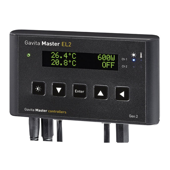
Introduction 1.1. Product description The Gavita Master controller EL2 is a dual channel controller which can control up to 80 ballasts/lights in climate rooms. Unlike a switchboard, which switches the power supply of regular ballasts on and off, the controller can control appropriate Gavita e-series ballasts by means of a low voltage control signal. -
Page 8: Glossary Of Terminology
instant messaging. An alarm will be triggered by temperature shutdown, sensor failure or power failure. The controller is equipped with a 16x2 character green OLED display, which ensures high contrast and clarity in dark and light environments. It provides a self-explaining menu system with a full text interface for extremely easy and intuitive use. -
Page 9: Product Specifications
Product specifications 2.1. General product information Product name Master Controller EL2 Product code 60.56.00.xx.xx Producer Gavita Holland bv 2.2. Technical specifications Controller dimensions (LxWxH) 127 x 22 x 75 mm Weight 170 gram Adapter: 100V-240V AC 50/60hz - Power supply... -
Page 10: Components
2.5. Components Gavita Master controller EL2 Mounting plate 2x Countersunk screw 2x Plug Manual 120-240V AC - 5V DC power adapter (2000mA) 2x Controller cable (5m/16ft) RJ14 (6P4C) plug (connect to ballasts) RJ9 (4P4C) plug (connect to controller) 2x Temperature sensor with cable (5m/16ft) 2.6. -
Page 11: Indications
2.7. Indications For more information on indications go to chapter 7 Indication signal Function A burning green light indicates controller is active. A Power indication A blinking green light indicates a power interruption has occured during operation. B Display Displays status, warnings and controller menu. Light indication A burning blue light indicates the port is active. -
Page 12: Connections
2.8. Connections F G H 5V DC input 3,5 mm jack main temperature sensor (T1) RJ9 (4P4C) Main port for controlling up to 40 ballasts Cage clamp connector ECM1 (output is active when main channel is on) Cage clamp connector ECM2 (output is active when main channel is off) Cage clamp alarm Normally Open (potential free contact) Cage clamp alarm Normally Closed (potential free contact) RJ9 (4P4C) Auxiliary port for controlling up to 40 ballasts... -
Page 13: Accessories
2.10. Compatible ballasts Note: Ballasts are not included, they have to be bought separately. Visit the website of Gavita Holland: www.gavita-holland.com for the latest Gavita products. The Gavita Master controller EL2 is compatible with all Gavita e-series ballasts. -
Page 14: Safety Guidelines And Measures
Doing so will void the warranty. Warning! The ECM channels of the Gavita Master controller EL2 may only be connected to Gavita ECMs. Do not connect the Controller to other products as this may lead to malfunctions or damage and can be dangerous. -
Page 15: Installing And Connecting The Temperature Sensor(S)
4.2. Installing and connecting the temperature sensor(s) Warning! The Gavita Master controller is not a climate controller. Do not use the product to manage the temperature in your climate room. Caution! Only use Gavita temperature sensors. Caution! Ensure the controller measures the same temperature as the climate control system (see paragraph 5.2). -
Page 16: Installing The Temperature Sensor In "Follow Mode" (One Room)
Installing the temperature sensor in “Follow mode” (one room) 4.2.1. Only one of the provided temperature sensors is needed in “Follow mode”. • Place the provided temperature sensor as close as possible to the sensor of the existing climate control system, so both sensors will measure the same temperature (4A) •... -
Page 17: Installing The Temperature Sensors In "Inverse Mode" (Two Rooms)
Installing the temperature sensors in “Inverse mode” (two rooms) 4.2.2. Two temperature sensors are needed in “Inverse mode”. • Before placing the temperature sensors, determine which controller channel (main/aux) controls the lights in which room (“main” room/“aux” room) (5) • Place one temperature sensor in each room. -
Page 18: Connecting The Controller To The Ballasts
Warning! Ensure the remote ballasts are connected to their lamps and reflectors. • Switch the rotary knob on all Gavita ballasts to “EXT” (external control) • Plug the RJ9 end of one of the controller cable(s) (6A) into the RJ9 main port of the controller. -
Page 19: Connecting The Controller To Complete Fixtures
Note: A RJ14 splitter and two cables are provided with each complete fixture since complete fixtures have only one RJ14 port. • Switch the rotary knob on all Gavita ballasts to “EXT” • Plug the RJ9 end of one of the provided controller cable into the RJ9 main port of the controller (7A) •... -
Page 20: Shortening Rj Cables
(local) cabling before connecting a load to the ECM. Warning! Never connect the cage clamps of the ECM to any other device than the Gavita EL2 controller. Warning! Never connect more then one ECM to each set of cage clamps of... -
Page 21: Connecting The Signal Cable To The Controller And The Ecm(S)
Warning! Ensure all wire ends are fully inserted into the cage clamps. Exposed wire endings can be dangerous! Caution! To prevent potential crop damage, ECMs are automatically shut down after a temperature alarm, a sensor failure or during a power interruption. -
Page 22: Controlling Auxiliary Equipment In "Follow Mode" (One Room)
Controlling auxiliary equipment in “Follow mode” (one room) 4.4.2. Caution! Gavita recommends you install and connect the ECM before plugging it into the mains. Note: When activated, the blue light on the ECM will burn. ECM1 ECM2 Main Auxiliary Auxiliary... -
Page 23: Connecting Equipment Which Must Be Used During Lights-Off Periods
ECM connected to clamps marked “ECM2”. Controlling auxiliary equipment in “Inverse mode” (two rooms 12h/12h) 4.4.3. Caution! Gavita recommends you install and connect the ECM before plugging it into the mains. Note: Two ECMs are needed for a two room setup. -
Page 24: Connecting Equipment Which Must Be Used During Lights-On Periods
4.4.3.1. Connecting equipment which must be used during lights-on periods Example: a CO source, light or watering unit may be activated during lights-on periods. • Connect the auxiliary equipment in the “main” room which must be activated during lights-on periods to the ECM connected to clamps “ECM1”... -
Page 25: Connecting An Alarm Wire To The Controller
Connecting an alarm wire to the controller 4.5.1. • To connect an alarm to a cage clamp, take the wire from the alarm, split it in two and strip the ends bare. The endings need to be stripped 8mm and preferably be tinned or finished with cable end sleeves •... -
Page 26: Connecting The Controller To The Mains
4.6. Connecting the controller to the mains Warning! When you power on the controller, the connected ballasts may ignite. Either: a) make sure your ballasts are not connected to mains yet or b) the signal cable of the ballasts is not inserted in the controller yet before connecting and programming the controller. -
Page 27: Preparations Before Use
Preparations before use Caution! Set the controllers output mode to “OFF” (see paragraph 6.6.) to ensure no ballasts will be accidentally activated during the controller setup. After this it is safe to either connect the ballasts to mains or insert the signal cable to the ballasts into the controller. -
Page 28: Switch Temperature Units Between Fahrenheit And Celsius
If these values do not match, the temperature safety system of the Gavita controller may interfere with the climate control system. Caution! Always place the temperature sensor of the controller as close as possible to the temperature sensor of the climate control system. -
Page 29: Change The Display Mode From The Controller Output From % To Watts
Calibrating the temperature sensor • Use the arrow keys to switch between “T1” or “T2” and press “enter” to select the temperature value you wish to adjust • Use the arrow keys to adjust the temperature to the desired value and press “enter”... -
Page 30: Programming And Using The Controller
Default output display • Press “enter”, the controller menu will open • Press the arrow keys to locate “Display mode” and press “enter”. The “Display mode” screen opens • Press the arrow keys to select which type of ballasts you have connected: 400W, 600W, 750W, 1000W, or select percentage in a mixed environment •... -
Page 31: Adjust Ballast Output To Change Light Intensity
• Set the shutdown temperature (see paragraph 6.4.2) • Set sunrise/sunset period (optional) (see paragraph 6.5) • Activate the auto mode on the controller (see 6.6.). 6.1. Adjust ballast output to change light intensity The controller can set the output of a ballast between 50 and 115 percent. Adjusting this ballast output enables the user to change the light intensity in the climate room. -
Page 32: Set Follow- Or Inverse Mode (Aux Function)
Programming a light cycle 6.3. Set follow- or inverse mode (aux function) The controller can be set to activate and deactivate all ballasts connected to it simultaneously. In this manual, this mode will be referred to as the “Follow Mode”. The controller may also be set to invert the output of its main and the auxiliary channel. -
Page 33: Set Temperature Safety Settings
6.4. Set temperature safety settings When the temperature in a climate room gets above a certain value, the planted crops will start to degrade. If this rise in temperature occurs, it is desirable to dim or shut down the lights in the climate room to reduce the temperature in the room. -
Page 34: Setting Safety Shutdown Temperature
• Press “enter”, the controller menu will open • Press the arrow keys to locate “Auto-Dim Temp” and press “enter”. The auto-dim temperature screen opens • Press the arrow keys to increase or decrease the temperature. • Press “enter” to confirm. Once the auto-dim temperature is reached, the controller will automatically start dimming the lights. -
Page 35: Activate Or Deactivate The Lights Manually Or Set Automatic Mode
6.6. Activate or deactivate the lights manually or set automatic mode Warning! When replacing a light, setting the ballast to “Off” to override the clock is insufficient! ALWAYS disconnect the ballast from the mains. Warning! When the controller “Output mode” is set to “on” or “off”, the temperature safety features of the controller will not work. -
Page 36: Interpreting Controller Information
Interpreting controller information 7.1. Reading the default screen The default screen displays the temperature measured by one or two temperature sensors (21A). The screen also displays the output of both its channels, either in % or in Watts (21B). If an error occurs, it may also be displayed in the display. -
Page 37: Green Light (22A)
Green light (22A) 7.3.1. A burning green light indicates the controller is functioning. A blinking green light indicates the power has been interrupted. After a power failure the blinking green indicator must be reset; • Hold the reset button for three seconds to reset the indicator. Blue light (22C/22D) 7.3.2. -
Page 38: Auto-Dim
RJ4 connector paragraph 4.3.3). 7.5. View the software version on the controller Your reseller or Gavita Holland bv may request the software version of your controller to check for compatibility with (future) Gavita products. •... -
Page 39: Maintenance And Repair
If the product shows any defects within this period and that defect is not due to user error or improper use Gavita Holland shall, at its discretion, either replace or repair the product using suitable new or reconditioned products or parts. -
Page 40: Appendix I - Overview Of All Screens On Display
Appendix I – Overview of all screens on display...
Need help?
Do you have a question about the Master EL2 and is the answer not in the manual?
Questions and answers