Table of Contents
Advertisement
Quick Links
SIM908 Document
Note: This device complies with part 15 Rules. Operation is subject to the following two conditions: (1) This
device may not cause harmful interference, and (2) this device must accept any interference received, including
interference that may cause undesired operation.
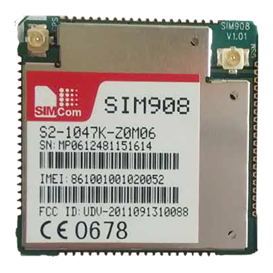
If this equipment is installed in a host, We can find the ID label when opening the host. For label requirement
when transmitter module is installed in a host, the host shall have an additional permanent label referring to the
enclosed module:"Contains Transmitter Module FCC ID: UDV-2011091310088" or "Contains FCC ID:
UDV-2011091310088".
This equipment has a GSM antenna and a GPS antenna, the GPS antenna peak gain is 5 dBi and modulation
type is BPSK; the GSM antenna peak gain is 3 dBi and modulation type is GMSK.
WARNING: Changes or modifications to this unit not expressly approved by the party responsible for
compliance could void the user's authority to operate the equipment. The antenna of the product, under normal
use condition is at least 24.22 cm away from the body of the user,the user must keeping at least 24.22cm
distance to the antenna.
The device has been evaluated to meet general RF exposure requirement. The device can be used in portable
exposure condition without restriction.
1. SIM908 Description
1.1 Summarize
Designed for global market, SIM908 is integrated with a high performance GSM/GPRS engine and a GPS engine.
The GSM/GPRS engine is a quad-band GSM/GPRS module that works on frequencies GSM 850MHz, EGSM
900MHz, DCS 1800MHz and PCS 1900MHz. SIM908 features GPRS multi-slot class 10/ class 8 (optional) and
supports the GPRS coding schemes CS-1, CS-2, CS-3 and CS-4. The GPS solution offers best- in-class
acquisition and tracing sensitivity, Time-To-First-Fix (TTFF) and accuracy.
With a tiny configuration of 30*30*3.2mm, SIM908 can meet almost all the space requirements in user
applications, such as M2M, smart phone, PDA, tracker and other mobile devices.
SIM908 has 80 SMT pads, and provides all hardware interfaces between the module and customers' boards.
Serial port and debug port can help user easily develop user's applications.
GPS Serial port.
Two audio channels include two audio inputs and two audio outputs. These can be easily configured by AT
command.
Charging interface.
Programmable general purpose input and output.
The keypad and SPI display interfaces will give users the flexibility to develop customized applications.
RF pad and connector interface.
SIM908 is designed with power saving technique so that the current consumption is as low as 1.0mA in sleep
SIM908 User Manual
- 1 -
Advertisement
Table of Contents

Related Manuals for SimCom SIM908


Summary of Contents for SimCom SIM908
- Page 1 The keypad and SPI display interfaces will give users the flexibility to develop customized applications. RF pad and connector interface. SIM908 is designed with power saving technique so that the current consumption is as low as 1.0mA in sleep - 1 -...
- Page 2 SIM908 Document mode (GPS engine is powered down). SIM908 integrates TCP/IP protocol and extended TCP/IP AT commands which are very useful for data transfer applications. 1.2 SIM908 Key Features Table 1: SIM908 GSM/GPRS engine key features Feature Implementation Power supply 3.4V ~ 4.5V...
- Page 3 Support RTC Size: 30*30*3.2mm Physical characteristics Weight: 5.2g Firmware upgrade Firmware upgradeable by debug port. SIM908 does work at this temperature, but some radio frequency characteristics may deviate from the GSM specification. Table 2: GPS engine Performance Performance Parameter Description...
- Page 4 SIM908 Document Velocity 1850 km/h Tracking CA Code Protocol support NMEA,OSP Continuous tracking Power consumption acquisition Power down 0.03 current Table 3: Coding schemes and maximum net data rates over air interface Coding scheme 1 timeslot 2 timeslot 4 timeslot CS-1 9.05kbps...
-
Page 5: Package Information
TOP VIEW PWM2 PWM1 GPS/DBG-TXD GPS/DBG-RXD SIM-DATA VDD-EXD SIM-RST SIM-CLK VRTC SIM-VDD Figure 1: SIM908 pin out diagram (Top view) 2.2 Pin Description Table 4: Pin description Pin name Pin number Description Comment Power supply VBAT 62, 63 Power supply 3.2V ~ 4.8V... - Page 6 SIM908 Document VDD-EXT 2.8V output power supply If it is unused, keep open. GPS-VANT-OUT 2.8V output for GPS active antenna If it is unused, keep open. GPS-VANT-IN GPS active antenna power supply If it is unused, keep open. 1, 2, 5, 10, 14, 37,...
- Page 7 SIM908 Document GPIO4/KBC0 GPIO4/keypad column 0 GPIO5/KBC1 GPIO5/keypad column 1 GPIO6/KBC2 GPIO6/keypad column 3 Serial port Receive data Transmit data If only TXD and RXD Request to send are used, it is suggested to pull down DTR, and Clear to send...
-
Page 8: Package Dimensions
SIM908 Document 2.3 Package Dimensions Figure 2: Dimensions of SIM908(Unit: mm) Figure 3: Recommended PCB footprint outline(Unit: mm) - 8 -... - Page 9 SIM908 Document 2.4 Pictures GPS PAD Antenna connector Antenna connector GSM PAD Figure 4: The RF interface of module 3. Detail Block Diagram Figure 5: Block diagram of SIM908 - 9 -...
- Page 10 4. Electrical and Reliability Characteristics 4.1 Absolute Maximum Ratings The absolute maximum ratings stated in following table are stress ratings under non-operating conditions. Stresses beyond any of these limits will cause permanent damage to SIM908. Table 5: Absolute maximum ratings Symbol...
- Page 11 SIM908 Document 4.4 SIM Card Interface Characteristics Table 8: SIM card interface characteristics Symbol Parameter Unit High-level input current Low-level input current High-level input voltage Low-level input voltage High-level output voltage Low-level output voltage 4.5 VDD_EXT Characteristics Table 9: VDD_EXT characteristics...
- Page 12 SIM908 Document VRTC input current RTC-IN VRTC output voltage 3.00 RTC-OUT VRTC output current RTC-OUT 4.8 Current Consumption (VBAT = 3.8V, GPS engine is powered down) Table 12: GSM current consumption Symbol Parameter Conditions Value Unit VRTC current VBAT disconnects. Backup battery is 3 V...
-
Page 13: Electrostatic Discharge
During Tx burst VBAT-peak 4.9 Electro-Static Discharge SIM908 is an ESD sensitive component, so more attention should be paid to the procedure of handling and packaging. The ESD test results are shown in the following table. ℃ Table 13 : The ESD characteristics (Temperature: 25 , Humidity: 45 %) - Page 14 ±5 ±6 ±5 ±6 ±5 ±6 19-31 ±5 ±6 Table 15 : SIM908 DCS 1800 and PCS 1900 conducted RF output power DCS 1800 and PCS 1900 Tolerance (dB) for conditions Nominal output power (dBm) Normal Extreme ±2 ±2.5 ±3 ±4...
- Page 15 30dBm, and at the maximum power level, the output power tolerance should not exceed +/-2dB under normal condition and +/-2.5dB under extreme condition. 4.10.2 Module RF Receive Sensitivity The following table shows the module’s conducted receive sensitivity, it is tested under static condition. Table 16 : SIM908 conducted RF receive sensitivity Frequency Receive sensitivity(Typical) Receive sensitivity(Max)
Need help?
Do you have a question about the SIM908 and is the answer not in the manual?
Questions and answers