Technische Alternative UVR1611 Manual
Freely, universal
Hide thumbs
Also See for UVR1611:
- Installation instructions manual (120 pages) ,
- Operation, programming, installation instructions (120 pages)
Table of Contents
Advertisement
Quick Links
Technische Alternative
elektronische Steuerungsgerätegesellschaft mbH.
A-3872 Amaliendorf, Langestr. 124, Fax 02862 53635 7
FREELY PROGRAMMABLE UNIVERSAL
The UVR1611 unit is equipped with function modules offering the possibility of free programming
for each system configuration for heating space management. As each function module can be called
repeatedly, complex control systems such as solar systems with multiple collector panels and tanks or
multiple heating circuits controlled by atmospheric conditions can also be realised.
It offers the following features:
16 sensor inputs for KTY10 or PT1000 sensors
(two of them also serving as pulse input and analogue input 4-20mA or 0-10V)
4 speed-adjustable outputs and 7 relay outputs
2 other outputs upgradable via a relay module
Operation via scroll-wheel and large display
2 control outputs 0-10 V separately switchable to PWM
CAN-Bus for data exchange to other and/or additional UVR1611 units
DL-Bus to capture respective sensors and to record data
Infrared interface for software updates
CONTROLLER
UVR1611
Vers. A3.17EN
Advertisement
Table of Contents

Related Manuals for Technische Alternative UVR1611


Summary of Contents for Technische Alternative UVR1611
- Page 1 FREELY PROGRAMMABLE UNIVERSAL CONTROLLER The UVR1611 unit is equipped with function modules offering the possibility of free programming for each system configuration for heating space management. As each function module can be called repeatedly, complex control systems such as solar systems with multiple collector panels and tanks or multiple heating circuits controlled by atmospheric conditions can also be realised.
- Page 3 It serves especially as a programming tool while operating the unit. Even using the TAPPS – system (the „Technische Alternative Planning and Programming System”) which you can find on our homepage www.ta.co.at, it is sometimes to know the programming mechanisms of the unit in order to be able to make local changes remotely.
-
Page 4: Table Of Contents
Contents: Planning basics ........................6 Basic standards ........................7 The basic operation ....................7 The display ......................7 The keys ......................7 The scroll-wheel....................8 Terms used ......................8 The user interface ......................9 MENU User ......................11 MENU Date / Time ....................13 MENU Measured values overview ................ - Page 5 Installation instructions ....................106 Sensor installation ....................106 Installing the device....................108 Cables and network topology .................109 Electrical connection ....................111 Function mode ....................113 Technical data UVR1611 ................113 Quantity delivered ...................113 Accessories ........................114 TAPPS ......................114 Hirel 1611:.......................114 CAN I/O module 44 and CAN I/O 35:............114 CAN Monitor: ....................114...
-
Page 6: Planning Basics
Planning basics To ensure efficient programming, the following order has to be observed: The basic condition of writing the desired controller functions and its parameterizing is an accurate hydraulic diagram! This diagram must show what should be regulated and how. The sensor positions are to be defined according to the desired controller functions and drawn into the diagram. -
Page 7: Basic Standards
Basics Basic standards The basic operation The display The display consists of four information fields The top line constantly provides information about the actual output states. Blank field instead of number 5 = output five has not yet been parameterized Output five is active, runs in automatic mode and is temporarily switched off Output five is active, runs in automatic mode and is temporarily switched on Output five is active, runs in manual mode and is temporarily switched off... -
Page 8: The Scroll-Wheel
Basics The scroll-wheel By means of the scroll-wheel, the selected menu can be gone through by the right pointer in the dis- play. Small upward or downward showing arrows symbolize the possibility of further menu lines above or below the visible display range. If a parameter is to be changed, the pointer must be put in the desired position. -
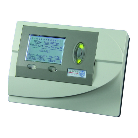
Page 9: The User Interface
TECHN. ALTERNATIVE ---------------------- Homepage: www.ta.co.at ---------------------- UVR1611 Operat.Syst: Ax.xxEN Operating system: Version number of the software. The latest software (higher number) is available for download under http://www.ta.co.at. It can be transferred to the control unit by means of accessory equipment – the boot loader. - Page 10 Main menu Version – shows only the same indication as after the starting up - i.e. the operating system of the unit. User – This menu permits the adjustment of the control level, the indication contrast and the back- ground lighting as well as the entrance into a so-called “User interface editor”, which allows the crea- tion of an own menu surface.
-
Page 11: Menu User
Menu User MENU User Here the following entries are listed: USER ---------------------- OPERATING MODE: Client Technician Expert and by scrolling downwards: DISPLAY: Contrast: Brightness: Illuminat. Off after deactivated 00 sec. Automatic Switch to Funct.Overview: USER INTERF.EDIT DATE / TIME: Automatic Time Switch Normal/Summer: Time Since Leaving... - Page 12 The attenuation of the 12V relays to the 5V computer tension in many devices is transformed into heat, but in case of the UVR1611 also into light! Thus disconnect- ing does not save energy. The intensity of the background lighting is variable and can be switched off after an adjustable time, while no control element is used.
-
Page 13: Menu Date / Time
Menu Date/Timer Menu Measured values overview MENU Date / Time Here the following entries are listed: DATE / TIME ---------------------- Friday 24.04. 2009 Normal time: 00 : 00 All values can be selected and changed accordingly by means of the scroll-wheel (pressing the wheel - frame = orange –... -
Page 14: Menu Function Overview
Menu Function overview MENU Function overview All of the function modules offer a wide range of information, measurement values, and parameters that can be viewed via the menu "Functions." To give users a quick overview of the main settings, experts can use the "user interface editor" to display all of the information that users need to see from all the menus. -
Page 15: The User Interface Editor
Menu Function overview The user interface editor To keep the dialogue between users and the controller as simple as possible, an overview menu is automatically provided to present the most essential information that users need to know from the wide array of information available. - Page 16 Menu Function overview Programming example: The example we will start with in the function overview is the date, the time (both of which users can change), and the collector temperature. Enter the command S (source). Now, the display shows: User User is a special feature as it does not have anything to do with commands or entries and is the only source information that does not produce a heading.
-
Page 17: Tips And Tricks
Menu Function overview Tips and tricks The commands Delete < and Insert > acquire the inputs of the number of lines. The overview is all the more useful for users if the information is provided in a proper sequence. Begin with the functions for maintenance and control of the heater. -
Page 18: The Parameterizing Of The Inputs
Menu Inputs The parameterizing of the inputs The menu "Inputs“ primarily serves as overview over the measured values of the inputs and/or sensors. Furthermore, it allows the expert the parameterizing of all used inputs if employed the following pro- cedure: The line “Inputs”... - Page 19 Menu Inputs In the next step the name (designator) Buffer, bottom is to be assigned to the input 4. To do so, superset “designator groups” were specified such as General, Producer, Consumer, Pipe, Climate and others. General is a group which had to be taken over from old operating systems (< A1.21). Many names out of it are represented also in the other groups.
-
Page 20: Special Abilities Of The Inputs
Menu Inputs Special abilities of the inputs The inputs also permit as measured analogue variable Voltage including the necessary scaling. By this the determination of the value range is to be effected with a separate indication for the limit of the minimum and maximum input signal. -
Page 21: Connection Of An Electronic Sensor (Vfs2-40, Rps0-6)
Menu Inputs With “TYPE“ Pulse and “MEAS VAR” Pulse there is also available a “PRESCALER” at the inputs 15 and 16. It indicates how many pulses have to arise at the input, so that a pulse is passed on to the functions. -
Page 22: The Parameterizing Of The Ouputs
Menu Outputs The parameterizing of the outputs The menu "Outputs“ primarily serves for the switching between the automatic and manual mode of the outputs. As in the status line of the outputs (top symbol line on the display) it is not possible to share information concerning the speed stages (if active), this indication was put down in the output menu. - Page 23 Menu Outputs After selecting the type (such as RPM OUTPUT, since a solar pump shall run speed-controlled at output 1 later on) all available parameter lines are faded in. OUTPUT STATUS: TYPE: RPM OUTPUT DESIGNATION GROUP: General DES: ------- (This line is suppressed in SWITCH OUTP) MODE: Wave Packet Rise-delay time...
-
Page 24: Particularities Of Output 14
DL. In this case the data logger recognises the second data packet as virtual second UVR1611 controller. However this option can only be used if the data logger's second DL input is unused. -
Page 25: Particularities Of The Outputs 15, 16
Menu Outputs Particularities of the outputs 15, 16 Output 15, 16 = analogue output. This output provides a voltage of 0 to 10V for the performance control of modern boilers (boiler modulation) and is usually controlled from a PID function module. The "scaling"... -
Page 26: Menu Functions
Menu Functions MENU Functions The basic standards of the function menu In the menu “Functions“ all linkages concerning the control are to be set and parameterized (therein the control engineering of the entire solar and heating installation is described!). To this end, the unit has a set of function modules which can be registered successively and also several times in the list “Functions”. - Page 27 Menu Functions The following modules are available at present: Solar thermal con- Differential controller including various auxiliary functions trol Solar priority Priority assignment between multiple solar differential control- lers Start function Start help for solar thermal systems ...
- Page 28 Menu Functions The following example shows how to set a new function. Indication example from the menu Functions: The function module already has been 5: LOAD PUMP assigned to function 5 “Load pump” LD PUMP 1 PAR? 6: NEW FUNCTION PAR? ◄...
-
Page 29: Input Variables
Menu Functions Input variables Serve as link to sensors and also to eventually prepared output variables from other function modules or definable parameters. The collector and the tank sensor are the typical input variable of the module SOLAR CONTROL. Another typical input variable for the module REQ.HEATING is the calculated nominal temperature of the pre-run (T.Pre.NOM) of the module HEAT.CIRC.CONT. - Page 30 Menu Functions If another function module (also from the network) has been selected as a source, its first output vari- able (or network input variable) in the following. An analogue value (temperature, computation result) is not suitable for the enable control. A enable control only can be a switch, thus a digital value such as the output status of an already registered function module.
-
Page 31: Output Variables
Menu Functions Output variables represent the result of a function module. They can be used directly for the switching of a hardware output or serve as input variable for another module. If this output variable is to be used directly for the switching of a pump, the respective assignment can be made in the relative menu “OUTPUT VARIABLE”... - Page 32 Menu Functions A common pump with valves is often used in solar thermal systems with multiple consumers. There- fore, we assume the following: Double circuit solar thermal system with common pump and three-way valve Output 1 = Common pump Output 3 = Three-way valve In this example both the output 1 and the output 3 have to be activated in SOLAR 2 (1 and 3 darkened).
-
Page 33: Typical Function Parameter
Menu Functions Function parameter Function parameters are set values which provide the user with the possibility to adapt the ready (i.e. with all preset function modules) control unit to the characteristics of his system. In the module SOLAR CONTROL these are parameters such as switch-on/off difference, maximum limit to the possible sensors (tank, top and bottom etc.). - Page 34 Menu Functions After entering the menu “TIME PROG:” all time programs are listed sequentially with their time windows. Indication example: Mo Tu We Th Fr Sa Su 05.00 - 07.00 12.00 - 22.00 Time window not used 00.00 - 00.00 If the first time program applies to the period from Monday to Friday, these five symbols are darkened after each other in the usual fashion (select, press, darken, press).
-
Page 35: Function Status
Menu Functions Functions that have already been entered can be deleted at any time. It is recommended that a function be deleted if function data are available from a similar project and the changes that have to be made are minor. To do so, you will find the command "DELETE FUNCTION" at the end of the menu in each function module. -
Page 36: Menu Messages
Menu Messages MENU Messages This module allows messages (error, malfunction, and others) to be triggered by specified events that last longer than 10 seconds. Any messages issued are automatically entered in the function overview. In addition, output variables provide switching signals as long as the message is current. A total of eight message lines can be set up, each of which should be understood as an independent module. - Page 37 Menu Messages INPUT VARIABLE: OUTPUT VARIABLE: What is the heading of the message? TYPE OF MESSAGE: A warning is issued WARNING What group was the name of the message selected from? MESSAGE GROUP: General or user-defined (only with TAPPS) Default What event caused the message to be issued? MESSAGE CAUSE: Excess temperature triggered the message...
-
Page 38: Menu Network
Autooperat. - If the network only consists of devices from the UVR1611- family (UVR1611, CAN monitor, BL-NET, etc.), autooperat. must be set to yes (normal case). If there is a master or network manager in the network, autooperat. -
Page 39: Output Variable
Menu Network Output variable A total of 16 digital and 16 analogue network outputs can be programmed. All of the input and output statuses, output variables for the functions, network status, sensor status, and the status of messages can be used. DIG. -
Page 40: Input Variable
Menu Network Input variable A total of 16 digital and 16 analog network inputs can be programmed. They are indicated by the transmission node number and the number of the network output variable of the transmission node. INPUT 1: NW.Node: Anal.NW.Outp.: Source: Value:... -
Page 41: Data Logging
Menu Network Data logging There are 2 data logging possibilities: Via the data link (DL-bus): When data logging via the DL-bus, there is a constant data flow from the controller to the boot loader BL-NET or data converter D-LOGG . The values or states of all inputs, switch outputs and the values of up to two heat quantity counters are specified as a data record. - Page 42 Menu Network Speed stages of the outputs: If the speed stages of an output are also to be captured, the digital value must have the same number as the corresponding output, e.g., output 6 must have been allocated digital value 6. If the output is allo- cated to another digital value, then status output still occurs (ON/OFF), but no speed stage output.
-
Page 43: Network Nodes
Revision number Node product description Des.: These data are fixed values specified by Technische Alternative GmbH and cannot be changed. Load menu page: This is used to access the menu level of the CAN MONITOR NODE 50 selected network node. The controller now serves as a display for this device. -
Page 44: Menu Data Administration
Menu Data administration MENU Data administration In this menu the commands concerning the administration and protection of the function data as well as the update of the operating system are listed. Current Funct. Data: Name of the current function data (TAPPS) TA FACTORY SETTINGS if function data have already been changed: modified Status: original... -
Page 45: Data Exchange With The Pc And/Or Boot Loader
Menu Data administration Create Backup Copy – The function data can be saved in a backup copy. By this, it is possible to change the program or the parameters without losing the existing function data. If a backup copy has been created, than appears as a further menu option: Load Backup Copy –... - Page 46 Menu Data administration DATA <=> BOOT LOADER: Download DATA – By means of the boot loader (accessory equip- ment) the protected function data in the PC are transmitted into the control unit via the CAN Bus or the infrared interface and thus the current programming is overwritten. The call contains similar com- mands as the upload, however it is possible to choose between several “data targets”.
-
Page 47: The Description Of The Function Modules
The description of the function modules The following modules are available at present: Solar thermal control Differential controller including various auxiliary functions Solar priority Priority assignment between multiple solar differential control- lers Start function Start help for solar thermal systems Cooling function Cooling of an overheated solar tank during the night Heating circuit con-... -
Page 48: Solar Control
Solar control Solar control Basic diagram: Input variables: Output variables: Enable Solar Circuit Status Solar Circuit Indication of the output A of the basic diagram Collector Temperature = T.Coll Status MAX Limit Reached = tank limit has been reached Reference Temperature = T.Ref Limit Temperature = T.Lim Simple description of the function: Release of the solar pump A, if the temperature in the collector T.Coll is greater by a difference than... - Page 49 Solar control Entire menu view: DES: SOLAR1 FUNCTION STATUS: INPUT VARIABLE: OUTPUT VARIABLE: COLLECTOR TEMP.: Current collector temperature T.Coll.ACT: 74.3 °C Pump is blocked when T.Coll.MAX has been reached T.Coll.MAX: 130 °C Release at T.Coll.MAX minus hysteresis Hysteresis: REFERENCE TEMP: Current tank temperature (bottom/return) T.Ref.ACT: 65.7 °C...
-
Page 50: Solar Priority
Solar priority Solar priority In solar heating systems used to charge more than one consumer (such as a tank, a buffer, and a basin), priorities must be set for the various circuits. There are basically two sets of rules used for a system of priority and lower priority assignment. - Page 51 Solar priority Input variables: Output variables: Enable Solar Priority Status Rinsing Process Solar Radiation = Radiation sensor Indication of the output for the rinsing Functions Involved = Entry of all solar func- tions in the function list Special features: In this function blocks, the "functions involved" are not individual values, but rather entire func- tion module input variables.
-
Page 52: Start Function
Start function Start function Simple description of the function: Sometimes, the collector sensor is not immersed in the heated heat medium quickly enough. In other words, the system goes into operation too late. There may not always be enough gravity force if the collector fields are completely horizontal, if the connections between the absorber strips meander, and especially if vacuum tubes are used with forced circulation. -
Page 53: Cooling Function
Cooling function Cooling function Simple description of the function: Solar heating systems with partial solar heating produce more warm water in the summer than can be used. This function can be used at night to remove some of the excess energy from the lower section of the tank back into the collector when a critical temperature has been reached in the buffer tank by regulating the speed of circulation. -
Page 54: Heating Circuit Controller
Heating circuit controller Heating circuit controller Basic diagram: Input variable: Output variable: Enable Heating Circuit Controller Nominal Temp. of the Pre-run = Temperature Enable Pump of the pre-run calculated by the control unit T.Pre.NOM Enable Mixer Effect Nominal Temperature for Room = Valid Room Temperature = T.Room indoor temperature according to time program T.Room.EFF... - Page 55 Heating circuit controller Basic menu view: DES: HEAT.CIR.1 FUNCTION STATUS: INPUT VARIABLE: OUTPUT VARIABLE: The heater is controlled by a space sensor OPERAT.: RAS and is currently running in heating mode (NORMAL) NORMAL ROOM TEMPERATURE: Current room temperature T.RoomACT: 20.7 °C Desired room temperature doing lowering time T.RoomLOWER: 15 °C...
- Page 56 Heating circuit controller If the line to the external sensor (measuring value > 100°C) is interrupted, the heating circuit is switched off. In the worst-case scenario, the system may be damaged by frost. To prevent such dam- age, the heating circuit is operated according to a set outdoor temperature of 0°C if the outdoor tem- peratures are clearly too high, and MALFUNCTION is displayed under "OPERAT.:".
- Page 57 Heating circuit controller HEAT CURVE: The feed-line temperature is usually calculated from the outdoor temperature and the heating curve. An exception is the fixed value control. The feed-line is set in lowering mode to the listed temperature of +10°C and in heating mode to that of -20°C. The module allows you to set parameters for the heating curve in two ways: ...
- Page 58 Heating circuit controller AVERAGE of outdoor temperature: Sometimes, fluctuations in outdoor temperature may even not be desirable in calculation of pre-run temperature or when determining the disconnection of the heating pump. Therefore, a separate calcula- tion of the mean is available for the outdoor temperature to calculate the heating curve and the discon- nection of the pump.
-
Page 59: Mixer Control
Mixer control Mixer control Basic diagram: Input variables: Output variables: Enable Mixer Control Temperature = T.CtrlEFF, nominal Control Temperature = Indication of a temperature calculated by the controller from the sensor control temperature and the differential Nominal Value = Control to this value (+diff) Status Mixer = M, indication of the outputs Simple description of the function: This function allows a mixer to be constantly controlled for a nominal value. -
Page 60: Comparison
Comparison Comparison (Thermostat/differential function) Simple description of the function: Two (temperature) values, Va and Vb + differential, are compared to produce the two output variables Va > Vb and Va < Vb. Input variables: Output variables: Enable comparison Status Va > Vb + diff = Value a is greater than value b Comparative Value a = First comparison Status Va <... -
Page 61: Load Pump
Load pump Load pump Basic diagram: Input variables: Output variables: Enable Load Pump Status of the load pump = A Feeder Temperature = T.Feed Indication of the output A Reference Temperature = T.Ref Minimum Temp. Feeder = Min. threshold at T.Feed Maximum Ref. - Page 62 Load pump Entire menu view: DES: LD PUMP 1 FUNCTION STATUS: INPUT VARIABLE: OUTPUT VARIABLE: FEEDER TEMPERATURE: Current temperature of the "energy provider" T.Feed.ACT: 74.3 °C Basic switch-on threshold at sensor T.Feed T.Feed.MIN: 60 °C Switch-on differential to T.Feed.MIN (here, 65°C) DIFF.ON: Switch-off differential to T.Feed.MIN (here, 61°C) DIFF.OFF:...
-
Page 63: Heating Requirement
Heating requirement Heating requirement Basic diagram: Input variables: Output variables: Enable Heating Requirement Status Requirement Indication of the output A (= Enable burner) Requirement Temperature = T.Req Shut-off Temperature = T.Off Nom. Value Requirement = Min. threshold at T.Req Nom. Value Shut-off = Max. threshold at T.Off Simple description of the function: Release of burner A if temperature in the buffer tank at the top (requirement temperature T.Req) falls below the "nominal value requirement"... - Page 64 Heating requirement Eco operation: is related by "undercoverage" to a particular time span. The undercoverage stage always applies for 60 minutes. For a requirement temperature of 50°C an undercoverage of 20% has the following effect: requirement after 30 minutes below 30°C or below 40°C (= 20%) after an hour or below 45°C after 2 hours.
- Page 65 Heating requirement Entire menu view: DES: HEAT.REQ. FUNCTION STATUS: INPUT VARIABLE: OUTPUT VARIABLE: REQ. TEMPERATURE: Current temperature of the sensor T.Req T.Req.ACT: 64.3 °C (Switch-on) threshold value at sensor T.Req T.Req.NOM: 60 °C Switch-on differential to T.Req (here, 65°C) DIFF.ON: 5.0 K SHUT-OFF TEMP.: Current temperature of the sensor T.Off...
-
Page 66: Warm Water Requirement
Warm water requirement Warm water requirement Basic diagram: Input variables: Output variables: Enable Warm Water Requirement Effective Nominal Temperature = Time-related Warm Water Temperature = T.ww WW nominal value T.WW.EFF Nominal Temperature = Desired warm water Nominal Temperature = Desired tank temperature temperature T.WW.NOM Status Requirement, indication of the output A... - Page 67 Warm water requirement Neither thermostat threshold has hysteresis, but rather a common switch-on/off differential to the adjustable threshold value. Example: T.WW.NOM = 50°C DIFF. ON = 1.0 K DIFF.OFF = 8.0 K In other words, if the temperature falls below T.WW 51°C (= 50°C + 1°K), the output is activated, while it is switched off if the temperature exceeds 58°C (= 50°C + 8°k).
-
Page 68: Boiler Cascade
Boiler cascade Boiler cascade Simple description of the function: The coordination of up to three burner requirements based on runtime and delay time by comparing the current demand temperature with a common pre-run temperature. The indication of the functions involved (requirement modules) automatically gives the module per- mission to control the burner via its internal signals "burner requirement"... - Page 69 Boiler cascade If there is demand (pre-run temperature T.Pre.NOM skyrockets) and the nominal temperature is below the switch-on differential of the dominant boiler "Diff1 on," the first requirement is issued. If the nominal temperature remains under the switch-on differential for the second boiler after a certain delay has elapsed, a second requirement is issued.
-
Page 70: Circulation
Circulation Circulation Basic diagram: Input variables: Output variables: Enable Circulation pump Effective Circulation Return Temperature T.CR.EFF Circ. Return Temperature = T.Cr (takes into account also the mixing protection) Warm Water Temperature = T.ww Nominal Return Temperature = maximum Status Circulation, indication of the output temperature allowed at T.Cr Tank Temperature = T.Tk tank sensor for mixing protection... - Page 71 Circulation Entire menu view: DES: CIRCU FUNCTION STATUS: INPUT VARIABLE: OUTPUT VARIABLE: Switched to "pulse mode" (see special features) OPERAT.: Time CIRCU. RETURN: Current temperature of the return T.CR.ACT: 34.7 °C Nominal (maximum) temperature of the return T.CR.NOM: 40 °C Open the switch time menu TIME PROG: Switch-on differential to T.CR.NOM (here, 41°C)
-
Page 72: Pid Control (Speed Control)
PID control PID control (speed control) The PID control can be used to change the delivered quantity – i.e. the volume flow – of usual com- mercial circulating pumps. That allows the system to maintain temperatures (differences). It can be used not only for the speed control but also for the control of the burner performance and others. - Page 73 PID control Waveform Two waveforms are available for motor control (in the menu “Outputs”). Wave packet - only for circulating pumps with standard motor dimensions. Here, individual half- waves are blended in to the pump motor. The pump is run via pulses, an the “smooth running” of the motor is only due to the moment of inertia.
- Page 74 PID control Pump standstill The wave packet method (standard) allows the volume flow to be changed by a factor of 10 in 30 increments. If the flow rate is too low, return flaps may cause a standstill as well as a low output of the pump at low speeds of the control unit.
- Page 75 PID control Event control “overwrites” the results of speed control from other control processes. Hence, a set event can block the absolute value control or differential control. Example: Keeping the collector temperature at 60°C with the absolute value control is blocked when the tank has already reached 50°C at the top = the fast provision of warm water is complete and is now to be continued with full volume flow (and hence a lower temperature but slightly better efficiency).
-
Page 76: Analog Function
Analog function Analog function Basic diagram: Input variables: Output variables: Enable Analog Function Result Result if (Enable = Off) Indication of the RPM control output Analog Input Variables 1 - 6 Simple description of the function: According to the basic diagram it looks for the highest (lowest) value of the analog inputs. Besides the heating circuit and load pump module this modules represents an extremely versatile and important link to the burner requirement. - Page 77 Analog function Example of use: The greatest temperature that the system currently demands is calculated from the three functions "heating circuit 1." "heating circuit 2" (output variable = pre-run nominal value), and burner require- ment warm water (output variable = effective tank temperature) so that the burner requirement is later correctly compared to the buffer tank temperature.
-
Page 78: Profile Function
Profile function Profile function Basic diagram: Input variables: Output variables: Enable Profile Status Profile Active = Output ON when Nominal Value if (Enable = Off) nominal value is not zero Start Profile = Starting the time controlled process Indication of the output Stop Profile = Stopping the time controlled proc- Nominal Value = Value of the current stage Reset Profile = Reset to stage 0 (profile disabled) - Page 79 Profile function Although the profile stage is registered every 6 hours in the internal storage, it gets lost while loading new function data (load factory settings, load backup copy, data transfer from boot loader). If an internal cycle > 23.5 hours is set (such as heat drying of a pavement floor), profile stage 1 is saved in the internal memory immediately after the profile function starts.
-
Page 80: Logic Function
Logic function Logic function Basic diagram: Input variables: Output variables: Enable Logic Function Status Result, indication of the output Digital Input Variables 1 - 6 Status Inverse Result, indication of the output Simple description of the function: AND- function: Output = ON only if all inputs are ON. OR- function: Output = ON if at least one input is ON. - Page 81 Logic function Example: The heating circuit is to be released based on the two thermostat functions "comparison_1" and "com- parison_2" when one of the two (OR-function) is triggered. When this function was called, the number of input variables was already set at two. The following parameters are now set in the submenu INPUT VARIABLE: INPUT VARIABLE Input variable 1 is the output of the thermostat...
-
Page 82: Time Switch
Time switch Time switch Basic diagram: Input variables: Output variables: Enable Time Switch Nominal value (if a temperature is assigned to the time window) Status Time Condition Fullfilled Blocking Input Indication of the output Simple description of the function: There are a maximum of 5 time programs each with 3 time windows available per module. As a freely usable time switch clock this function can be employed in various ways. - Page 83 Time switch Example: Time switch with two time programs, each with three time windows Entire menu view: DES: TIME INPUT VARIABLE: OUTPUT VARIABLE: The first time program is active on all workdays Mo Tu We Th Fr Sa Su Switched on on workdays at 06:00 AM and off at 07:30 AM 06.00 - 07.30 etc.
-
Page 84: Timer
Timer Timer Basic diagram: Input variables: Output variables: Enable Timer Status Timer Output, indication of the output Trigger Input = Input signal for starting the Status Inverse Timer Output, indication of the timer output Duty Cycle = Relation between input and output signal Simple description of the function: Independent time elements can switch time sequences between functions. - Page 85 Timer After run: The ON signal at the trigger input is looped to the output. If the input drops (OFF), the output remains ON for the duration of the timer period. Delay: The ON signal at the trigger input is only passed on when the timer period at the output has elapsed.
- Page 86 Timer Instable: By indicating a switch-on and off time, a pulse generator is created without a trigger input. If the pulse-duty factor is also used for controls, it changes the switch-on time. The setting switch-off time = 0 is a special case: The switch-on time then corresponds to the entire period, and the pulse-duty factor to the relationship between the switch-on and the switch-off time Pulse: If the selected trigger slope occurs, the output for the timer time switches on.
-
Page 87: Synchronisation
Synchronisation Synchronisation Simple description of the function: This module provides an output variable relative to the date and time based on the date and time in- formation of the device. In this way, periodic signals that directly relate to the time, day of the week, date, or season and allow for date or time-specific releases are available to control other function mod- ules. -
Page 88: Heat Quantity Counter
Heat quantity counter Heat quantity counter Basic diagram: Input variables: Output variables: Enable Heat Quantity Counter Current Power Pre-run Temperature = T.Pre Count Kilowatt Hours Return Temperature = T.Ret Count Megawatt Hours Volume Flow = VF Counter Reset Simple description of the function: Calculation of the heat output and quantity via the temperature difference and volume flow with con- sideration of the share of frost protection in the heat medium. - Page 89 Heat quantity counter Overall submenu view - SERVICE MENU: RESET Reset the Heat COUNTER: HEAT QUANT.: Total heat quantity in kWh 123.4 kWh CALIBRATION Start command for calibration START: The heat counter has not been calibrated Status:UNCALIBRATED After calibration, the temperatures measured during calibration LOWER: 80.00 °C are displayed here...
-
Page 90: Counter
Counter Counter Simple description of the function: As a operating hours counter or pulse counter (such as for the burner requirement) this function repre- sents another service function. Input variables: Output variables: Enable Counter Count (Max. 6 digital) Input Variables Counter Reset Special features: ... -
Page 91: Maintenance
Maintenance Maintenance This function is intended as a service function for the chimney sweeper and/or as a simple burner switch for the exhaust measurement. The preset output (generally 100%) is switched on for the set time after the burner has been started. In addition, the heating circuits set in the input variables are activated with the maximum admissible pre-run temperature. -
Page 92: Function Control
Function control Function control In the solar and heating section, a number of functions perform important tasks that could lead to wrong reactions if there's a malfunction. For instance, if a defective tank sensor in the solar system detects temperatures that are too low, the solar system will run under false premises and take heat out of the tank. - Page 93 Function control Entire menu view: (no error) (with error) DES: FUNC CTRL DES: FUNC CTRL INPUT VARIABLE: INPUT VARIABLE: OUTPUT VARIABLE: OUTPUT VARIABLE: PARAMETER: PARAMETER: T.Collector T.CollectorRRORERROR 57.4 °C 9999 °C Interruption T.ST.Lower T.ST.Lower 48.9 °C 48.9 °C ERROR DIFFERENCE DIFFERENCE 8.5 K 9999 K...
-
Page 94: Typical Hydraulics As Factory Setting
Factory setting Typical hydraulics as factory setting The factory settings are based on the following hydraulic diagram for solar warm water system with a buffer and service water tank, a boiler fired with wood pellets or oil/gas, and two heating circuits: The assignments of sensors in outputs according to the diagram are based on the special properties of the various inputs and outputs. -
Page 95: Factory Settings Via Tapps
Factory setting The "REQUIREMENT HEATING" shows that the ANALOG FUNCTION (MAX = look for the highest temperature in the input variables) is required to determine the greater pre-run nominal tem- perature of the two heating circuits and the effective nominal warm water temperature. The two heating circuit pumps A3 and A4 should not be released unless the temperature in the boiler or the buffer is high enough. -
Page 96: Detailled Description Of The Factory Setting
Factory setting Detailled description of the factory setting The solar part: Function modules: Solar thermal control / SOLAR 1 Solar thermal control / SOLAR 2 Solar priority / SOLPRIOR. Solar thermal control / SOLAR 1 Input variables: Output variables: Enable Solar Circuit = User ON (constantly Status Solar Circuit = Output 1 enabled) Collector Temperature = Source: Input 1:... - Page 97 Factory setting DIFFERENCE COLL-REF: Switch-on differential T.Coll – T.Ref DIFF.ON: 7.0 K Switch-off differential T.Coll – T.Ref DIFF.OFF: 4.0 K LIMIT TEMPERATURE: Current temperature of the additional sensor T.Lim.ACT: 54.0 °C Blocked by the additional sensor T.Lim.MAX: 70 °C Release at T.Lim.MAX minus hysteresis Hysteresis: Options / special features: ...
-
Page 98: The Heating Control Unit Part
Factory setting The heating control unit part: Function modules: Heating circuit control / HEAT.CIR. 1 Heating circuit control / HEAT.CIR. 2 Heating circuit control / HEAT.CIR. 1: Input variables: Output variables: Enable Heating Circuit = User ON (constantly Nominal Temp. of the Pre-run = Temperature enabled) of the pre-run calculated by the control unit T.Pre.NOM... - Page 99 Factory setting Always at the beginning of the heating period according Rate time: 0 Min to time program Current desired room temperature = 20°C (current T.Room.EFF: 20°C heating operation) PRE-RUN TEMPERATURE: Current pre-run temperature T.Pre.ACT: 58.4 °C Calculated pre-run temperature T.Pre.NOM: 58.2 °C Settings for the calculation of the pre-run temperature...
-
Page 100: The Load Pump Section
Factory setting The load pump section: Function modules: Load pump / LD PUMP 1 Load pump / LD PUMP 2 Load pump / LD PUMP 3 Load pump / LD PUMP 2: Input variables: Output variables: Enable Pump = User ON (constantly enabled) Status of the Load Pump = Output Feeder Temperature = Source: Input 7: T.ST.Upper Reference Temperature = Source: Input 2: T. -
Page 101: The Burner Requirement Warm Water
Factory setting The burner requirement warm water: Function module: Requirement WW / WW_REQ. Input variables: Output variables: Enable Req WW = User ON (constantly Effective Nominal Temp = Desired warm water enabled) temp. T.WW.EFF Warm Water Temp. = Source: Input 2: Status Requirement = No output assignment T. -
Page 102: The Burner Requirement Heating
Factory setting The burner requirement heating: Some modules such as: HEATING CIRCUIT CONTROL or REQUIREMENT WW provide the cur- rent demand temperature as an output variable. The boiler (burner) should only be running if the buffer cannot cover one of the demand temperatures. Function modules: Analog function / MAX (on) Heating requirement / HEAT.REQ. - Page 103 Factory setting Requirement heating/HEAT.REQ. Input variables: Output variables: Enable Requirement Heating = User ON (con- Status Requirement = Output A5 stantly enabled) Requirement Temperature = Source: Input 7: T.ST.Upper Switch-off temp Source: Input T.ST.Center Nominal Value Requirement = Source: MAX(An) from previous function Nominal Value Switch-off Source: MAX(An) from previous function...
-
Page 104: Release Of The Heating Circuit Pumps
Factory setting Release of the heating circuit pumps: NOTICE: The method described below with comparison and logic functions is intended to explain the technol- ogy of linked modules and releases. This is the main reason it is included in the factory settings. In many cases, the free decision made by the heating control units suffices without a release of the feed temperatures. - Page 105 Factory setting Comparison function / MIN FUNC.2: Input variables: Output variables: Enable Comparison user ON (constantly en- Status Va > Vb + diff = No direct assignment abled) (= input variable of logic function OR) Comparative Value a = Source: Input 7: T.ST.Upper Comparative Value b = Source user Simple description of the function:...
-
Page 106: Installation Instructions
Installation instructions Installation instructions Sensor installation The sensors must be arranged and installed properly for the system to function correctly. To this end, make sure also that they are completely inserted in the immersion sleeves. The threaded cable connec- tions provided serve as a strain relief. The clip-on sensors must be insulated to protect them from being influenced by the ambient temperature. - Page 107 Installation instructions Warm water sensor: When the control system is used in warm water systems with an external heat exchanger and speed-controlled pump, changes in the amount of water have to be reacted to quickly. Hence, the warm water sensor has to be put directly on the heat exchanger’s outlet. A t-shaped connec- tor should be used to insert the ultrafast sensor (special accessory) in the outlet using an o-ring.
-
Page 108: Installing The Device
Installation instructions Installing the device WARNING! ALWAYS PULL THE MAINS PLUG BEFORE OPENING THE CASING! To open the console the control unit has to be separated from it as fol- lows: Use two big screwdrivers to remove the clamps (labeled 1 in the sketch to the left) and list the device out of the console with the screwdrivers. -
Page 109: Cables And Network Topology
0.5mm² and a line to line capacity of no more then 60 pF/meter and a charac- teristic impedance of 120 ohms. The bus speed of the UVR1611 is 50 kbit/s. Theoretically, the bus could be 500 m long and still ensure reliable transmission. The Unitronic®-Bus CAN 2x2x0.5 cable is recommended. - Page 110 Installation instructions Example: Connection of three network nodes with a 2x2-pin cable and termination of the end of the network nodes. Each CAN network has to have a 120 ohm bus terminal (done using a jumper) for the first and last participant in the network.
-
Page 111: Electrical Connection
Installation instructions Electrical connection It should only be made by a professional electrician in accordance with the relevant local guidelines. The sensor lines must not be laid in the same cable as the supply voltage (standard, regulations). In a commonly used cable channel, appropriate shielding has to be provided. Notice: The system has to be grounded properly to protect it from damage due to lightening. - Page 112 Installation instructions Caution: Output A5 is potential free – thus not connected with the supply voltage. Slot 1 is intended for the relay module for two other outputs (A12, 13).
-
Page 113: Function Mode
+5 to +45°C Quantity delivered UVR1611K: The UVR1611, console including all terminals, while attachment material, 2 ground terminals, 16 strain reliefs, operating instructions UVR1611S: Device with rear panel shaped as bushings, 2 ground terminals, 2 3-pin and 4 11-pin plug-... -
Page 114: Accessories
Boot loader BL-NET: To back up data, update operating systems, and log data 1) Back up all of the function data for the UVR1611 on a PC and second backup. 2) Update of the UVR1611's operating system 3) Data logging of temperatures and output conditions via DL and CAN bus... -
Page 115: Tips On Troubleshooting
Tips on troubleshooting If there is no display, there has been a power outage. First check the fuse (6.3A, quick-blow) that protects the device and the outputs (pumps, valves, etc.) from short circuits and the outputs in connec- tion with the integrated overvoltage protection. Realistic temperature values but outputs not operating properly indicate false settings or connec- tions. - Page 116 ≥ 20 W. If the speed-controlled outputs (A2, A6, A7) only control small loads, an additional parallel load or the subsequent RC component is necessary to make switching reliable. UVR1611 100nF/630V 100R/0,5W Contactor ...
-
Page 117: Maintenance
Maintenance The system does not require maintenance if handled and used properly. Use a cloth moistened with soft alcohol (such as spirit) to clean. Harsh solvents such as chlorethenes or tri-gases are not admissi- ble. As the components relevant to accuracy are not subjected to loads if used properly, long-term devia- tion is very low. - Page 120 Technische Alternative elektronische SteuerungsgerätegesellschaftmbH. A-3872 Amaliendorf Langestr. 124, Tel 02862 53635, Fax /7 --- www.ta.co.at --- © 2009...
Need help?
Do you have a question about the UVR1611 and is the answer not in the manual?
Questions and answers