Technische Alternative uvr1611 Installation Instructions Manual
Freely programmable universal
controller
Hide thumbs
Also See for uvr1611:
- Manual (120 pages) ,
- Operation, programming, installation instructions (120 pages)
Table of Contents
Advertisement
Quick Links
Download this manual
See also:
Manual
Advertisement
Table of Contents

Related Manuals for Technische Alternative uvr1611


Summary of Contents for Technische Alternative uvr1611
- Page 1 UVR 1611 Version A4.03 EN Manual version 2 Freely programmable universal controller Operation Programming Installation instructions...
- Page 3 It serves especially as a programming tool while operating the unit. Even using the TAPPS – system (the „Technische Alternative Planning and Programming System”) which you can find on our homepage www.ta.co.at, it is sometimes to know the programming mechanisms of the unit in order to be able to make local changes remotely.
-
Page 4: Table Of Contents
Contents Safety requirements ..........................6 Maintenance ............................. 6 Function mode ..........................6 Planning basics ........................... 7 Basic standards ........................... 8 Basic operation ..........................8 Display ............................8 Keys ............................. 8 Scroll-wheel ..........................9 Terms used ..........................9 User interface ............................. 10 MENU User ............................. - Page 5 Examples of different network versions ..................105 Cable selection and network topology ................... 107 Data link (DL bus) ..........................108 Electrical connection ........................109 Technical data UVR1611 ......................... 111 Accessories ............................112 Tips on troubleshooting ........................113 Troubleshooting in the CAN network ..................... 115 ...
-
Page 6: Safety Requirements
Safety requirements These instructions are intended exclusively for authorised contractors. All installation and wiring work on the controller must only be carried out in a zero volt state. The opening, connection and commissioning of the device may only be carried out by competent personnel. While doing so, they must observe all local safety requirements. -
Page 7: Planning Basics
Planning basics To ensure efficient programming, the following order has to be observed: The basic condition of writing the desired controller functions and its parameterizing is an accurate hydraulic diagram! This diagram must show what should be regulated and how. The sensor positions are to be defined according to the desired controller functions and drawn into the diagram. -
Page 8: Basic Standards
Basics Basic standards Basic operation Display The display consists of four information fields The top line constantly provides information about the actual output states. Blank field instead of number 5 = output five has not yet been parameterized Output five is active, runs in automatic mode and is temporarily switched off Output five is active, runs in automatic mode and is temporarily switched on Output five is active, runs in manual mode and is temporarily switched off Output five is active, runs in manual mode and is switched on at the moment... -
Page 9: Scroll-Wheel
Basics Scroll-wheel By means of the scroll-wheel, the selected menu can be gone through by the right pointer in the display. Small upward or downward showing arrows symbolize the possibility of further menu lines above or below the visible display range. If a parameter is to be changed, the pointer must be put in the desired position. -
Page 10: User Interface
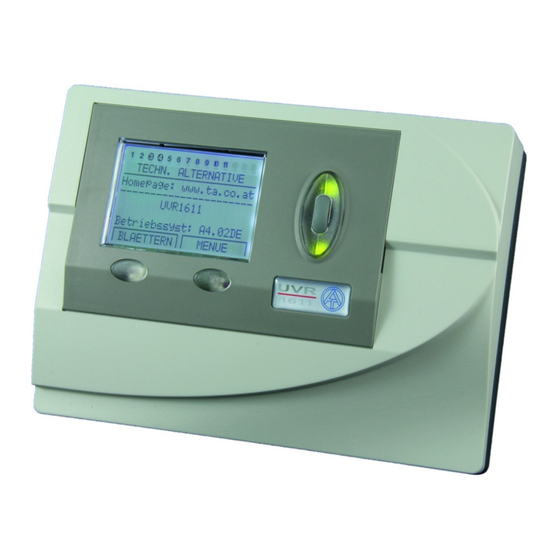
TECHN. ALTERNATIVE ---------------------- Homepage: www.ta.co.at ---------------------- UVR1611 Operat. sys: Ax.xxEN Operating system: Version number of the software. The latest software (higher number) is available for download under http://www.ta.co.at. It can be transferred to the control unit by means of accessory equipment –... - Page 11 Main menu Version – shows only the same indication as after the starting up - i.e. the operating system of the unit. User – This menu permits the adjustment of the control level, the indication contrast and the back- ground lighting as well as the entrance into a so-called “User interface editor”, which allows the crea- tion of an own menu surface.
-
Page 12: Menu User
Menu User MENU User Here the following entries are listed: USER ---------------------- OPERATING MODE: User Technician Expert and by scrolling downwards: DISPLAY: Contrast: Brightness: Illumin. off after deactivated 00 sec. autom. changeover to func. overview:yes DATE / TIME: aut. changeover std/ summertime: yes Time since leaving the expert level:... - Page 13 The attenuation of the 12V relays to the 5V computer tension in many devices is transformed into heat, but in case of the UVR1611 also into light! Thus disconnect- ing does not save energy. The intensity of the background lighting is variable and can be switched off after an adjustable time, while no control element is used.
-
Page 14: Menu Date / Time
Menu Date / time Menu Measurement overview MENU Date / time Here the following entries are listed: DATE / TIME ---------------------- Thursday 16. 12. 2010 Std time: 00 : 00 All values can be selected and changed accordingly by means of the scroll-wheel. The date and time function has a power reverse of approximately three days in case of a blackout. -
Page 15: Menu Function Overview
Menu Function overview MENU Function overview All of the function modules offer a wide range of information, measurement values, and parameters that can be viewed via the menu "Functions." To give users a quick overview of the main settings, experts can use the "user interface editor" to display all of the information that users need to see from all the menus. -
Page 16: The User Interface Editor
Menu Function overview The user interface editor To keep the dialogue between users and the controller as simple as possible, an overview menu is automatically provided to present the most essential information that users need to know from the wide array of information available. The FUNCTION OVERVIEW serves that purpose in this device. Experts can use the "user interface editor"... - Page 17 Menu Function overview Programming example: The example in the function overview we will start with is the date, the time (both of which users can change), and the collector temperature. Enter the command S (source). Now, the display shows: User User is a special feature as it does not have anything to do with commands or entries and is the only source information that does not produce a heading.
-
Page 18: Tips And Tricks
Menu Function overview Tips and tricks The commands Delete < and Insert > acquire the inputs of the number of lines. The overview is all the more useful for users if the information is provided in a proper se- quence. -
Page 19: Menu Inputs
Menu Inputs MENU Inputs The menu "Inputs“ primarily serves as overview over the measured values of the inputs and/or sen- sors. Furthermore, it allows the expert the parameterizing of all used inputs if employed the following procedure: The line “Inputs” has already been selected and then pressed the scroll-wheel. Hereby the indication example is as follows: 1: T.collector The temperature of the collector is currently... - Page 20 Menu Inputs In the next step the name (designator) Buffer, bottom is to be assigned to the input 4. To do so, su- perset “designator groups” were specified such as General, Generator, Consumer, Line, Climate and others. General is a group which had to be taken over from old operating systems (< A1.21). Many names out of it are represented also in the other groups.
-
Page 21: Special Abilities Of The Inputs
Menu Inputs Special abilities of the inputs The inputs also permit as measured analogue variable Voltage including the necessary scaling. By this the determination of the value range is to be effected. For program reasons, the same configuration options are available with all inputs for the voltage measurement value. -
Page 22: Connection Of Electronic Sensors In Version Dl
Menu Inputs With “TYPE“ Pulse and “MEAS.VAR” Impulse there is also available a “DIVIDER” at the inputs 15 and 16. It indicates how many pulses have to arise at the input, so that a pulse is passed on to the functions. -
Page 23: Menu Outputs
Menu Outputs MENU Outputs The menu "Outputs“ primarily serves for the switching between the automatic and manual mode of the outputs. As in the status line of the outputs (top symbol line on the display) it is not possible to share information concerning the speed stages (if active), this indication was put down in the output menu. - Page 24 Menu Outputs After selecting the type (such as SPEED CTRL, since a solar pump shall run speed-controlled at output 1 later on) all available parameter lines are faded in. OUTPUT STATUS: TYPE: SPEED CTRL DESIGNATOR GROUP: General DES: ------- MODE: Wave packet (This line is suppressed in SWITCH OUTP) DELAY:...
-
Page 25: Particularities Of Output 14
If the control receives data via the network, it is possible to send a second data record with the net- work input data via DL. In this case the data logger recognises the second data record as a virtual second UVR1611 controller. However this option can only be used if the data logger's second DL input is unused. -
Page 26: Particularities Of Outputs 15, 16
Menu Outputs Particularities of outputs 15, 16 Output 15, 16 = analogue outputs. These outputs provide a voltage between 0 and 10V for perfor- mance control of modern burners (burner modulation). They can be controlled by a PID function module, but also by other functions with an analogue value. The "scaling" offers the possibility of adapting the arithmetic value to the control range of the downstream device. -
Page 27: Anti-Blocking Protection
Menu Outputs Anti-Blocking Protection Circulating pumps, which do not run for longer periods (such as: heating circuit pump during the summer), often have starting problems as a result of inner corrosion. This problem can be easily avoided by activating the pump periodically for 30 seconds. The menu ANTI-BLOCKING PROT added after the output 16 permits to indicate the time and the outputs which are to receive this anti-skid control. -
Page 28: Menu Functions
Menu Functions MENU Functions The basic standards of the function menu In the menu “Functions“ all linkages concerning the control are to be set and parameterized (therein the control engineering of the entire solar and heating installation is described!). To this end, the unit has a set of function modules which can be registered successively and also several times in the list “Functions”. - Page 29 Menu Functions The following example shows how to set a new function. Indication example from the menu Functions: 5: CHARGING PUMP The function module already has been assigned to CHRG PUMP1 PAR? function 5 “Charging pump”. 6: NEW FUNCTION A new module can be entered. ----- PAR? ◄...
-
Page 30: Input Variables
Menu Functions Input variables Input variables serve as link to sensors and also to output variables from other function modules or definable parameters. The collector and the cylinder sensor are the typical input variable of the mod- ule SOLAR CONTROL. Another typical input variable for the module HEATING DEM. is the calculat- ed set temperature of the flow (T.flow SET) of the module HTG CIRC.CTRL. - Page 31 Menu Functions If another function module (also from the network) has been selected as a source, its first output variable (or first network input variable) in the following. An analogue value (temperature, computa- tion result) is not suitable for the enable control. An enable control only can be a switch, thus a digital value such as the output status of an already registered function module.
-
Page 32: Output Variables
Menu Functions Output variables They represent the result of a function module. They can be used directly for the switching of hard- ware output or serve as input variable for another module. If this output variable is to be used directly for the switching of a pump, the assignment can be made in the menu “OUTPUT VARIABLE”... - Page 33 Menu Functions A common pump with valves is often used in solar thermal systems with multiple consumers. There- fore, we assume the following: Double circuit solar thermal system with common pump and three-way valve Output 1 Common pump Output 3 Three-way valve In this example both the output 1 and the output 3 have to be activated in SOLAR 2 (1 and 3 dark- ened).
-
Page 34: Function Parameter
Menu Functions Function parameter Function parameters are set values which provide the user with the possibility to adapt the ready (i.e. with all preset function modules) control unit to the characteristics of his system. In the module SOLAR CONTROL these are parameters such as switch-on/off difference, maximum limit to the possible sensors. - Page 35 Menu Functions After entering the menu “TIME PRG:” all time programs are listed sequentially with their time win- dows. Indication example: Mo Tu We Th Fr Sa Su 05.00 - 07.00 12.00 - 22.00 00.00 - 00.00 Time window not used If the first time program applies to the period from Monday to Friday, these five symbols are darkened after each other.
-
Page 36: Function Status
Menu Functions Functions that have already been entered can be deleted at any time. It is recommended that a func- tion be deleted if function data are available from a similar project and the changes that have to be made are minor. To do so, you will find the command "DELETE FUNCTION" at the end of the menu in each function module. -
Page 37: Menu Messages
Menu Messages MENU Messages This module allows messages (error, malfunction, and others) to be triggered by specified events that last longer than 10 seconds. Any messages issued are automatically entered in the function over- view. In addition, output variables provide switching signals as long as the message is current. A total of eight message lines can be set up, each of which should be understood as an independent mod- ule. - Page 38 Menu Messages In the example below, a compare function as boiler thermostat shall issue the message "excess temperature" to set off an acoustic warning signal when excess temperature is in the boiler (=event), switch on dominantly the heating circuit pump and the cylinder charging pump and switch off the burner demand: INPUT VARIABLE: OUTPUT VARIABLE:...
-
Page 39: Menu Network
Autooperat. - If the network only consists of devices from the UVR1611- family (UVR1611, CAN monitor, C.M.I., etc.), autooperat. must be set to yes (normal case). If there is a master or network manager in the network, autooperat. -
Page 40: Output Variable
Menu Network Output variable A total of 16 digital and 16 analogue network outputs can be programmed. All of the input and output statuses, output variables for the functions, network status, sensor status, and the status of messages can be used. DIGITAL NETW. -
Page 41: Input Variable
Menu Network Input variable A total of 16 digital and 16 analogue network inputs can be programmed. They are indicated by the transmission node number and the number of the network output variable of the transmission node. INPUT 1: NW Node: analg.NW.outp.: Source: Value:... -
Page 42: Data Logging
Menu Network Data logging There are 2 data logging possibilities: Via the data link (DL-bus): When data logging via the DL-bus, there is a constant data flow from the controller to the C.M.I. or the data converter D-LOGG. The values or states of all inputs, switch outputs and the values of up to two heat meters are specified as a data record. - Page 43 Menu Network Speed stages of the outputs: If the speed stages of an output are also to be captured, the digital value must have the same number as the corresponding output, e.g., output 6 must have been allocated digital value 6. If the output is allocated to another digital value, then status output still occurs (ON/OFF), but no speed stage output.
-
Page 44: Network Nodes
Rev.Nr.: Node product description Des.: These data are fixed values specified by Technische Alternative GmbH and cannot be changed. MENU Load menu page: This is used to access the menu level of the selected network node. The controller now serves as a display for Version this device. -
Page 45: Menu Data Administration
Menu Data administration MENU Data administration In this menu the commands concerning the administration and protection of the function data as well as the update of the operating system are listed. The menu items for data transfer are valid only for Bootloader BL-NET. -
Page 46: Data Exchange With The Pc And/Or Bootloader
Menu Data administration Create backup copy – The function data can be saved in a backup copy. By this, it is possible to change the program or the parameters without losing the existing function data. If a backup copy has been created, than appears as a further menu option: Load backup copy –... - Page 47 Menu Data administration DATA <=> BOOTLOADER: Download data – By means of the Bootloader the protected function data in the PC are transmitted into the control unit via the CAN Bus or the infrared interface and thus the current programming is overwritten.
-
Page 48: Description Of The Function Modules
Description of the function modules The following modules are available at present: Solar control Differential controller including various auxiliary functions Solar priority Priority assignment between multiple solar differential controllers Start function Start help for solar thermal systems Cooling function Cooling of an overheated solar cylinder during the night Heating circuit controller A mixer controller including heating circuit pump Mixer regulation... -
Page 49: Solar Control
Solar control Solar control Basic diagram: Input variables: Output variables: Enable solar circuit Status solar circuit Indication of the output A Collector temperature = T.coll Status MAX limit reached = cylinder limit has been reached Reference temperature = T.ref Limit temperature = T.lim Simple description of the function: Release of the solar pump A, if the temperature in the collector T.coll is greater by a difference than the reference temperature T.ref, which is the (outlet) temperature of the cylinder. - Page 50 Solar control Entire menu view: DES: SOLAR1 FUNCTION STATUS: INPUT VARIABLE: OUTPUT VARIABLE: COLLECTOR TEMP.: T.coll.ACT: 74.3 °C Current collector temperature T.Ccoll.MAX: 130 °C Pump is blocked when T.coll.MAX has been reached Hysteresis: Release at T.coll.MAX minus hysteresis REFERENCE TEMP: T.ref.ACT: 65.7 °C Current cylinder temperature (bottom/return)
-
Page 51: Solar Priority
Solar priority Solar priority In solar heating systems used to charge more than one consumer (such as a cylinder, a buffer, and a basin), priorities must be set for the various circuits. There are basically two sets of rules used for a system of priority and lower priority assignment. - Page 52 Solar priority Input variables: Output variables: Enable solar priority Status flushing process Solar radiation = Radiation sensor Indication of the output for the flushing Involved functions = Entry of all solar func- tions in the function list Special features: In this function blocks, the "involved functions" are not individual values, but rather entire func- tion module input variables.
-
Page 53: Start Function
Start function Start function Simple description of the function: Sometimes, the collector sensor is not immersed in the heated heat medium quickly enough. In other words, the system goes into operation too late. There may not always be enough gravity force if the collector fields are completely horizontal, if the connections between the absorber strips meander, and especially if vacuum tubes are used with forced circulation. -
Page 54: Cooling Function
Cooling function Cooling function Simple description of the function: Solar heating systems with partial solar heating produce more warm water in the summer than can be used. This function can be used at night to remove some of the excess energy from the lower section of the cylinder back into the collector when a critical temperature has been reached in the buffer cylinder by regulating the speed of circulation. -
Page 55: Heating Circuit Controller
Heating circuit controller Heating circuit controller Basic diagram: Input variable: Output variable: Enable heating circuit controller Set flow temp. = Temperature of the flow calcu- Enable pump lated by the control unit T.flow SET Enable mixer Effective set room temperature = Valid indoor Room temperature = T.room temperature according to time program T.room Flow temperature = T.flow... - Page 56 Heating circuit controller Basic menu view: DES: HEAT.CIR.1 FUNCTION STATUS: INPUT VARIABLE: OUTPUT VARIABLE: OPERAT.: The heater is controlled by a room sensor RAS STANDARD and is currently running in heating mode (STANDARD) ROOM TEMPERATURE: T.room ACT: 20.7 °C Current room temperature T.roomSETBACK:16 °C Desired room temperature doing lowering time T.room STD:...
- Page 57 Heating circuit controller Further possible displays under "OPERATION": The frost protection function is activated. The activation conditions are described FROST PROT in the section "Frost protection". The input variable „External Switch“ is a digital "ON" signal. EXT/STANDBY The maintenance function is active (see function "Maintenance"). The flow tem- MAINTENANCE perature is controlled to match the setting T.flow MAX set in the menu HEAT CURVE.
- Page 58 Heating circuit controller EXTERNAL SWITCH The “EXTERNAL SWITCH” input variable also accepts analogue values on external operating mode switching: Value (dimensionless): Operating mode: Standby/frost protection Time/Auto Standard Setback Switch back to internal operation These analogue values can originate from another function or also come from the GSM module from the Bootloader as a network input.
- Page 59 Heating circuit controller HEAT CURVE The flow temperature is usually calculated from the outdoor temperature and the heating curve. The heating curve is calculated based on a room set temperature of +20°C and is subject to an appropri- ate parallel offset for other room set temperatures. An exception is the fixed value control. The flow is set in setback mode to the listed temperature of +10°C and in standard mode to that of -20°C.
- Page 60 Heating circuit controller The following entries are found in this submenu “Heat curve”: HTG CIRC.1 MODE: CONTROL : Outs.temp. Control based on outdoor temperature and heating curve The flow is set in setback mode to the indicated temperature at Fixed val. +10°C and in standard mode to the one at -20°C.
- Page 61 Heating circuit controller AVERAGE of outdoor temperature Sometimes, fluctuations in outdoor temperature may even not be desirable in calculation of flow temperature or when determining the disconnection of the heating pump. Therefore, a separate calcu- lation of the mean is available for the outdoor temperature to calculate the heating curve and the disconnection of the pump.
- Page 62 Heating circuit controller FROST PROTECTION This function is only active in the standby mode or when the input variable "EXTERNAL SWITCH" is active, and even then only if the module has been partially blocked by the input variable ENABLE PUMP or a switch-off condition would block the heating circuit pump. However, if the function is blocked via Enable heating circuit, there is no frost protection mode.
-
Page 63: Mixer Control
Mixer control Mixer control Basic diagram: Input variables: Output variables: Enable Mixer Control Temperature = T.ctrlEFF, set tempera- Control Temperature = T.ctrl - indication of a ture calculated by the controller from the control sensor temperature and the difference Set Value = Control to this value (+diff) Status Mixer = M, indication of the outputs Simple description of the function: This function allows a mixer to be constantly controlled for a set value. -
Page 64: Comparison
Comparison Comparison (Thermostat/differential function) Simple description of the function: Two values, Va and Vb + differential, are compared to produce the two output variables Va > Vb and Va < Vb. Input variables: Output variables: Enable comparison Status Va > Vb + diff = Value a is greater than value b Comparative Value a = First comparison value Status Va <... -
Page 65: Charging Pump
Charging pump Charging pump Basic diagram: Input variables: Output variables: Enable charging pump Status of the charging pump = A Feed temperature = T.feed Indication of the output A Reference temperature = T.ref Minimum temp. Feed = Min. threshold at T.feed Maximum temp. - Page 66 Charging pump Entire menu view: DES: LD PUMP 1 FUNCTION STATUS: INPUT VARIABLE: OUTPUT VARIABLE: FEED TEMPERATURE: T.feed ACT: 74.3 °C Current temperature of the "energy generator" T.feed MIN: 60 °C Basic switch-on threshold at sensor T.feed DIFF.ON: Switch-on differential to T.feed MIN (here, 65°C) DIFF.OFF: Switch-off differential to T.feed MIN (here, 60°C) REFERENCE TEMP.:...
-
Page 67: Heating Demand
Heating demand Heating demand Basic diagram: Input variables: Output variables: Enable heating demand Status demand Indication of the output A (= Enable burn- Demand temperature = T.dem. Shutdown Temperature = T.off Set value demand = Min. threshold at T.dem Set value shutdown = Max. threshold at T.off Simple description of the function: Release of burner A if temperature in the buffer cylinder at the top (demand temperature T.dem.) falls below the "set value demand"... - Page 68 Heating demand Eco mode: Eco operation is related by "shortfall" to a particular time span. The shortfall stage always applies for 60 minutes. For a demand temperature of 50°C shortfall of 20% has the following effect: demand after 30 minutes below 30°C or below 40°C (= 20%) after an hour or below 45°C after 2 hours. The thresh- old value remains the same below 30 minutes.
- Page 69 Heating demand Entire menu view: DES: HEAT.REQ. FUNCTION STATUS: INPUT VARIABLE: OUTPUT VARIABLE: DEMAND TEMP.: T.dem.ACT: 64.3 °C Current temperature of the sensor T.dem. T.dem.SET: 60 °C (Switch-on) threshold value at sensor T.dem. DIFF.ON: 1.0 K Switch-on difference to T.dem. (here, 61°C) SHUTDOWN TEMP.: T.off ACT: 44.3 °C...
-
Page 70: Dhw Demand
DHW demand DHW demand Basic diagram: Input variables: Output variables: Enable DHW demand Effective set temperature = Time-related DHW DHW temperature = T.DHW set value T.DHW EFF Set temperature = Desired DHW temperature Set Temperature = Desired cylinder temperature T.DHW SET Status demand, indication of the output A External Switch = Switching between “stand- Burner output = Assignment only makes sense... - Page 71 DHW demand Neither thermostat threshold has hysteresis, but rather a common switch-on/off difference to the adjustable threshold value. T.DHW SET = 50°C Example: DIFF. ON = 1.0 K DIFF.OFF = 8.0 K In other words, if the temperature falls below T.DHW 51°C (= 50°C + 1°K), the output is acti- vated, while it is switched off if the temperature exceeds 58°C (= 50°C + 8°K).
-
Page 72: Boiler Cascade
Boiler cascade Boiler cascade Simple description of the function: The coordination of up to three burner demands based on runtime and delay time by comparing the current demand temperature with a common flow temperature. The indication of the functions involved (demand modules) automatically gives the module permission to control the burner via its internal signals "burner demand"... - Page 73 Boiler cascade If there is demand (flow set temperature T.flow SET suddenly increases) and the flow temperature is less than the switch on temperature of the controlling boiler (=T.flow SET + DIFF1 ON), the first de- mand is generated. If the flow temperature remains under the switch-on temperature for the second boiler (T.flow SET + DIFF2 ON), a second demand is generated.
- Page 74 Boiler cascade The variables in the service menu (according to example): BOIL.CASC Boiler sequence: Boiler A: Boiler A is top priority (= dominant boiler) Boiler B: Boiler B is second priority Boiler A: automatic boiler change: Change dominant boiler if A - B = 200 hours Operating time 284 hrs Total boiler runtime A = 284 hours...
-
Page 75: Dhw Circulation
DHW circulation DHW circulation Basic diagram: Input variables: Output variables: Enable DHW circulation Effective set temperature T.DHWci.eff Return Temperature = T.DHWci (takes into account also the mixture protection) DHW temperature = T.DHW Set DHW circulation return temperature = Status DHW circulation, indication of the output maximum temperature allowed at T.DHWci Cylinder Temperature = T.cyl cylinder sensor for mixture protection... - Page 76 DHW circulation Entire menu view: DES: DHW CIRC. FUNCTION STATUS: INPUT VARIABLE: OUTPUT VARIABLE: OPERAT: Time Switching to "Pulse" or "Time/pulse" mode (see special features) DHW CIRC. RTN: T.DHWciACT: 34.7 °C Current temperature of the return T.DHWciSET: 50 °C Set (maximum) temperature of the return TIME PRG: Open the switch time menu DIFF.ON:...
-
Page 77: Pid Control (Speed Control)
PID control PID control (speed control) The PID control can be used to change the delivered quantity – i.e. the volume flow – of usual com- mercial circulating pumps. That allows the system to maintain temperatures (differences). It can be used not only for the speed control but also for the control of the burner performance and others. - Page 78 PID control Waveform Two waveforms are available for motor control (in the menu “Outputs”). Wave packet - only for circulating pumps with standard motor dimensions. Here, individual half- waves are blended in to the pump motor. The pump is run via pulses; the “smooth running” of the motor is only due to the moment of inertia.
- Page 79 PID control Pump standstill The wave packet method (standard) allows the volume flow to be changed by a factor of 10 in 30 increments. If the flow rate is too low, return flaps may cause a standstill as well as a low output of the pump at low speeds of the control unit.
- Page 80 PID control Event control “overwrites” the results of speed control from other control processes. Hence, a set event can block the absolute value control or differential control. Example: Keeping the collector temperature at 60°C with the absolute value control is blocked when the cylinder has already reached 50°C at the top = the fast provision of DHW is complete and is now to be con- tinued with full volume flow (and hence a lower temperature but slightly better efficiency).
-
Page 81: Analogue Function
Analogue function Analogue function Basic diagram: Input variables: Output variables: Enable analogue function Result Result (Enable = Off) Indication of the speed control output Analogue input variables 1 - 6 Simple description of the function: According to the basic diagram it looks for the highest (lowest) value of the analogue inputs. Besides the heating circuit and charging pump module this module represents an extremely versatile and important link to the burner demand. - Page 82 Analogue function Example of use: The greatest temperature that the system currently demands is calculated from the three functions "heating circuit 1." "heating circuit 2" (output variable = set flow temperature), and DHW demand (output variable = effective set temperature) so that the burner demand is later correctly compared to the buffer cylinder temperature.
-
Page 83: Profile Function
Profile function Profile function Basic diagram: Input variables: Output variables: Enable profile Status profile active = Output ON when set Set value if (Enable = Off) value is not OFF Start profile = Starting the time controlled process Indication of the output Stop profile = Stopping the time controlled pro- Set value = Value of the current stage cess... - Page 84 Profile function Although the profile stage is registered every 6 hours in the internal storage, it gets lost while loading new function data (load factory settings, load backup copy, data transfer from the C.M.I.). If an internal cycle > 23.5 hours is set (such as heat drying of a pavement floor), profile stage 1 is saved in the internal memory immediately after the profile function starts.
-
Page 85: Logic Function
Logic function Logic function Basic diagram: Input variables: Output variables: Enable logic function Status result, indication of the output Digital input variables 1 - 6 Status inverse result, indication of the output Simple description of the function: AND- function: Output = ON only if all inputs are ON. OR- function: Output = ON if at least one input is ON. - Page 86 Logic function Example: The heating circuit is to be released based on the two thermostat functions "comparison_1" and "comparison_2" when one of the two (OR-function) is triggered. When this function was called, the number of input variables was already set at two. The following parameters are now set in the sub- menu INPUT VARIABLE: INPUT VARIABLE Source: COMP.1...
-
Page 87: Time Switch
Time switch Time switch Basic diagram: Input variables: Output variables: Enable time switch Set value (if a temperature is assigned to the time window) Status time condition met Blocking input Indication of the output Simple description of the function: There are a maximum of 5 time programs each with 3 time windows available per module. As a freely usable time switch clock this function can be employed in various ways. - Page 88 Time switch Example: Time switch with two time programs, each with three time windows Entire menu view: DES: TIME INPUT VARIABLE: OUTPUT VARIABLE: Sa Su The first time program is active on all workdays Mo Tu We Th Fr 06.00 - 07.30 Switched on on workdays at 06:00 AM and off at 07:30 AM 12.00 - 21.00 etc.
-
Page 89: Timer Function
Timer function Timer function Basic diagram: Input variables: Output variables: Enable timer Status Timer Output, indication of the output Trigger input = Input signal for starting the Status Inverse Timer Output, indication of the timer output Duty factor = Relation between input and output signal Simple description of the function: Independent time elements can switch time sequences between functions. - Page 90 Timer function Run-on time: The ON signal at the trigger input immediately switches the output on. If the input drops (OFF), the output remains ON for the duration of the timer period. Delay: The ON signal at the trigger input is only passed on when the timer period at the output has elapsed.
- Page 91 Timer function Astable: By indicating a switch-on and off time, a pulse generator is created without a trigger input. If the pulse-duty factor is also used for controls, it changes the switch-on time. The setting switch-off time = 0 is a special case: The switch-on time then corresponds to the entire period, and the pulse- duty factor to the relationship between the switch-on and the switch-off time Example: A duty factor of 30% results in 30% ON and 70% OFF for the entered switch-on time.
-
Page 92: Synchronisation
Synchronisation Synchronisation Simple description of the function: This module provides an output variable relative to the date and time based on the date and time information of the device. In this way, periodic signals are available that directly relate to the time, day of the week, date, or season and allow for date or time-specific releases to control other function modules. -
Page 93: Heat Meter
Heat meter Heat meter Basic diagram: Input variables: Output variables: Enable heat meter Current output Flow temperature = T.flow Kilowatt hours Return temperature = T.ret Megawatt hours Volume flow = Vf Meter reset Simple description of the function: Calculation of the heat output and quantity via the temperature difference and volume flow with con- sideration of the share of frost protection in the heat medium. - Page 94 Heat meter Calibration mode By simultaneously measuring the same temperature with both sensors, the deviation of the sensors from each other can be calculated and included as a correction factor when calculating the heat amount in the future. The calibration only has an influence on the sensor values in the function "Heat meter" and is not considered in other functions.
-
Page 95: Meter
Meter Meter Simple description of the function: As a operating hours meter or pulse meter (such as for the burner demand) this function represents another service function. Input variables: Output variables: Enable meter Meter reading (Max. 6 digital) Input variables Meter reset Special features: ... -
Page 96: Maintenance Fn
Maintenance FN Maintenance FN This function is intended as a service function for the chimney sweeper and/or as a simple burner switch for the exhaust measurement. The preset output (generally 100%) is switched on for the set time after the burner has been started. In addition, the heating circuits set in the input variables are activated with the maximum admissible flow temperature T.flow MAX. -
Page 97: Function Control
Function control Function control In the solar and heating section, a number of functions perform important tasks that could lead to wrong reactions if there's a malfunction. For instance, if a defective cylinder sensor in the solar sys- tem detects temperatures that are too low, the solar system will run under false premises and take heat out of the cylinder. - Page 98 Function control Entire menu view: (No error) (With error) DES: FUNC CTRL BEZ.: KONTR.SOL1 INPUT VARIABLE: INPUT VARIABLE: OUTPUT VARIABLE: OUTPUT VARIABLE: PARAMETER: PARAMETER: T.Collector T.collector ERROR 57.4 °C 9999 °C lead brk T.DHW1 T.DHW1 48.9 °C 48.9 °C DIFFEREN. DIFFEREN.
-
Page 99: Factory Setting
Factory setting Factory setting TA_FACTORY SETTING - The function data with this specification have been transferred to the control unit. The TA factory setting can be loaded by simultaneously pressing the two input keys and scroll wheel when starting up the controller. The factory settings are based on the following hydraulic diagram for solar warm water system with a buffer and DHW cylinder, a boiler fired with wood pellets or oil/gas, and two heating circuits: A5 = Heating... -
Page 100: Installation Instructions
Installation instructions Installation instructions Sensor installation The sensors must be arranged and installed properly for the system to function correctly. To this end, make sure also that they are completely inserted in the immersion sleeves. The threaded cable con- nections provided serve as a strain relief. The clip-on sensors must be insulated to protect them from being influenced by the ambient temperature. -
Page 101: Sensor Lines
Installation instructions DHW sensor: When the control system is used in DHW systems with an external heat exchanger and speed-controlled pump, changes in the amount of water have to be reacted to quickly. Hence, the DHW sensor has to be put directly on the heat exchanger’s outlet. A T-shaped connector should be used to insert the ultrafast sensor (special accessory) in the outlet using an O-ring. -
Page 102: Installing The Device
Installation instructions Installing the device WARNING! Always pull the mains plug before opening the casing! To open the console the control unit has to be separated from it as follows: Use two big screwdrivers to remove the clamps (labeled 1 in the sketch to the left) and list the device out of the console with the screwdrivers. -
Page 103: Can Bus Network
CAN BUS network CAN BUS network Guidelines for the topology of a CAN network Technical principles The CAN BUS comprises the cables CAN-High, CAN-Low, GND and one +12 V supply cable for BUS components without their own power supply. The combined total load of all devices with 12 V and 24 V supply must not exceed 6 W. -
Page 104: Lighting Protection
CAN BUS network Lighting protection Efficient lighting protection is highly dependent on good building earthing that meets the relevant regulations. An external lightning protection system offers protection against a direct lightning strike. In order to protect against voltage surges in the 230 V mains supply cable (indirect lightning strike), appropriate lightning conductors and surge arresters compliant with local regulations must be fitted in the upstream distribution systems. -
Page 105: Examples Of Different Network Versions
CAN BUS network Examples of different network versions Key to symbols: … device with its own power supply (UVR1611K, UVR1611S, UVR1611E, UVR16x2) … device is supplied by the BUS (CAN I/O, CAN-MT, …) … CAN BUS converter (CAN-BC/C) … terminated (end devices) …... - Page 106 CAN BUS network Network (across several buildings) with CAN bus converter CAN-BC/C: indirect earthing indirect earthing indirect earthing optional Maximum cable length: subject to the set Baud rate CAN-BC/C The screen of the disconnected network is connected at each BUS converter to CAN BUS earth (GND).
-
Page 107: Cable Selection And Network Topology
CAN BUS network Cable selection and network topology Screened twisted pairs have proven useful in CANopen networks. These are cables with twisted pairs of conductors and a shared external screen. Such cables are relatively resistant to EMC inter- ference and can still carry 50 kbit/s for up to 1000 m. The CANopen recommendations (CiA DR 303- 1) for cable cross-sections are given in the table below. -
Page 108: Data Link (Dl Bus)
CAN BUS network Example: Connection of three network nodes (NK) with a 2x2-pole cable and termination of the terminal network nodes (network inside one building) Each CAN network is to be provided with a 120 ohm BUS terminator at the first and last network subscriber (= termination). -
Page 109: Electrical Connection
The universal controller UVR1611 can be upgraded with the HiRel1611. This allows an ex-pansion from 11 to 13 outputs. For this purpose, sliding grooves are intended on the left side of the controller’s console (designated as slot 1 in the controller’s mounting instructions). - Page 110 Electrical connection Caution: Output A5 is potential free – thus not connected with the supply voltage. Slot 1 is intended for the relay module for two other outputs (A12, 13).
-
Page 111: Technical Data Uvr1611
+5 to +45°C temperature Standard delivery UVR1611K: The UVR1611, console including all terminals, while attachment material, 2 ground ter- minals, 16 strain reliefs, operating instructions UVR1611S: Device with rear panel shaped as bushings, 2 ground terminals, 2 3-pin and 4 11-pin... -
Page 112: Accessories
Interface C.M.I. To back up data, update operating systems, and log data 1) Back up all of the function data for the UVR1611 on a PC and second backup. 2) Update of the UVR1611's operating system 3) Data logging of temperatures and output conditions via DL and CAN bus... -
Page 113: Tips On Troubleshooting
Tips on troubleshooting If there is no display, there has been a power outage. First check the fuse (6.3A, quick-blow) that protects the device and the outputs (pumps, valves, etc.) from short circuits and the outputs in con- nection with the integrated overvoltage protection. The glass tube fuse is located on the rear side of the controller behind a screw cap. - Page 114 ≥ 20 W. If the speed-controlled outputs (A2, A6, A7) only control small loads, an additional parallel load or the subsequent RC component is necessary to make switching reliable (available as a special accessory) UVR1611 100nF/630V 100R/0,5W Contactor ...
-
Page 115: Troubleshooting In The Can Network
Typ. power con- Max. power ciency max. [W] sumption [W] consumption UVR1611 max. 8 max. 5 2.03 / 3.73 2.4 / 4.2 Definitions according to Official Journal of the European Union C 207 dated 03/07/2014 The classification applied is based on optimum utilisation and correct application of the products. - Page 116 EC- DECLARATION OF CONFORMITY Document- Nr. / Date: TA12006 / 19.11.2012 Company / Manufacturer: Technische Alternative elektronische SteuerungsgerätegesmbH. Address: A- 3872 Amaliendorf, Langestraße 124 This declaration of conformity is issued under the sole responsibility of the manufacturer. Product name: UVR1611K, UVR1611S, UVR1611E-NM, UVR1611E-DE, UVR1611E-NP Product brand: Technische Alternative GmbH.
- Page 120 Legal notice These assembly and operating instructions are protected by copyright. Use outside the copyright requires the consent of the company Technische Alternative elektronische Steuerungsgerätegesellschaft m. b. H.. This applies in particular to reproductions, translations and electronic media.
Need help?
Do you have a question about the uvr1611 and is the answer not in the manual?
Questions and answers