Advertisement
Quick Links
SERVICE
The design and part of this product is subject to change without prior notice for performance improvement.
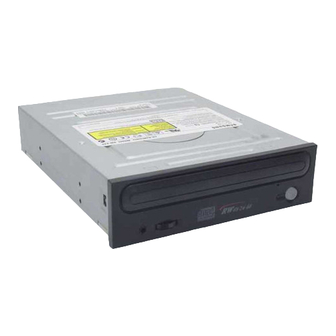
CD-R/RW DRIVE
SW-248B
Manual
CONTENTS
• Necessary equipments and Specifications in needing
Service(P/U replacement)
• Exploded Views & Part List
• Packing Options
• Main Components Block Diagram & Pin Descriptions
• Electrical Parts List
Advertisement

Related Manuals for Samsung SW-248B


Summary of Contents for Samsung SW-248B
-
Page 1: Table Of Contents
CD-R/RW DRIVE SW-248B SERVICE Manual CONTENTS • Specifications • Cautions at Service • External Part Name • Necessary equipments and Specifications in needing Service(P/U replacement) • Exploded Views & Part List • Packing Options • Block Diagram • Troubleshooting • Circuit Diagram •... -
Page 2: Specifications
Specifications 1. General Specifications Resd(MAX) : 2,000~6,000KBytes/Sec(CAV 40X) - Drive type : Computer built-in - Access time : 110ms (Random. TYPICAL) - Power consumption : DC +5V, 1.5A - Buffer Capacity : 8Mbyte DC +12V, 1.5A - Error ratio : Mode 1: Below 10 - Dimensions : 146mm (W)X42mm (H)X184mm (L) Mode 2: Below 10 - Net Weight : 750g... -
Page 3: Safety Instructions
Electricity sensing device Some semiconductor units may be damaged easily by 4) Make use of only anti-static soldering release unit. electricity. A soldering release unit not to be classified as These elements are called as electricity sensing antistatic may generate the enough charge to damage device(ESD) in general. -
Page 4: External Part Name
External Part Name 1. Front Up/Down Emergency Stop/Open Volume HOLE button Earphhone jack Disc tray 2. Rear Sound output terminal Digital Master/Slave Interface Power terminal select pin terminal output terminal (Optional) - Page 5 Disassembly Diagram...
- Page 6 Device Part List PART NAME CODE No SPECFICATION ASSY DECK BG97-02248A BG60-00009A 1.SCREW TITE M1.7*5(10) LOADING BG97-02250A 1.ASSY LOADING BG61-00203A 1.MAIN FRAME HIPS(HG1760S) BG66-00061A 2.GEAR TRAY POM(F20-03) BG66-00032A 3.GEAR PULLEY POM(F20-03) BG66-00044A 4.BELT PULLEY CR-70(BLK 1.3t) BG97-00789A 5.ASSY LOADING M/T BG31-00027A - LOADING MOTOR RF-300CH-11440 ¿Ü...
- Page 7 Disassembly and assembly Exterior and PCB disassembly Door-tray 1) Supply power to open the tray¶Êin direction of arrow “A” 2) Lift up the door¶Â in direction of arrow “B” 3) Close the tray¶Êand power off. Reference : If the tray¶Êdoesn't open, push the clip3 into specified hole shown in detailed figure to open it compulsorily.
- Page 8 Disassembly and assembly Exterior and PCB disassembly Panel-front 1) Remove 6 hooks¶Â 2) Take out the panel-front¶Êforward. Figure - Panel-front...
- Page 9 Disassembly and assembly Exterior and PCB disassembly Top-cabinet 1) Remove 4screws¶Â in the bottom 2) Lift up the top-cabinet ¶Ê Figure - Top-cabinet...
- Page 10 Disassembly and assembly Exterior and PCB disassembly Ass'y-frame Low 1) Lift up the ass’y frame¶Ê low Figure - Ass'y-frame Low...
- Page 11 Disassembly and assembly Exterior and PCB disassembly MAIN-PCB 1) Disassemble the PICK-UP FPC¶Â in PCB. 2) Disassemble the FFC¶Êbetween Main PCB and Front PCB. 3) Disassemble the FFC¶Ábetween Main PCB and Front PCB. 4) Push 2hooks¶Ëfor PCB fixing in deck. ¶È...
- Page 12 Disassembly and assembly Deck disassembly Tray 1) Push 2hooks¶Â. 2) Take out the Tray¶Êin direction of arrow. Figure - Tray...
- Page 13 Disassembly and assembly Deck disassembly Ass’y-Deck 1) Move the slide cam¶Â in left direction. 2) Remove screws¶Ê. 3) Disassemble the Ass’y-feeding ¶Áin arrow “B” direction with pushing the 2hooks in direction of arrow “A” Figure - Ass’y-Deck...
- Page 14 Packing Diagram and Part List CODE-NO DESCRIPTION SPECIFICATION Q’TY BG69-00146A MASTER CATON-BOX DM 3 1/8EA BG69-00147A PACKING-CASE SW-224B/DOM SW-1 MANILA 240g BG69-00034A CUSHION-SET BG69-30305A BAG-PE T0.05 BG46-00024A S-W UTILITY BG68-00352A MANUAL USERS BG95-50004A ASSY-SCREW BG60-12001H SCREW-MACHINE M3 * 6 ASS’Y BG39-30002A BAG-PE BG39-00010A...
-
Page 15: Block Diagram
Block Diagram... -
Page 16: Troubleshooting
Trouble Shooting Check the power source and initial state. Is electrity of 5V and 12V normally input Check the connection of the after the connecting the power cable ? power short and cable. If the power of RL3E804, RL5E935 is normal when you check, Do RL3E804, RL5E935 oscillate ? replace X201, X301. - Page 17 FOCUS UP / DOWN ? Refer to ‘ FOCUS LOCK ’ FOCUS LOCK ? DISC rotation ? Refer to ‘ NO DISC ROTATION ’ SPINDLE LOCK ? AUDIO OUTPUT ? Refer to ‘ NO AUDIO OUTPUT ’ WRITING Normall ? Refer to ‘...
- Page 18 No SLED OPERATION When you transfer the pick-up to the outer SLED operation of normal. cycle and turn the power on, dose the pick-up move to the inner one ? The below waveform is outputted in If the constant of IC301 and GND, pattern’s IC301 1, 99pin ? when you check, replace.
- Page 19 No Tray open / close operation Is the connector properly Try the operation after inserting the inserted into CN30 ? connector to CN3 properly. When pressing the EJECT SW, Check the SW701 patterns and the does the peak value of the welding condition.Replace it if the IC301 3Pin become 3.3V? condition is normal.
- Page 20 No LASER DIODE ON Is the connector inserted normally Try again after a normal insertion of the into the CN10? connector into CN10. Isn’t there any problem Try again after replace of FPC Wire. with the FPC Wire ? When the SLED is moved to the If the pattern of IC101 and sodering is inner circle, is electricity of about 1.65V normal when you checked, replace IC301.
- Page 21 No FOCUS LOCK FOCUS UP / DOWN ? Dose the S-curve below come out of the If the power of IC101 and GND, soldering The below waveform(CH B) is 76(TP:FE)pin of IC101after insertion of a disc ? is normal when you check, replace IC101. outputted in IC201 132pin ? If the power of IC201 and GND, soldering is normal when you check, replace IC401.
- Page 22 No SPINDLE MOTOR ROTATION If the power of IC201 and pattern’s, Is the waveform below output soldering is normal when you check, through 140pin of IC201 ? replace IC201. If the power of IC401 and pattern’s, Is the waveform above input soldering is normal when you check, through 24pin of IC401 ? replace IC401.
- Page 23 No AUDIO OUTPUT Replay of AUDIO after insertion of AUDIO DISC ? Is the audio output from the If the power of IC401, GND, soldering is 164, 167pin of IC201 ? normal when you check, replace IC200. Is the audio output from the Check the connection of the CN30 is and 11, 13pin of CN30 ? normal when you checked, replace VR701.
- Page 24 No WRITING Can WLT216B.EXE be Replace P/UP or the entire MECHA. executed properly? Was the Power Calibration executed properly? When you try to write the records again,does it work properly? Check the condition of the When writing the records,does the power at CN10, voltage at the PIN 20 (XWGATE) GND and the welded part.
-
Page 25: Circuit Diagram
Circuit Diagram Main... - Page 26 Circuit Diagram Front...