HP 54501A Operation Reference
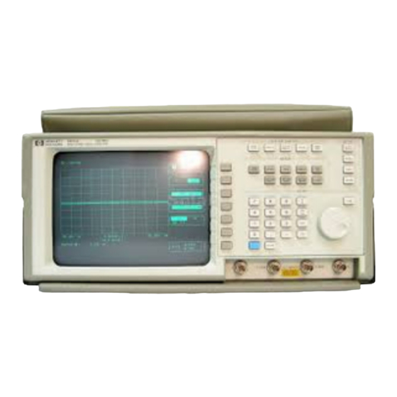
Front panel operation reference
digitizing oscilloscope
Hide thumbs
Also See for 54501A:
- Programming reference manual (386 pages) ,
- Service manual (90 pages) ,
- Getting started manual (46 pages)
Table of Contents
Advertisement
Quick Links
Advertisement
Table of Contents

Related Manuals for HP 54501A


Summary of Contents for HP 54501A
- Page 7 Front Panel Operation Reference HP 54501 A Digitizing Oscilloscope PACKARD Valuetronics International, Inc. 1··800-552-8258 MASrEI� COPY yrigh t Hewlett-Packard Company 1988 Publication 54501-90901 Printed the U.sA. August 1988...
- Page 9 Product This Hewlett-Packard product has a warranty against defects in material and workmanship for a period of three years from date of shipment. Warranty During warranty period, Hewlett -Packard Company will, at its option, either repair or replace products that prove to be defective. For warranty service or repair, this product must be returned to a service facility designated by Hewlett-Packard.
- Page 10 Exclusive Remedies THE REMEDIES PROVIDED HEREIN ARE THE BUYER'S SOLE AND EXCLUSIVE REMEDIES. HEWLETI·PACKARD SHALL NOT BE LIABLE FOR ANY DIRECT, INDIRECT, SPECIAL INCIDENTAL, OR CONSEQUENTIAL DAMAGES, WHETHER BASED ON CONTRACT, TORT, OR ANY OTHER LEGAL THEORY. Assistance Product maintenance agreements and other customer assistance agreements are available for Hewlett·Packard products.
-
Page 11: Table Of Contents
Table of Contents Chapter 1: Introducing the HP 54501A Introduction Chapter 2: Instrument Setup Introduction Unpacking Contents of Shipment Initial Inspection List of Accessories Operating Environment Storage and Shipping Rear Panel Layout 2- 3 Power Requirements 2- 3 Applying Power... - Page 12 Chapter 3: Front Panel Overview Introduction to the Front Panel System Control RUN/STOP Key SINGLE Key CLEAR DISPLAY Key LOCAL Key HARDCOPY Key Setup AUTOSCALE Key RECALL Key SAVE Key SHOW Key Menus 3- 8 Entry Numeric Keypad Knob FINE Key Input 3-10 Display...
- Page 13 Chapter 5: Channel Menu 5·1 Introduction to Channels 5·1 CHANNE L Key 5·2 Vertical Sensitivity Key 5·2 offset Key 5·3 coupling Key 5· 3 more Key probe Key ECLKey TIL Key Chapter 6: Trigger Menu 6·1 Introduction to the Triggers Trigger Mode Interaction Edge Trigger Mode Trig'diauto Key...
- Page 14 6-16 Instrument Setup 6-17 Oscilloscope Setup 6-20 Delay Trigger Mode 6-20 qualify on Key 6-20 edge Qualify Option 6-21 pattern Qualify Option state Qualify Option 6-21 6-22 delay Key 6-22 trigger on Key 6-23 Delay Trigger Exercise 6-23 Instrument Setup 6-23 Oscilloscope Setup 6-27...
- Page 15 Chapter 8: Delta !/Delta Menu lntroduction to the Markers DV markers Vmarker 2 Vmarker 1 markers start marker stop marker Chapter 9: Waveform Math Menu 9- 1 lntroduction to the Functions Defining a Function Function Key display Key chan!mem Key Operator Key chan/mem Key sensitivity Key...
- Page 16 Chapter 10: Waveform Save Menu 10-1 Introduction to the Memories 10-1 waveform/pixel Key 10-2 waveform Menu nonvolatile Key 10-2 10-2 display Key 10-2 source Key 10-2 store Key 10-3 pixel Menu 10-3 volatile Key 10-3 display Key 10 -3 clear memory Key 10-3 add to memory Key 10-4...
- Page 17 Chapter 12: Utility Menu 12-1 Introduction to the Utilities 12-2 HP-IB menu 12-2 talk only mode 12-2 addressed mode 12-3 EOI Key 12-3 form feed Key 12-3 paper length Key 12 -3 exit menu Key 12-4 selftest menu 12-5 ram Test...
- Page 18 Appendix A: Algorithms Measurement Setup Making Measurements Automatic Top-Base Edge Definition Algorithm Definitions delay + width -width Period A -5 Frequency Duty Cycle Risetime Fall ti me A -5 Vmax V min V p-p A -6 Vtop A -6 V base V a mp V a vg V rms...
-
Page 19: Introducing The Hp 54501A
Introducing the HP 54501A Introduction The HP 5450lA is a general purpose, digitizing oscilloscope that is fully It is programmable and transportable. an excellent general purpose digitizing oscilloscope because of the friendly user interface, yet it has sophisticated capabilities and multiple triggering many functions. -
Page 21: Unpacking
Introduction This chapter contains information regarding instrument operation. By the time you finish reading this chapter you will have the HP 5450lA unpacked, plugged in, hooked up and ready for operation. It is important to follow the instructions carefully. A great deal of information is covered that will maximize the performance and effectiveness of the HP 5450lA. -
Page 22: List Of Accessories
Probe Socket, part number 1250-1737 • Mini PC Board Vertical· Probe Socket, HP part number 1250-1918 Operating You may operate your 5450lA oscilloscope in a normal lab orbench environment without any additional considerations. Pay special attention Environment to the non-condensing humidity limitation. Condensation instrument cabinet cause poor operation or malfunction. -
Page 23: Rear Panel Layout
66 Hz; 200 Watts maximum power. to + 10%; single phase, a power-up self test will be Applying Power Wben power is applied to the HP 5450lA, performed automatically. For more information conerning the test, Chapter 12. Voltage Selector and... - Page 24 CAB'" LENGTH PLUG DESCRIPTION COUNTRY PLUG TYPE COLOR PA.RT NO. INJC>! 01'7 Gf·Y I)nll eo KinpoDm. -� Staigtl! "8513$3.A Mrl'l\ 612Q.13S1 "-,L 11I2().1703 "" Of'Y C",M ZimDallwC' .." 8120-1369 Slfllglll 'NZSSI981A$C 0." ,l,uArllla.. """ """ 811221 Mini GrlY New ZeaI.nO "...
-
Page 25: Installing The Power Cord
The HP 5450lA is a Safety Class 1 instrument (equipped with an exposed Installing the Power metal chassis that is directly connected to earth via the power supply Cord cord) that meets IEC Standard 348. The line voltage selector has been factory set to the line voltage used in Selecting Une Voltage your country. -
Page 26: Checking For The Correct Fuse
Checking for the If you fInd it necessary to cbeck or cbange fuses, remove tbe fuse module and look at each fuse for its amperage and voltage ratings. Correct Fuse 3.0 A FUSE FUSE Figure 2-4. Checking/or the Corr e ct Fuse Line Switch Tbe line switcb is located on the rear panel. -
Page 27: Intensity Control
Intensity Control Once the oscilloscope has been turned on, you may want to set the display intensity to a more comfortable setting. Adjust the intensity by turning the DISPLAY IN1ENSITY control the rear panel. Figure 2-6. Intensity Control You must provide an unrestricted airflow for the fan and ventilation Air Flow over, Requirements... -
Page 28: Connecting External Equipment
Connecting is equipped with an connector on the rear panel. HP-IB 5450lA This allows a direct connection to a printer or an external controller. External Equipment Connect an cable to the osciJJ o scope and a desired device (as HP-IB shown). -
Page 29: Front Panel Overview
Front Panel Overview I ntroduction to This chapter describes the functional sections of the HP front 5450lA panel. The explanation of each area also contains their interaction with the Front Panel each other and provide a basis for applications and usages. -
Page 30: System Control
System Control Section The Run/Stop key is RUN/STOP Key toggle switch that changes the acquisition status of the HP 5450lA. If the oscilloscope is currently running (current status is in the top corner of the CRT in the message field) the displayed... -
Page 31: Single Key
You can manipulate acquisitions with these three keys and not affect other keys and settings. LOCAL Key The Local key will send a return to local control message to the HP·m This interface and return control to the front panel. -
Page 32: Setup
Setup The Setup section of the front panel contains keys to control subsystems for proper display of input data. In this section you can control: • AUTOSCALE for automatic scaling of the waveform display area • Save and Recall setups •... -
Page 33: Autoscale Key
ECurTL presets. RECALL undo of these actions. You cannot save to RECALLO. • CLEAR RECALL executes an instrument reset and returns the HP 5450lA to default/power-up settings. The oscilloscope does not perform power-up self-tests (see Instrument Reset). Front Panel Interface... -
Page 34: Save Key
SAVE Key The SA YE key will immediately store the oscilloscope setup configuration in volatile memory. If you press SA YE, you must then select a save 3, or register: 1, 2, 4. An advisory will be displayed above the waveform display area indicating the setup configuration has been saved. -
Page 35: Menus
Menus The Menus section consists of nine keys to select from: • Timebase • Channel • Trigger • Display • 1:J. t/I:J. V • Waveform Math • Waveform Save • Defme Measure • Utilities One of these menus is discussed in each of the following chapters. ODDOCl DODO OODO... -
Page 36: Entry
Entry The Entry device section contains a multi-function numeric keypad, a selection knob, and a fme key. DODO � DODO 8888 DODO " I1 " ��»'fU': r"u.tlfll: P1:RlOO RISElIl£ nU-AY -rOl", -' 0'" DIJrY cv ,� CD CD 0 , �E ,�... -
Page 37: Fine Key
To the right of the number keys is a vertical column of keys witb measurement units. The bottom row of keys contains a blue (Shift) key to select alternate keys that are labelled in blue and a CLEAR key to clear any selections made. -
Page 38: Display
Display The Display section contains the screen and selection keys. In a vertical column on the right side of the screen is the function display. The functions that are displayed at anyone time will correspond to a key in the selection column. These keys can select any available function or field that is displayed in halfbright. -
Page 39: Instrument Reset
Instrument 54 5 0lA has two methods used for instrument reset. Reset • Key-down power up is a hard reset of the oscilloscope. It is done by pressing and holding any front panel key while cycling power. If no input signals are present, the oscilloscope will power-up displaying a no signal is present) and the SHOW screen and set with baseline all default settings (see Table... - Page 40 Table 3-1. Reset Default Conditions (continued) Trigger Menu Mode edge source Channel 1 level Q.O V slope positive holdoff 40ns Display Menu Mode norm mID1rnum persistence of screens off/frame/axes/grid axes connect dots L>.t/ L>. V Menu L>.t markers L>. V markers Waveform Math Menu chan/mem chan1...
-
Page 41: Timebase Menn
Timebase Men u I ntroduction to This chapter contains a complete description of h w the Timebase menu works and controls the entire horizontal display and parameters. Each the Timebase function key will b e described in detail. TlME8ASE delay reference left center... -
Page 42: Delay Key
At these sweep speeds the oscilloscope needs up acquisition, seconds to generate a trigger and tberefore, the displayed data updated for each data sample. The HP 5450lA must accommodate two trigger conditions for acquisition and display: •... -
Page 43: Reference Key
reference Key The Reference key changes the delay reference point to one of the following: • left • cntr (center) • right If delay is set to 0, the reference point consists of pre-trigger data to the left and post-trigger data to the right. window Key With the \Vindow function turned on an expanded tirnebase is activated and the oscilloscope is placed in a multiple screen mode. -
Page 44: Timebase Key
When the reference position is set to left, only the right window marker moves when the window limebase is changed. When reference is set to right, only the left marker moves, and when cenler is selected, both markers move. This maintains a specified time reference without changing any timebase settings and yet you have the ability to move the reference points for better viewing. -
Page 45: Window Exercise
Set DTY • Set OFS -1.20 • Set signal to squarewave IIlput this signal to channel Setting the on the HP 5450lA and disconnect any inputs Oscilloscope to any other channel. • AllTOSCALE Press (see FIgure 4-2). IIp runninQ zoo ",V/di"... -
Page 46: Viewing The Window
• Press tbeTimebase menu key. • Press the selection key to turn on tbe window function. • Set the window timebase to 40 I'o8Idiv (see Figure 4-3). u nn T1ME:BASE i ng r.delOY 0 00000 reference w i n dow t imebase posit;oo 0.00000... - Page 47 • will delay, as you turn the knob the wmdow and waveform move sideways and maintain the same size. This allows you to view the same section of the waveform at a different point in time. The two timebases will not change. •...
-
Page 49: Channel Menu
Channel Menu Introduction to The channel menu allows you control the vertical operation of the HP 5450lA. This chapter describes the use of the four channels, including Channels vertical sensitivity, offset, coupling, attenuation and preset levels that are available. C�ANNEL El �... -
Page 50: 5·2 Vertical Sensitivity Key
· selected either of the entry devices be used for data entry. The range of the vertical sensitivity for the HP 5450lA is from 5 mY/division to 5 V/division. Vertical sensitivity changes in 1-2-5 sequence in the normal mode or can be changed in the f me mode. -
Page 51: More Key
cou pling Key The coupling key has several selection variables. They are as follows: • • ac bandwidth limit • • de bandwidth limit � MHz. It Bandwidth limit reduces the effective bandwidth to reduces the noise in the display path as well as the trigger path. more Key Pressing the more key allows you to toggle between the two channel menus. -
Page 52: Probe Key
probe Key Using the probe key enables you to select probe attenuation with a range of 1000:1 down to 0.9000 : 1. To adjust the attenuation you use either the knob the entry keypad. When using the knob, and in the coarse mode, the adjustments will increment or decrement in the familiar 1·2·5 the f me mode the changes will be 0.1. - Page 53 TTL Key . The TTL key allows you to set the oscillosocpe with levels that are optimized for TTL circuits. They are: • VIDiv: 1 V/div • offset: 2.5 V • coupling: de • Trigger level: 1.4 V • Trigger slope: no change To return to the previous settings press RECALL O.
-
Page 55: Trigger Menu
Trigger Menu Introduction to HP 5450lA has five triggering modes available. These modes make available many distinctive techniques to trigger and capture data. Its the Triggers capabilities range from simple edge triggering to logic triggering on multiple signals. This chapter contains a complete description of the triggering modes, as... -
Page 56: Edge Trigger Mode
following Edge Trigger In the edge trigger mode you make the selections: Mode • trig'dlauto • trigger source • trigger level • slope • holdoff TRIG MENU EDGE TRIGGER t r i g ' d/outo s o u r ce leve l ho l do f f Figure 6-1. -
Page 57: Source Key
Trig'd/auto Key The trig'dlauto selection is a toggle selection and lets you select hetween the two. The current selection is displayed in inverse video. This field is available in all trigger modes. EDGE TRIGGER tr ig'd Mouto' When in the triggered mode the oscilloscope will not acquire data until all state delay of the trigger requirements have been satisfied. -
Page 58: Holdoff Exercise
Use an Pulse/Function Generator with the burst option or HP 8116A a signal generator capable of the same signal, Make the following settings: • MODE: I.BUR •... - Page 59 200 mV/d i v o f f s e t : -225 . 0 1 . 000: ; . . ." . . .:� " t·; · · " 5 . 00000 u s 0 .
- Page 60 Press the key. Set holdoff to 1.02000 IJ.S, using either of the entry devices. • Holdoff on the HP 5450lA has a minimum setting of 40 Th."input signal to the oscilloscope has two 500 pulses. On the first rising edge a occur s and activates the 40 ns holdoff.
-
Page 62: 6·8 Pattern Trigger Mode
The pattern mode allows you to define a four character pattern that the oscilloscope will recognize and generate a trigger event. When the inputs Mode satisfy the trigger pattern and conditions the HP 5450lA will trigger and PATTERN TRIGGER display the desired portion of the waveform. -
Page 63: Pattern Key
pattern Key This is an unlabelled field. The display depicts the four-bit pattern. The active field is displayed in fullbright and be changed using the knob. The selection key changes the bit selection. The available selections are: • H - high •... - Page 64 These trigger levels must be set before you go 10 the pattern mode, or proper triggering may nol occur. To perform the following exercise use the PulseIFunction Instrument Setup HP 8116A Generator, or another function generator capable of producing the same volt, squarewave signal. 1 MHz, 1 Trigger Menu...
- Page 65 Set up the HP 8116A Pulse/FUnction Generator: • Mode NORM • 1.00 • • 1.00 V • -2.00 V • Pulse ;;;: : squarewave Connect the signal to a BNC tee on channel 1 using a 1 meter coaxial cable. Connect another 1 meter cable from the other side of the BNC tee to channel 4.
- Page 66 • until entered Press the when key is selected. The display should be similar to the following figure. hp runn i ng PATTERN TRIGGER tr i g ' ti edge 'pot tern' state cie l o tv when -50. 000 os 0 .
- Page 67 -200 m V and channel 4 is still low (less than -200 m V) the pattern conditions have been satisfied the signal is entering the trigger conditions and the HP 5450lA triggers. • Press the when key and change the condition to when exited.
- Page 68 Change the trigger condition to when exited. While ehanne1 4 is still high, when ehannel l goes low the bit pattern longer true and the HP 5450lA triggers. P" TTERN TRIGGER " , , " hp runn i n g 0 .
-
Page 69: When Key
Mode 5450lA defme a pattern. When the pattern becomes true the HP triggers on the next clock edge if the�pattern meets setup and hold criteria. STATE TRiGGER trig'd .auto.]... -
Page 70: Present Key
The state trigger mode enables you to see only those events that occur when reading from a block of memory. Instrument Setup To perform the following exercise use an HP 8116A Pnlse/Signal generator or another signal generator capable of the same MHz, volt squarewave. -
Page 71: Oscilloscope Setup
Set up the HP 8116A as follows: • Mode NORM • 1.00 MHz • • LOO V • -200 Connect the signal to a BN C tee on channel using a meter coaxial cable. Connect another meter cable from the other side of the BNC tee... - Page 72 XXL pattern • Press the when key until is present is selected (see Figure 6-11). SlATE TRIGCER hp r u n n i n g t r i g ' d tern when '- present 50.CX>O 1'15 0 . 00000 :so .
- Page 73 • and select the is not present Change the bit pattern to condition. STATE TRIGGER hp r u n n i n g t r i g ' d . ® � 0 . 00000 \'l s / d i 10.0...
-
Page 74: Delay Trigger Mode
Delay Trigger The Delay Trigger mode allows you to qualify on a signal edge, pattern, or state, delay for a period of time (or occurrence of edges), and then trigger Mode on a selected edge from any source. DELAY TRIGGER tr i g ' d .cu to. -
Page 75: Pattern Qualify Option
pattern Qualify Option When the pattern trigger option selected, the next selection key allows you to define the qualifier pattern. Defining a pattern the same in the Pattern Trigger mode. • Highlight the bit to be changed by pressing the selection key. •... -
Page 76: Delay Key
DELAY TRIGGER count from 1 to 16,000 , 000 after the trigger has been qualified. After the selected count has been attained the HP 5450lA will look for the user a u l o specified trigg e r edge. -
Page 77: Trigger On Key
trigger on Key This key allows you to select a specific edge to trigger on after the qualification and delay conditions have been satisfied. other keys in this this menu have dealt with defining qualifying conditions, however, field allows you to set the trigger point. This is another three position option switch. -
Page 78: Oscilloscope Setup
• Press AUTOSCALE. hp r u nn i n g 200 mV/d i v o f f s e t : -225 , Q mY 1 . 00 0 : '., , '... - Page 79 T IMEBASE runn i n g t · t -. left cntr r 1 9htJ , r-I�;�i-:-�� l ' . " .: 0 , .: " .: 0 • • , . :" " . . " .:" :" 2 , 50000 0.
- Page 80 • Change the tri8!!'" on count key to (see Figure 6-16). 1"19 DELAY TRIGGER r unn i q ' d a u t o e d g e pa t t e r n , oll o l pot t e r n s t ate .
-
Page 81: Tv Trigger Mode
Trigger Trigger menu enables the HP 5450lA to trigger on clamped signals. The two most common standards; Hz/525 lines or NTSC Mode the standard used in the United States, 50 Hzl625 lines the standard used in most European countries. This trigger menu also allows for user defined signals that may be used in other parts of the world. -
Page 82: Field Key
level/polarity Key The level option allows you to set the trigger level that is applicable only to source. trigger • Press the selection key again and the highlighted window moves to the polarity option and allows you to select the rising edge or falling syoc pulses to trigger on. -
Page 83: Tv Trigger Exercise
Use a standard NTSC signal generator with clamped video output for this Instrument Setup exercise. color bars on. Oscilloscope Setup 5450lA. Connect the NTSC video signal to channel 1 of the HP • Press AUTOSCALE. • Select the trigger mode. - Page 84 Press DISPLAY and set persistence to 600 . 0 to accommodate video signals. TV TRIGGER hp r u n n i ng auto e dge p a t t e r n s t a t e de l ay n �...
- Page 85 Tv TR1GGER nmn i ng (luto edge s t o t e Hz/525 so urc __ AU - - - - - - - - 50. 0000 0 . 000 0 0 -50. 000Cl us 10,0 us/d i v time i.ne Figure frI8.
- Page 86 The trigger point now on the last sync pulse of the vertical interval. The case this next line contains colar information, in color bars are present. • Change the trigger to field line TV TRIGGER i ng auto po L t e r n edge s t o t e de l ay 50 Hzl525...
-
Page 87: Introduction To The Display
Display Menu Introduction to The Display menu controls most of the features that dictate how the acquired data is displayed. These features include ways to manipulate the Display case data for clarity, to eliminate noise, viewing best case/worst situations, o r the displayed background. This chapter describes the Display menu, three submenus, how to control the features, and how to display the most meaningful waveform for your measurements. -
Page 88: Display Mode Key
Infinite persistence be used for worst characterizations of drift, etc. In this mode the used signal'noise, jilter, HP 5450lA as a storage oscilloscope. you use the keypad to change persistence settings, any entry longer than range, set to limit... -
Page 89: Avg
When norm has been selected, the selection key beneath the norm field is This activated. field displays the current persistence setting and can be set using either of the entry devices. Connect the dots only available when in norm mode and mjnimum persistence. The averaged mode allows you to select the number of waveform acquistions that are averaged to generate the displayed waveform. -
Page 90: Of Screens Key
# of screens The next selection key allows you to choose the number of screens you wish to view. The selections are: • 1: the entire display area is one screen and any displayed waveforms are superimposed on top of each other. •... -
Page 91: Off/Frame/ Axes/Grid Key
Channel Channel 2 Channel Channel 545011WF5€ Figure 7-3. Quad Screen Dis play off/frame/ This .is an unlabelled field that is used to select the display background. Four options are available: axes/grid Key • off: Tbe off option turns the background gratieule off. Tbe displayed waveform and waveform information is not turned off. - Page 92 Note Connect the dots doe s not intepolate data and generate data points. The HP 5450lA connects data points linearally. DISPl AY hp r u n n i ng pers i s ience Q v g s;reen: l...
-
Page 93: Lntroduction To The Markers
Delta t/Delta V Menu Introduction to This chapter describes how to use the markers and make manual measurements on displayed waveforms. the Markers In this menu you have control of tW o sets of markers. These markers give you manual control of the V markers (horizontal voltage markers) and the Ilt markers (vertical time markers). -
Page 94: Vmarker 2
t.V markers selection key toggles the markers on and off. With the t. V function This turned on the next two fields are activated allowing you to control the two markers individually. When the V markers are turned on, and de/ta V marker2, V markerl, appears in the factors display arca. -
Page 95: Stop Marker
.6.t markers This selection key toggles the time markers on and off. With the .6.t function turned on the next two fields are activated allowing you to control the two markers individually r1::N � ma r k e r s The markers are placed on the display respective of the trigger point. -
Page 97: Waveform Math Menu
Functions from any of the four channels or from any of the four waveform memories. function is generated by mathematically manipulating one or two operands with known operations. The mathematical operations employed by the HP 5450lA are: • plus ( + ) •... -
Page 98: Defining A Function
• evaluated with the measurement features • stored in memory • outputted over the HP-m Defining a The Waveform Math menu allows you to select and preset any of various operations, sources, and displayed results. Function r d i s p l oy... - Page 99 If the function display is turned on the screen split with the original will waveforms displayed in the top half screen while the functions are displayed in the bottom half screen. Both functions be on at the same time and they be displayed superimposed or in two screens in the will bottom half of the CRT if multiple screens have been selected.
-
Page 100: Sensitivity Key
+ 2V signal to ehannel l and a -3V signal ehannel displays the product as -QV, when in reality it _6V2. 2. The HP 5450lA Displaying has several screen variations available to accommodate a HP 5450lA ehannel display, as well as two functions. The display may seem Functions confusing until you understand how the separate screens are displayed. - Page 101 Area Channel 1, 2, 3, Viewing Area function 1, 2 Viewing Figure 9-2. Single Screen wlFunction On • In the dual screen mode the functions are again displayed in the bottom half of the screen, however, the dual screens are displayed in the top half.
- Page 102 • In the quad screen mode, all four screens are displayed in the top half of the display while the functions are displayed in the bottom half. Channel ! Channel 2 Channel 3 � function Figure 9-4. Quad Screen wlFunction On Waveform Math Menu...
-
Page 103: Waveform Math Exercise
Waveform Math In this exercise you will use the Waveform Math menu to subtract one waveform from another. Exercise Set up an HP 8116A, or a signal generator capable of a 1 MHz, Instrument Setup volt squarewave, follows: • MODE NORM •... - Page 104 Now you see the function of subtracting channel from channel The propagation between channels has allowed a spike. To better view the results: • Press and set the horizontal display to 50.0 (see TIMEBASE nsidiv Figure 9-5). ehon[jJ 2 chon 1 3 [3] ns/d i 9-S.
-
Page 105: Introduction To The Memories
Waveform Save Menu I ntroduction to chapter describes how to select the waveform and pixel memories on This 5450lA. The menu consists of two submenus: the Memories • waveform memories mI - m4 used to store one waveform at a time. •... -
Page 106: Waveform Menu
Voltage and time markers can be set on waveforms when they are displayed. ,- source chonm 2 3 4 When the HP is in the envelope display mode and a waveform 5450lA f u n c store is executed, the value and max value are stored separately. -
Page 107: Pixel Menu
pixel Menu The pixel submenu allows you to select the pixel memories. These memories are very useful when you need additive memory capabilities. Waveforms be stored and added to indefInitely. WAVEFORM SAVE c l ea r memory t o memor y s..t 50 1 I'1'1f l S volatile Key This... -
Page 108: Waveform Save Exercise
This waveform, change the offset setting, and recall the stored waveform to be compared with the current Exercise display. HP 8116A 6 kHz, 1 Instrument Setup Set up an or a signal generator capable of a volt squarewave: •... - Page 109 This will move the current display so you view the stored waveform. The display should look like the following fignre. WAVEFORM SAVE hp r u nn i n g ml m2 13 m4 o f f store 545011WF43 250 , 000 us -250.
-
Page 111: Define Measure Menu
Define M easure Menu . Introduction to This chapter contains a description of how to use the measurement menu. This is a very powerful and encompassing feature. By pressing the front Measurements panel button access the entire measurement function. Define Meas U Ine 0 1 I u .. -
Page 112: Measurement Selection
The first menu allows you to set the dynamic controls for your measurement. The second allows you to set user-defined parameters for your measurements. And the third allows you to set up the measurement comparison test. Measurement It is very simple to make measurements from the keyboard. Each key in the numeric keypad section has a secondary function, Above each key Selection measurement selection printed in blue. -
Page 113: Meas/Meas Def/Meas Limit Key
meas/meas This key is the primary sub-menu selection key. Press to select one of the available sub-menus. This field will always be the top selection so you can def/meas limit select other sub"menus at any time. meas Sub-menu The measure sub-menu is the default condition. You can access the continuous and statistics options. -
Page 114: Measure Define Sub-Menu
This gives you the option of making Sub-menu measurements based on signal width delay settings or threshold parameters. standard is selected, no other choices are available and the HP 5450lA standard/user defined make measurements based on the IEEE standards for your particular will measurement. DEFINE MEAS... - Page 115 Note I f the user defined upper and lower thresholds are placed too is possible the H P 54501A will not be able to close together determine the mid-point. The message 'not found' will be displayed in the measurementf actors area.
- Page 116 • When setting edge count fields, it is handy to press the f me key. HP 5450lA the course mode the increments/decrements by tens 11, 21, ... 100). In the f m e mode the increment/decrement sequence in l's.
-
Page 117: Measure Limit Sub-Menu
Measure Limit 5450lA run limit tests on on up to three measurements. The menu allows you to preset certain conditions and store any fallure data for Sub-menu evaluation at a later time. You set your limit test while in this menu and select your measurement from the front panel. -
Page 118: Key
set Key This allows you to select the measurement. You have sixteen measurements available; the same ones as are available on the numeric keypad. • Press the selection key to highlight the field and rotate the knob to select the desired measurement. >... -
Page 119: Utility Menu
Utility Menu Introduction to The Utility Menu is used access the calibration and service functions, well sel up the HP·m inlerface. The submenus include the Utilities self·lest, calibration, printer hook·up and a listing for the current firmware revision date. UTILITY HP-IS... -
Page 120: Talk Only Mode
HP-IS menu 5450lA The HP-m submenu allows you to make settings so the HP talk to peripheral devices. This interface includes two primary settings: HP-IS • talk only mode • addressed mode UTIlITY HP-IS menu toll<. on l y 1 2 ; n �... -
Page 121: Eoi Key
Note IEEE 488. 2 requires that is asserted. Therefore, with will IEEE o ff, the HP 5450lA send messages that do not follow E01. EO! 488 . 2 rules concerning should only be turned off wi th EOl your controller does not deal appropriately. -
Page 122: Selftest Menu
HP 5450lA has been designed to perform internal diagnostics. This selitest submenu allows you to test the oscilloscope to determine r om potential cali b ration errors. SELFTEST IA£NV EEl! loOP mi s e HP 5450lA fails any selitest perform the following:... -
Page 123: Rom Test
5450lA self-diagnostics and self-tests are designed to operational tests on the following: • • • acquisition • miscellaneous ram Test The ram test is a multiple selection field. The options are: • display • acquisition • system • unprotected nonvolatile memory rom Test Two rom tests are available: •... -
Page 124: Acquisition Test
• • timebase • Miscellaneous Test Three miscellaneous tests are available: • HP-m • keyboard • loop Test The loop test a function designed for use by qualified service nnnecessary to use this function for normal personnel. - Page 125 probe cal menu Two probe calibration procedures are available in the probe ca1 menu. They are: • attenuation • time null UTILITY attenua t i on t i me n u t 1 -7 4 to 2 -? 4 1 -70nll -1>- 70n$ Figure 12-5.
-
Page 126: Attenuation Submenu
The attenuation submenu is used to calibrate channel gain at the probe attenuation submenu tip. Channel gain be corrected through probe attenuation down to PROBE CAL tJ.ENU attenuation. o t ti!:nuo t i on t. i me n\J f l •... -
Page 127: Time Null Submenu
time null submenu Time null allows you to set the timing of all channels to correspond to This each other. eliminates any time discrepancies between channels and guarantees that channel to channel skew v ariations are non-existent. This useful to manually adjust any differences in cable PROBE MENU length. - Page 128 Self Cal menu In the self menu you calibrate internal functions: • vertical • delay cal SELf CAl MENU _ . _ • • • s e l ec t PROTECTED SYSTEM CAL c o l ehonne de l a y s t a r t ca l con t i nue...
-
Page 129: Continue Key
The service menu is used primarily for software settings and hardware adjustments. These are to be used by qualified service personnel. 5450lA One cali b ration needed for the software calibration of the HP is in the service menu. You must set the default cah bration before ca!;... -
Page 130: Calibration Procedure
Calibration 5450lA is very simple. When you have The process to calibrate the initiated the process the oscilloscope will display instruetions for Procedure completion. Note Before the H P 5450lA can be calibrated the CAllBRATION toggle switch on the rear panel must be set to UNPROTECTED. The procedure for calibration is: •... -
Page 131: Measurement Setup
Algorithms One of the HP 5450lA's primary features is its ability to make automatic measurements on displayed waveforms. This chapter provides details on how automatic measurements are calculated and some tips on how to improve results. Measurement Measurements typically should be made at the fastest possible sweep speed for the most accurate measurement results. -
Page 132: Automatic Top-Base
Standard When any of the standard measurements are requested, the 5450lA first determines the top-base voltage levels at 1000/0-0%. From this Measurements information, it can determine thresholds (10%, 90%, and 50%) needed to make the measurements. The 10% and 90% thresholds are used in the risetime and falltime measurements. -
Page 133: Edge Definition
Edge Definition Both rising and falling edges are defined as transitional edges that must cross three thresholds. rising edge must cross the lower threshold in a positive direction (defining it as a rising edge), cross the mid threshold (any numher of crossings, both positive and negative are permissible) and then cross the upper threshold without any crossing of the lower threshold. -
Page 134: Width
f ll'St edge on minimum waveform rising then delay mid-threshold of first rising edge of max waveform minus mid-threshold of first rising edge on min ""veform else delay mid-threshold o f fi r st falling edge on min waveform minus mid-threshold of first falling edge on max waveform The standard delay measurement occurs when in the standard mode (not user-defined) and is not a... -
Page 135: Period
User-defined the same as Standard definition except user-defined threshold. - width The - width algorithm has standard and user-defined considerations: first edge is rising then -width second rising edge - first falling edge else - width first rising edge - first falling edge Period first edge is rising then... -
Page 136: Vtop
Vtop most prevale t poi t above waveform midpoint V top Vbase = Vba.. most prevale t point below waveform midpoint Vb ... Vamp V top Vamp V.vg Average voltage of the first cycle of the displayed signal is measured. If a complete cycle is not present the oscilloscope will average all data points. - Page 137 S pecifications Bandwidth (dc coupled) (ac coupled) Repetitive to 100 MHz 10 Hz to 100 MHz Single Shot 10 Hz to l MHz to l MHz (based on points per period of input signal) Risetime 3.5ns Risctime "'" O.3S/Bandwidth Number of Channels 4 (2 + 2) 2 and 3 Channels...
- Page 138 Timebase Range Minimum 2 ns/div Maximum 5 s/div Time Base Accuracy 0.005% Delta t Accuracy 1 ns ± (5E-5) Delta t ± 0.02 (tJdiv) Delta t accuracy for duaJ-cursor, single-channel measurement, or for calibration has channel·to-channel measurement after visual time null been done.
- Page 139 5 mV/div is 7 Since expansion resolution bits that rang<. (0.8%) :t: 0.1% - 10 bits via HP-m (witJi averaging) Maximum Sample Rate 10 Msals Memory Depth 501 points (display) 1024 points (via HP-m) Single Shot via HP-IB 500 points...
- Page 140 Maximum Time Base lOOps Resolution Available Delay Range Delay TIme Base Setting (post-trigger) 50 ms - 5 s (s1div) 100 j.LS j.LS ns - -10,000 (s/div) Trigger Pulse Width 7 ns (minimum) Trigger Level Range renter divisions from SpeCifications and Characteristics...
- Page 141 Index ca! select Key 12-10 L:.t/L:. V marker 3-5 Calibration Procedure 12-12 to complete 4-2 calibrator protection 2-3 + width 1-3 chanlmem Key 9-3 - width 1-4 Channe l3-7 CHANNE L Key 5-1, 12-8 - 12-10 Channel Menu 5-1 CLEAR DISPLAY Key 3-3 CLEAR key 3-9 abort Key 12-6, 12-8, 12-11 clear memory Key 10-3...
- Page 142 HARDCOPY Key 3-3 EOl Key 12-3 holdoff3-5 Exercise Holdoff Exercise 6-4 Waveform Save 10-4 holdoff Key 6-3, 6-10, 6-16, 6-28 Delay Trigg e r 6-23 HP-IB interface 3-3 Holdoff6-4 HP-IB menu 12-2 Pattern Trigger 6-10 Humidity 2-2 State Trigger 6-16...
- Page 143 Local meas/meas deflmeas limit 11-3 more 5-3 nonvolatile 10-2 of screens 7-4 offlframelaxeslgrid 7-5 CLR MEAS 11-2 offset 5-2, 9-4 continuous 11-3 operand 9·3 EOI 12·3 operator 9-3 form reed 12-3 paper length 12-3 or if 11-6 pattern 6-9 Run/Stop 3-2 position 4-4 save after 11-6 present 6-16...
- Page 144 # (number) of screens 74 numeric keypad 3-8 level Key 6-3 6-28 leveVpolarity Key 6-28 5-2, line Key offset Key Offset, hysteresis, trigg e r cal 12-10 Line Switch 2-6 line voltage selector 2-5 lJdeJta t 8-3 List of Accessories 2-2 Operating Environment 2-2 LOCAL Key 3-3 Operator Key 9-3...
- Page 145 standard - width A-4 standard/user defined Key 11-4 start ca! Key 12-8, 12-10 start marker 8-3 start test Key 12-6 ram Test 12-5 State Trigger Exercise 6-16 range 6-10 state Trigger Mode 6-15 Rear Panel Layout 2-3 statistics Key 11-3 RECALL 0 3-5 stop marker 8-3 RECALL CLEAR 3-5,...
- Page 146 6-1, 6-27 Trigger level 3-5, 6-1 Trigger Menu 6-1 6-22 trigger on Key triggered scroll 4-2 waveform math 3-5, 3-7 TTL Key 5-5 6-29 Waveform Math Exercise 9-7 Trigger Exercise Waveform Math Menu 9-1 Trigg e r Mode 6-27 waveform Menu 10-2 Waveform Save 3-7 Waveform Save Exercise 10-4 Waveform Save Menu 10-1...