Table of Contents
Advertisement
Quick Links
Advertisement
Chapters
Table of Contents

Related Manuals for Mitsubishi Electric GT16


Summary of Contents for Mitsubishi Electric GT16
-
Page 3: Safety Precautions
SAFETY PRECAUTIONS (Always read these precautions before using this equipment.) Before using this product, please read this manual and the relevant manuals introduced in this manual carefully and pay full attention to safety to handle the product correctly. The precautions given in this manual are concerned with this product. In this manual, the safety precautions are ranked as "WARNING"... - Page 4 [DESIGN PRECAUTIONS] WARNING ● The display section is an analog-resistive type touch panel. If you touch the display section simultaneously in 2 points or more, the switch that is located around the center of the touched point, if any, may operate. Do not touch the display section in 2 points or more simultaneously.
- Page 5 [MOUNTING PRECAUTIONS] WARNING ● Be sure to shut off all phases of the external power supply used by the system before mounting or removing the GOT to/from the panel. Not switching the power off in all phases can cause a unit failure or malfunction. ●...
- Page 6 [WIRING PRECAUTIONS] WARNING ● Be sure to shut off all phases of the external power supply used by the system before wiring. Failure to do so may result in an electric shock, product damage or malfunctions. ● Please make sure to ground FG terminal of the GOT power supply section by applying 100 or less which is used exclusively for the GOT.
- Page 7 Not doing so can cause the unit to fail or malfunction. ● Replace battery with GT15-BAT by Mitsubishi electric Co. only. Use of another battery may present a risk of fire or explosion. ● Dispose of used battery promptly.
- Page 8 [DISPOSAL PRECAUTIONS] CAUTION ● When disposing of the product, handle it as industrial waste. ● When disposing of this product, treat it as industrial waste. When disposing of batteries, separate them from other wastes according to the local regulations. (For details of the battery directive in EU member states, refer to the User's Manual of the GOT to be used.) [TOUCH PANEL PRECAUTIONS] CAUTION...
-
Page 9: Table Of Contents
Read this manual and make sure you understand the functions and performance of the GOT thoroughly in advance to ensure correct use. CONTENTS GT16 Handy GOT User's Manual 1/2 SAFETY PRECAUTIONS .........................A - 1 INTRODUCTION ............................A - 7 CONTENTS .............................. A - 7 MANUALS...............................A - 33... - Page 10 8.1.1 Installing and removing of external cable ................8 - 3 9. HANDLING OF POWER WIRING AND SWITCH Internal Wiring Diagram of GT16 Handy..................9 - 3 Power Wiring ........................... 9 - 4 9.2.1 Power wiring and grounding ....................9 - 4 9.2.2...
- Page 11 Wiring inside and outside the panel....................9 - 7 9.3.1 Wiring inside ......................... 9 - 7 9.3.2 Outside the panel ......................... 9 - 7 9.3.3 Attaching surge killers to control equipment ................. 9 - 8 Switch Wiring ........................... 9 - 9 9.4.1 Overview for switch ......................
- Page 12 11.4.3 GOT start time ........................11 - 38 11.4.4 GOT information ....................... 11 - 40 12. COMMUNICATION INTERFACE SETTING (COMMUNICATION SETTING) 12.1 Communication Setting........................12 - 1 12.1.1 Communication setting functions..................12 - 1 12.1.2 Communication setting display operation ................12 - 1 12.1.3 Communication setting contents..................
- Page 13 15. DATA CONTROL 15.1 Data Storage Location ........................15 - 1 15.1.1 Data type and the storage location ..................15 - 1 15.1.2 OS version confirmation ..................... 15 - 3 15.1.3 Capacity confirmation of the project data downloading location......... 15 - 4 15.1.4 Display file ..........................
- Page 14 Usage Condition of Utility Function ...................App - 4 Appendix.3 Transportation Precautions ....................App - 7 Appendix.3.1 Relevant models......................App - 7 Appendix.3.2 Transportation guidelines .....................App - 7 GT16 Handy GOT User's Manual 2/2 MITSUBISHI PLC CONNECTIONS 20. DIRECT CONNECTION TO CPU 20.1 Connectable Model List ......................... 20 - 1 20.2...
- Page 15 21.2.5 Connecting to QnACPU (QnACPU type)................21 - 8 21.2.6 Connecting to QnACPU (QnASCPU type) ................. 21 - 9 21.2.7 Connecting to ACPU (AnCPU type) ................. 21 - 10 21.2.8 Connecting to ACPU (AnSCPU type, A0J2HCPU, A2CCPUC) ........21 - 10 21.3 Connection diagram........................
- Page 16 23. CC-Link CONNECTION (Via G4) 23.1 Connectable Model List ......................... 23 - 1 23.1.1 PLC/Motion controller CPU....................23 - 1 23.1.2 CC-Link module/peripheral module ..................23 - 3 23.2 System Configuration ........................23 - 4 23.2.1 Connecting to QCPU (Q mode) ..................23 - 4 23.2.2 Connecting to LCPU ......................
- Page 17 24.5.12 Connecting MD-CX522-[ ][ ]K(-A0) ................... 24 - 26 24.5.13 Station number setting...................... 24 - 27 24.6 Device Range that Can Be Set....................24 - 28 24.7 Precautions..........................24 - 28 25. SERVO AMPLIFIER CONNECTION 25.1 Connectable Model List ......................... 25 - 1 25.2 System Configuration ........................
- Page 18 27.4.2 Communication detail settings.................... 27 - 4 27.4.3 Ethernet setting........................27 - 5 27.5 CNC Side Settings ......................... 27 - 6 27.5.1 Ethernet connection......................27 - 6 27.6 Device Range that Can Be Set ...................... 27 - 8 27.7 Precautions ............................ 27 - 8 27.7.1 Direct Connection To CPU ....................
- Page 19 30.2 System Configuration ........................30 - 2 30.3 GOT Side Settings......................... 30 - 3 30.3.1 General flow from system selection to drawing ..............30 - 3 30.3.2 Determining the connection type and channel No. (System selection) ......30 - 4 30.3.3 Determining the GOT side interface (Interface selection) ..........
- Page 20 31.7 Precautions ..........................31 - 61 31.7.1 Precautions common to each software................31 - 61 31.7.2 When using GX Works3, GX Works2, GX Developer ............31 - 63 31.7.3 When using MT Developer, MT Works2................31 - 64 31.7.4 When using MR Configurator, MR Configurator2 ............. 31 - 65 31.7.5 When using FR Configurator ....................
- Page 21 33.2.19 Connecting to serial communication board (CS1W-SCB21(-V1), CS1W-SCB41(-V1)) ... 33 - 19 33.2.20 Connecting to RS-422A/485 Option board ............... 33 - 20 33.2.21 Connecting to RS-422A converter ..................33 - 20 33.3 Ethernet Connection ........................33 - 21 33.3.1 System configuration ......................33 - 21 33.3.2 GOT side settings ......................
- Page 22 36.2.1 Connecting to SU-5E, SU-6B, SU-5M or SU-6M..............36 - 2 36.2.2 Connecting to DirectLOGIC 05 or DirectLOGIC 06 series..........36 - 4 36.2.3 Connecting to D2-240, D2-250-1 or D2-260............... 36 - 6 36.2.4 Connecting to PZ ........................ 36 - 7 36.3 Connection Diagram ........................
- Page 23 38.2 System Configuration ........................38 - 2 38.2.1 Connecting to JW-21CU or JW-22CU ................38 - 2 38.2.2 Connecting to JW-31CUH, JW-32CUH or JW-33CUH............38 - 3 38.2.3 Connecting to JW-50CUH, JW-70CUH, JW-100CUH or JW-100CU ......... 38 - 4 38.2.4 Connecting to Z-512J ......................
- Page 24 40.2.2 Connecting to KP1000, KP2000, AL3000, AH3000, SE3000, KE3000, LE5100, LE5200, LE5300, JU series ......................40 - 3 40.2.3 Connecting to GT120 Series ....................40 - 4 40.3 Connection Diagram ........................40 - 5 40.3.1 RS-232 cable ........................40 - 5 40.3.2 RS-422 cable ........................
- Page 25 42.4 GOT Side Settings......................... 42 - 3 42.4.1 Setting communication interface (Communication settings)..........42 - 3 42.4.2 Communication detail settings.................... 42 - 3 42.5 PLC Side Setting ........................... 42 - 4 42.5.1 Connecting to TC3, TC8 series ..................42 - 4 42.5.2 Connecting to TC6 series ....................
- Page 26 45. CONNECTION TO HITACHI IES PLC 45.1 Connectable Model List ......................... 45 - 1 45.2 System Configuration ........................45 - 2 45.2.1 Connection to large-sized H series..................45 - 2 45.2.2 Connecting to H-200 to 252 series, H series board type or EH-150 series ......45 - 3 45.3 Connection diagram........................
- Page 27 48. CONNECTION TO FUJI TEMPERATURE CONTROLLER 48.1 Connectable Model List ......................... 48 - 1 48.2 System Configuration ........................48 - 1 48.2.1 Connecting to PXR3, PXR4, PXR5 or PXR9..............48 - 1 48.2.2 Connecting to PXG4, PXG5, PXG9 or PXH9 ..............48 - 2 48.3 Connection diagram........................
- Page 28 50.2 Serial Connection .......................... 50 - 2 50.2.1 System configuration for connecting to FA-M3/M3V ............50 - 2 50.2.2 System configuration for connecting to FA500 ..............50 - 4 50.2.3 System configuration for connecting to STARDOM............50 - 4 50.2.4 Connection diagram......................
- Page 29 52.2 System Configuration ........................52 - 3 52.2.1 Connecting to DMC10 ......................52 - 3 52.2.2 Connecting to DMC50 ......................52 - 3 52.2.3 Connecting to SDC15, SDC25/26 or SDC35/36 ..............52 - 4 52.2.4 Connecting to SDC20/21 ....................52 - 5 52.2.5 Connecting to SDC30/31 ....................
- Page 30 53.2.7 Connecting to PF900/901, HA400/401, HA900/901, RMC500, MA900/MA901, AG500, THV-A1, SA100/200 ......................53 - 8 53.2.8 Connecting to SRX ......................53 - 9 53.2.9 Connecting to SB series (SB1) ..................53 - 10 53.2.10 Connecting to B400 ......................53 - 10 53.3 Connection diagram........................
- Page 31 55. CONNECTION TO GE PLC 55.1 Connectable Model List ......................... 55 - 1 55.2 System Configuration ........................55 - 2 55.2.1 Connecting to Series90-30 ....................55 - 2 55.2.2 Connecting to Series90-70 ....................55 - 4 55.2.3 Connecting to VersaMax Micro ..................55 - 5 55.3 Connection Diagram ........................
- Page 32 57.5 Device Range that Can Be Set ...................... 57 - 3 58. CONNECTION TO SIEMENS PLC 58.1 Connectable Model List ......................... 58 - 1 58.2 Serial Connection .......................... 58 - 1 58.2.1 System configuration for connecting to SIMATIC S7-300/400 series......... 58 - 1 58.2.2 System configuration for connecting to SIMATIC S7-200 ..........
- Page 33 61.6 GOT Side Settings........................61 - 65 61.6.1 Setting communication interface (Communication settings)..........61 - 65 61.6.2 Communication detail settings..................61 - 65 61.7 System Configuration Examples....................61 - 67 61.8 Device Range that Can Be Set....................61 - 70 61.9 Precautions..........................
- Page 34 63.6 Precautions ............................ 63 - 8 64. MODBUS(R)/TCP CONNECTION 64.1 Connectable Model List ......................... 64 - 1 64.2 System Configuration ........................64 - 1 64.2.1 Connecting to MODBUS/TCP equipment................64 - 1 64.3 GOT Side Settings ......................... 64 - 2 64.3.1 Setting communication interface (Communication settings)..........
- Page 35 MANUALS The following table lists the manual relevant to this product. Refer to each manual for any purpose. Manual Number Manual Name Packaging (Model code) GT Works3 Version1 Installation Procedure Manual Enclosed in product SH-080866ENG GT Designer3 Version1 Screen Design Manual (Fundamentals) 1/2, 2/2 Stored in CD-ROM (1D7MB9) SH-080867ENG...
- Page 36 GT1662-VN Abbreviation of GT1662-VNBA, GT1662-VNBD GT1655 GT1655-V Abbreviation of GT1655-VTBD GT1655, GT16 Abbreviation of GT1695, GT1685, GT1675, GT1672, GT1665, GT1662, GT16 Handy GOT GT1595 GT1595-X Abbreviation of GT1595-XTBA, GT1595-XTBD GT1585V-S Abbreviation of GT1585V-STBA, GT1585V-STBD GT1585 GT1585-S Abbreviation of GT1585-STBA, GT1585-STBD...
- Page 37 Abbreviations and generic terms Description GT16 GT1665HS-V Handy Abbreviation of GT1665HS-VTBD Handy GOT1000 GT11 GT1155HS-Q Abbreviation of GT1155HS-QSBD Series Handy GT1150HS-Q Abbreviation of GT1150HS-QLBD GT SoftGOT1000 Abbreviation of GT SoftGOT1000 GOT900 Series Abbreviation of GOT-A900 series, GOT-F900 series GOT800 Series Abbreviation of GOT-800 series ...
- Page 38 GT16-UCOV, GT16-50UCOV, GT15-UCOV, GT14-50UCOV, GT11-50UCOV Stand GT15-90STAND, GT15-80STAND, GT15-70STAND, A9GT-50STAND, GT05-50STAND GT15-70ATT-98, GT15-70ATT-87, GT15-60ATT-97, GT15-60ATT-96, Attachment GT15-60ATT-87, GT15-60ATT-77, GT15-50ATT-95W, GT15-50ATT-85 GT16-90XLTT, GT16-80SLTT, GT16-70SLTT, GT16-70VLTT, GT16-70VLTTA, GT16-70VLTN, Backlight GT16-60SLTT, GT16-60VLTT, GT16-60VLTN, GT15-90XLTT, GT15-80SLTT, GT15-70SLTT, GT15-70VLTT, GT15-70VLTN, GT15-60VLTT, GT15-60VLTN Multi-color display board GT15-XHNB, GT15-VHNB...
- Page 39 Software Abbreviations and generic terms Description GT Works3 Abbreviation of the SW DNC-GTWK3-E and SW DNC-GTWK3-EA GT Designer3 Abbreviation of screen drawing software GT Designer3 for GOT1000 series GT Simulator3 Abbreviation of screen simulator GT Simulator3 for GOT1000/GOT900 series GT SoftGOT1000 Abbreviation of monitoring software GT SoftGOT1000 GT Converter2...
- Page 40 Others Abbreviations and generic terms Description Abbreviation of IAI Corporation AZBIL Abbreviation of Azbil Corporation (former Yamatake Corporation) OMRON Abbreviation of OMRON Corporation KEYENCE Abbreviation of KEYENCE CORPORATION KOYO EI Abbreviation of KOYO ELECTRONICS INDUSTRIES CO., LTD. SHARP Abbreviation of Sharp Manufacturing Systems Corporation JTEKT Abbreviation of JTEKT Corporation SHINKO...
- Page 41 HOW TO READ THIS MANUAL Symbols Following symbols are used in this manual. Following GOT is shown. Shows GT16 Handy. Connection cable Number of Connector Total Commun connectable External cable RS-422 connector distance conversion box Model name Cable model...
- Page 42 System Configuration Examples the user. Refer to the connection diagram (When connecting the PLC [MELSEC-Q] and GT16 Handy, with RS-422 cable) section in each chapter. 1) Connect the RS-422 conversion cable[FA-CNV2405CBL]to the [MELSEC-Q]. 2) [GT16 Handy] and Connector conversion box [GT16H-CNB-42S] are connected with External cable [GT16-C100-42P].
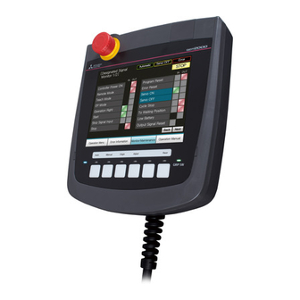
- Page 43 OVERVIEW Handy GOT The Handy GOT (hereinafter abbreviated as GOT) is used as an operation terminal in connection with the controllers such as MELSEC-FX, Q series or third party PLCs. It is an all-in-one operation terminal that is equipped with the display unit with touch switches integrated with the mechanical keys (operation switches) for inputting a command to a machine.
- Page 44 1.1 Features Display unit The TFT color LCD with high intensity, wide viewing angle and high definition is adopted as the display unit. Monitoring for turning ON/OFF bit devices of a PLC, forced turning ON/OFF the bit devices of a PLC, monitoring the word device set value/current value and changing that numeric values are easily made.
-
Page 45: Rough Procedure
1.1.1 Rough procedure The outline procedures before operating GOT and the descriptions of each item are shown below. Refer to GT Designer3 Version1 Screen Design Manual Install GT Designer3 in the PC. (Fundamentals). Refer to GT Designer3 Version1 Screen Design Manual Create project data. - Page 46 1 - 4 1. OVERVIEW 1.1 Features...
-
Page 47: Overall Configuration
Protective sheet CF card Connector conversion box Drawing PC Commercially available Memory card CF card Memory card adaptor The GT16 Handy cannot be connected to a bar code reader or a printer. 2 - 1 2. SYSTEM CONFIGURATION 2.1 Overall Configuration... -
Page 48: System Equipment
G T * * H - * * * * * * 60 : Dedicated for 6.5" H : For Handy GOT 16 : Dedicated for GT16 15 : Dedicated for GT15 11 : Dedicated for GT11 10 : Dedicated for GT10... -
Page 49: Option
The following products are the accessories of the GOT main unit. Sheets for operation switch name characters (one for each of OHP and reference dimensions sheet) Two keys for selector switch GT16 Handy GOT General Description (describes product outline, specifications, external dimensions, etc.) 2.2.2 OPTION... - Page 50 Connection cables for OMRON PLCs (Sold separately) Product Cable Model name Description name length GT09-C30R40101-9P For connecting Connector Conversion Box to OMRON PLC, serial communication module, serial communication board GT09-C100R40101-9P GT09-C30R40103-5T RS-422 cable For connecting Connector Conversion Box to serial communication board GT09-C100R40103-5T GT09-C30R40102-9P For connecting Connector Conversion Box to OMRON rack type host link unit,...
- Page 51 Connection cables for HITACHI PLCs (Sold separately) Product Cable Model name Description name length RS-232 GT09-C30R21301-9S For connecting Connector Conversion Box to HITACHI communication module cable GT09-C30R41301-9S RS-422 For connecting Connector Conversion Box to HITACHI PLC cable GT09-C100R41301-9S Connection cables for HITACHI IES PLCs (Sold separately) Product Cable Model name...
- Page 52 Connection cables for YOKOGAWA PLCs (Sold separately) Product Cable Model name Description name length GT09-C30R40301-6T GT09-C100R40301-6T For connecting Connector Conversion Box to YOKOGAWA PC link module GT09-C30R40302-6T GT09-C100R40302-6T RS-422 cable GT09-C30R40303-6T GT09-C100R40303-6T For connecting Connector Conversion Box to YOKOGAWA temperature controller GT09-C30R40304-6T GT09-C100R40304-6T For connecting Connector Conversion Box to YOKOGAWA CPU port/D-Sub 9-pin...
- Page 53 USB memory (Sold separately) Product name Model name Contents USB memory Commercially-available USB memory Some models with the operations checked by our company are usable. For the operation-checked models, refer to "List of valid devices applicable for GOT1000 series" (GOT-A-0010) separately available, or contact your local distributor.
- Page 54 2 - 8 2. SYSTEM CONFIGURATION 2.2 System Equipment...
-
Page 55: General Specifications
SPECIFICATIONS 3.1 General Specifications Item Specifications Display section 0 to 40 Operating ambient Other than temperature 0 to 40 display section Storage ambient temperature -20 to 60 Operating ambient humidity 10 to 90% RH, non-condensing Storage ambient humidity 10 to 90% RH, non-condensing Half- Frequency Acceleration... -
Page 56: Performance Specifications
3.2 Performance Specifications The performance specifications are as follows. Item Specifications Type TFT color liquid crystal display (High intensity and wide angle view) Screen size 6.5" Resolution 480 dots Display size W132.5(5.22) H99.4(3.91)[mm](inch) 16-dot standard font: 80 characters 30 lines, Display Display character 12-dot standard font: 106 characters... - Page 57 (Excluding projections such as the 201(7.91)(W)×230(9.06)(H)×97(3.82)(D)[mm](inch) emergency stop switch) Weight Approx. 1.2kg (GT16 Handy main unit only) Compatible software package Version1.14Q or later (GT Designer3 version) Bright dots (always lit) and dark dots (unlit) may appear on a liquid crystal display panel due to its characteristics. It is impossible to completely avoid this symptom, as the liquid crystal display comprises of a great number of display elements.
-
Page 58: Power Supply Specifications
3.3 Power Supply Specifications Item Specifications Input power supply voltage DC24V(+10% -15%) Power consumption 11.6W (480mA/24VDC) or less At backlight off 8.2W (340mA/24VDC) or less Inrush current 30A or less (maximum load) 2ms Permissible instantaneous Within 5ms power failure time Noise immunity Noise voltage: 1000Vp-p, Noise width: 1 s (by noise simulator of 30 to 100Hz noise frequency) Dielectric withstand voltage... -
Page 59: Battery Specifications
3.4 Battery specifications Battery specifications The following describes the battery specifications for the GT16 Handy. Item Specifications Type Magnesium manganese dioxide lithium primary battery Initial voltage 3.0V Nominal current 1800mAh Storage life Approx.5 years (Operating ambient temperature of 25 ) Total power stoppage time This section■Battery life... - Page 60 3 - 6 3. SPECIFICATIONS 3.4 Battery specifications...
-
Page 61: Front Panel
PARTS NAME 4.1 Front Panel 4.1.1 Name and specifications (1)(2) Operation switch name sheet (prepared by the user) installation example (6) (7) Name Specifications Display section Displays the utility screen and the user creation screen. Touch panel For touch switch operation on the utility screen and the user creation screen. Operation switch (6 switches) Switch for external direct wiring (independent contact) Operation switch name sheet... -
Page 62: Back Panel
4.2 Back Panel 4.2.1 Name and specifications Environmental protection back cover closed Environmental protection back cover opened (10) (11)(12) (13) Terminating resistor setting switch enlarged view ON side Switch No. Terminating resistor Enable Disable Set to “Disable” before shipping OFF side Name Specifications For external cable connection (for PLC, switch and power supply external wiring) (connector: square 42 pins,... -
Page 63: Opening And Closing Of Environmental Protection Back Cover
4.2.3 Changing the grip angle The grip angle can be changed in GT16 Handy. Loosen the five grip angle changing screws on the back surface. Do not loosen or remove the screws marked with * (two screws). -
Page 64: Top Face (Interface)
4.3 Top Face (Interface) 4.3.1 Names and specifications Interface environmental protection cover closed Interface environmental protection cover opened (11) (10) LED2 LED1 (12) Name Specifications Emergency stop switch guard Threaded hole for mounting the GT16H-60ESCOV type emergency stop switch guard (option) (M3) cover installing hole Interface environmental protection Opened and closed when using the USB port, S.MODE switch and reset switch, as well as when inserting... -
Page 65: Ul, Cul Standards
Directives and put a "CE mark" on their products. • This product is designed for use in industrial applications. • Authorized Representative in the European Community: Mitsubishi Electric Europe B.V. Gothaer Str. 8, 40880 Ratingen, Germany 5 - 1 5. -
Page 66: Requirements To Meet Emc Directive
5.2.1 Requirements to Meet EMC Directive EMC Directives are those which require "any strong electromagnetic force is not output to the external.:Emission (electromagnetic interference)" and "It is not influenced by the electromagnetic wave from the external.: Immunity (electromagnetic sensitivity)". Items EMC directive thru Grounding summarize the precautions to use GOT and configure the mechanical unit in order to match the EMC directives. - Page 67 Control panel Make sure to combine the GT16 Handy GOT with the Connector Conversion Box to comply with the EMC directive. The Connector conversion box is an open type device (device installed to another device) and must be installed in a conductive control panel.
-
Page 68: Emc Directive-Compliant System Configuration
POINT POINT POINT (1) System configuration GT16 Handy conforms to the EMC Directive only when used in the connection type above, via connector conversion box. (2) Connected devices If connecting to the PLC or microcomputer other than Mitsubishi products (MELSEC-Q series, MELSEC-L series, MELSEC-QnA , MELSEC-A series or MELSEC-FX series) please refer to the EMC Directive compliance manual for that specific device. - Page 69 About the cable used Any device which utilizes a data communication function is susceptible to the wider effects of local EMC noise. Therefore, when installing any communication cables care should always be taken with the routing and location of those cables.
-
Page 70: Precautions For Wiring/Connecting The Emc Directive-Compliant Product
5.2.3 Precautions for Wiring/Connecting the EMC Directive-Compliant Product Wire and connect GOT1000 series equipments as instructed below. If the GOT1000 series equipments are configured in a way different from the following instructions, the system may not comply with EMC directives. ... - Page 71 POINT POINT POINT Configure the system to meet the EMC Directive specifications for the connected device when connecting the GOT to a controller. The following gives the instructions to ensure the machinery comply with the EMC Directive. However, the manufacturer of the machinery must finally determine how to make it comply with the EMC Directives: if it is actually compliant with the EMC Directives.
- Page 72 5 - 8 5. UL, cUL STANDARDS AND EMC DIRECTIVE 5.2 EMC Directive...
-
Page 73: Applicable Cf Card
HD G MAC. ADD. 12. 34. 56. 78 .90. 12 MAC. ADD. 12. 34. 56. 78 .90. 12 Rating plate: HD BootOS BootOS MITSUBISHI ELECTRIC CORPORATION MITSUBISHI ELECTRIC CORPORATION Version Version MADE IN JAPAN MADE IN JAPAN 6 - 1 6. -
Page 74: Installing And Removing Procedures Of The Cf Card
6.1.2 Installing and removing procedures of the CF card Install/remove the CF card with the power supply of GOT is OFF or CF card access switch is "OFF". Installing Open the interface environmental protection cover in the arrow-pointing direction. Front Set the CF card access switch of the GOT to "OFF", and make sure that the CF card access... - Page 75 Removing Open the interface environmental protection cover in the arrow-pointing direction. Front Set the CF card access switch of the GOT to "OFF." Make sure that the CF card access LED Interface environmental turns off. protection cover When the CF card access LED turns off, the CF card can be installed or removed even during the GOT power on.
-
Page 76: Memory Card Adaptor
6.2 Memory Card Adaptor The memory card adaptor is used to convert the CF card into the memory card (Type II). Install the memory card adaptor to a PC equipped with a PCMCIA interface, to write the OS or project data on the CF card from the PC or load alarm history data from the CF card to the PC. -
Page 77: Battery
6.4 Battery The battery backs up clock data and data stored in the built-in RAM (D drive) including maintenance report, and system log data. A battery is installed to Handy GOT when Handy GOT is shipped from the factory. 6.4.1 Applicable battery The following battery is applicable for Handy GOT. -
Page 78: Protective Sheet
6.5 Protective Sheet The protective sheet is used to protect the operation surface from damage or dirt when the touch key of GOT display section is operated. For the Handy GOT, the protective sheet is attached for transportation. (It is different from the one described in this chapter.) 6.5.1 Applicable protective sheet Product name... -
Page 79: Emergency Stop Switch Guard Cover
6.6 Emergency Stop Switch Guard Cover The emergency stop SW guard cover is attached to prevent the emergency stop SW from being operated incorrectly. 6.6.1 Applicable emergency stop SW guard cover The following emergency stop SW guard cover is applicable for the Handy GOT. Product name Model Contents... -
Page 80: Connector Conversion Box
6.7 Connector Conversion Box The Connector Conversion Box is used to connect with the external connection devices such as PLC. 6.7.1 Applicable Connector Conversion Box The following Connector Conversion Box is applicable for the GT16 Handy. Product name Model Contents... - Page 81 Connects the external connection device via Ethernet with using a LAN cable. connector (Ethernet: RJ-45 module jack) Rotary switch (U) Sets the ID number of GT16-CNB-42S. Sets one ID number with using both rotary switches (U) and (L). Rotary switch (L) Enables the recognition function of ID number (ON=Valid, OFF=Invalid).
- Page 82 External dimensions (GT16H-CNB-42S) 56 (2.21 " ) 55 (2.17 " ) 110 (4.34 " ) about 65 (2.56 " ) about 130 (5.12 " ) * Space required for connecting the cable Unit: mm (inch) External cable connected 6 - 10 6.
- Page 83 Installation (GT16H-CNB-42S) The Connector Conversion Box can be installed on the panel face directly or on the DIN rail. (1) Mounting on the panel face (When setting the connector for Handy GOT connection and the power supply switch on the panel surface) (a) Direct mounting on the panel face Drill a mounting slot of the Drill 4- 5±0.5 (0.2 "...
- Page 84 (2) Mounting on the panel face (When installing the Connector Conversion Box on the panel surface) (a) Direct mounting on the panel face Drill a mounting slot of the following size on the panel face. (b) Mounting on the panel face Install the Connector Conversion Box on the panel face (mounting surface).
- Page 85 Connector conversion adapter installation Installing the connector conversion adapter and the flange is required to connect the RS-485 unfastened cable with the connector conversion adapter. (1) Installation of the connector conversion adapter GT10-9PT5S (sold separately) and the flange (packed together with the Connector Conversion Box) Install to the adapter and the flange with two screws which are packed together with the connector conversion adapter.
- Page 86 Wiring to the connector and the terminal block (1) Pin assignment and signal names The 42-pin connector of the external cable is converted to the PLC connection connector (D-sub 9pin, module jack) and the following terminal block. Terminal block 1) #4-40UNC (Inch screw thread) External device...
- Page 87 (c) Terminal block 1) , 2) Terminal block 1) (Terminal block for power supply and emergency stop switch) Terminal block 2) (Terminal block for Handy GOT operation switches, grip switch, keylock switch) GT16H-CNB-42S GT16H-CNB-42S Terminal block 1) Application Terminal block 2) Application Terminal No.
- Page 88 (2) Wiring to the terminal block Terminal screws are M3. Wire as described below. Do not tighten the terminal screws within the specified torque. Doing so can cause a failure or malfunction. Terminal Solderless Terminal Solderless screw terminal screw terminal 6.2mm or less 6.2mm...
- Page 89 ID recognition function When connecting with controllers such as PLC via Ethernet, GT16 Handy can acquire ID number which is set by the rotary switch of the Conversion Box of the connection target. ID number can be used as information for switching the station number.
- Page 90 (1) Setting the ID number Set the ID number with the rotary switch of the Connector Conversion Box. Setting range is 0 to 255 (FF Set the second digit of the hexadecimal with "U", and the first digit of the hexadecimal with "L". After setting the ID number, turn the ID number valid/invalid selection switch to valid (ON).
- Page 91 HINT HINT HINT Example of the station No. switching setting procedure using the ID recognition function of the connector conversion box. The following shows an example of the station No. switching setting procedure using the ID recognition function of the connector conversion box. Here, an example to set the station No. switching device value using the status observation function is explained.
- Page 92 Make the MODBUS/RTU communication settings using RS232 to connect the GOT to the connector conversion box. • Ethernet setting Set all PLCs which the GOT may be connected to via Ethernet. Here, an example when [N/W No.] is fixed to 1 is explained. •...
- Page 93 Set the status observation function. • Operation trigger setting Set the GOT internal device GB40 (always ON during the GOT operation) as the conditional trigger of the status observation function. (1) If [Common] [Status Observation...] from the menu is selected, the Status Observation dialog box is displayed.
- Page 94 • Operation setting Store the rotary switch value into the station No. switching device (GD500). The station No. switching device value is an unsigned 16bits data where the upper 8bits are the network No. and the lower 8bits are the PC No. (1) Set [Data Set 16bit] to [Action] and [Unsigned BIN] to [Data] in the Action tab.
- Page 95 (7) Tick the check box of [Fixed] and enter "256". In this example, since N/W No. is fixed to 1, "256" is entered. For fixed values, enter the value of "256 N/W No.". Click the [OK] button when entering is completed. (8) After checking that both Trigger and Action are set, click the [OK] button.
- Page 96 Set the project data to use the station No. switching. When [Screen] [Screen Property...] is selected, the Screen Property dialog box is displayed. Tick the check box of [Switch Station No.] in the [Basic] tab. Perform this operation in all screens where the station No. is switched. Place objects on the screen.
-
Page 97: Connector Conversion Box (Gt16H-Cnb-37S)
6.7.3 Connector Conversion Box (GT16H-CNB-37S) Part name and External dimensions Terminal block cover opened 82 (3.22") 37.5 (1.47") Weight: Approx. 0.2kg Unit: mm (inch) Name Specification Connector for Handy GOT (D-Sub, 37pin, female type) Connects a Handy GOT through an external connection cable. connector model name: 17JE-13370-37(D23A)-FA (DDK) or equivalent Supplies the power to the Handy GOT. - Page 98 Installation (GT16H-CNB-37S) The Connector Conversion Box can be installed on the panel face directly or with mounting bracket offered as an accessory. (1) Direct mounting on the panel face Drill a mounting slot of the following size on the panel face. 18 (0.7") 28 (1.1") 18 (0.7")
- Page 99 Installation with the mounting fixtures (1) Installing the mounting fixtures Install the supplied mounting fixtures to the connector conversion box. Tighten the mounting screws within the specified torque range. Tightening torque 0.49 to 0.68 N•m Mounting bracket (accessory) Mounting screw (accessory) M3×3 (2) Installing on the panel face Install the connector conversion box on the panel face (mounting surface).
- Page 100 Pin layout and signal names of the connector and the terminal block The D-Sub 37pin connector of the external cable is converted to the PLC connection connector (module jack) and the following terminal block. Terminal block 2) Terminal block 1) M2.6(Metric screw thread) External connection device communication connector...
- Page 101 (1) Terminal block 1), 2) Terminal block 2) (Terminal block for emargency stop switch and selector switch) Terminal block 1) (Terminal block for power supply and Handy GOT operation switch) GT16H-CNB-37S GT16H-C -37PE Connector for the Handy GOT connection Application Terminal block D-Sub 37pin Signal name...
- Page 102 6 - 30 6. OPTION 6.7 Connector Conversion Box...
-
Page 103: Installing Procedure
INSTALLATION [MOUNTING PRECAUTIONS] WARNING Be sure to shut off all phases of the external power supply used by the system before mounting or removing the GOT to/from the panel. Always turn off the power ON/OFF switch on the connector conversion box before connecting or disconnecting the GOT to it. -
Page 104: Hanging On A Wall
7.1.2 Hanging on a wall When operating the Handy GOT with hanging on a wall, use the hook for hanging on a wall on the back. Hook for hanging on walls Load (approx. 1.5 to 5 kg) is applied to the wall depending on the weight of the GOT (approx. 1.2kg) main unit and the length of the connection cable. -
Page 105: Installing To/Removing From Panel
7.1.4 Installing to/removing from panel Installing the Connector Conversion Box (GT16H-CNB-42S) on the panel (1) Overview The following describes the panel processing when the GOT is installed or removed by attaching a Connector Conversion Box to the control panel or operation panel. Handy GOT Control panel or operation panel... - Page 106 7 - 4 7. INSTALLATION 7.1 Installing Procedure...
-
Page 107: Overview Of Communication Cable
COMMUNICATION CABLE 8.1 Overview of Communication Cable The following communication cables are available. Wiring of power supply, Controller Connector Conversion Box Handy GOT emergency stop switch, operation switch, etc. Communication with PLC, External cable PLC connection cable temperature controller, inverter, servo amplifier, etc. •... - Page 108 POINT POINT POINT Selection of RS-232 connection and RS-422/485 connection The Handy GOT can be connected to a controller with either of RS-232 or RS-422/485 connection. The selection of RS-232 connection and RS-422/485 connection is made using the cable connector for PLC communication in the environmental protection back cover.
-
Page 109: Installing And Removing Of External Cable
8.1.1 Installing and removing of external cable Installation procedure of external cable Check that the 24VDC power to the external cable is OFF. Insert the connector adjusting the triangle marks of the main unit side connector and cable side connector. After inserting the connector, push the lock lever. - Page 110 8 - 4 8. COMMUNICATION CABLE 8.1 Overview of Communication Cable...
- Page 111 HANDLING OF POWER WIRING AND SWITCH [WIRING PRECAUTIONS] WARNING Make sure to attach the back cover to the Handy GOT before turning on the power and starting operation after the installation or wiring work. Otherwise, electrical shock may be caused. Be sure to shut off all phases of the external power supply used by the system before wiring.
- Page 112 POINT POINT POINT General preventive measures against noise There are two kinds of noises: Radiated noise that is transmitted into the air and Conductive noise that is directly transmitted along connected lines. Countermeasures must be taken considering both kinds of noises and referring to the following 3 points. (1) Protecting against noise (a) Keep signal lines away from noise sources such as a power cable or a highpower drive circuit.
-
Page 113: Internal Wiring Diagram Of Gt16 Handy
9.1 Internal Wiring Diagram of GT16 Handy Each switch is wired inside the GT16 Handy as shown in the following diagram. Display unit DC24V+ Power supply Display LED DC24G Display circuit SW1 LED Display section SW2 LED SW-COM Touch panel... -
Page 114: Power Wiring
9.2 Power Wiring 9.2.1 Power wiring and grounding GOT power is supplied from the external power. In addition, the following table shows the input power supply voltage and the consumed current. Specifications Item GT1665HS-VTBD Input power supply voltage 24VDC(+10% -15%) Power consumption 11.6W or less (480mA/24VDC) At backlight off... -
Page 115: The Cause Of Malfunctions Related Wiring/Remedy
9.2.2 The cause of malfunctions related wiring/Remedy Grounding of the GOT may cause electric potential difference and noise interference, which may result in GOT malfunctions. These problems may be resolved by taking the following measures. Wiring path of the GOT's ground cable and power line Bundling the GOT's ground cable and power line together can cause interference noise, which may result in malfunctions. - Page 116 • Remedy 1 (Refer to the figures Remedy 1-1 and 1-2 below.) If the electric potential difference between the ground cable and the panel that houses the GOT is creating problems, connect the ground cable to the panel also. If the wiring method as shown in Remedy 1-1 is not feasible, follow Remedy 1-2. Connector Connector conversion box...
-
Page 117: Wiring Inside And Outside The Panel
9.3 Wiring inside and outside the panel 9.3.1 Wiring inside Run power lines, servo amplifier drive wires, and communication cables so that they do not cross each other. Noise interference that is generated by cables that cross each other may cause malfunctions. Surge suppressors are an effective way to filter out surge noise that is generated from no fuse breakers (NFB), electromagnetic contactors (MC), relays (RA), solenoid valves, and induction motors. -
Page 118: Attaching Surge Killers To Control Equipment
9.3.3 Attaching surge killers to control equipment If communication errors happen in synch with the on/off signals from certain control equipment (referred to as "load" hereafter) such as no fuse breakers, electromagnetic contactors, relays, solenoid valves, and induction motors, surge noise interference is suspected. -
Page 119: Switch Wiring
9.4 Switch Wiring 9.4.1 Overview for switch Operation switch display LED Grip switch display LED Name Abbreviations Specifications Operation switch (6 switches) SW1 to SW6 Switch for external direct wiring (independent contact) Emergency stop switch ES-1,ES-2,ES-3 Switch for external direct wiring (independent contact) Grip switch DSW-1,DSW-2 Switch for external direct wiring (independent contact) -
Page 120: Switch Wiring Example
ES3B ES3B For setting emergency stop For avoiding emergency stop status when GT16 Handy is status when GT16 Handy is removed removed The internal contact is closed when the power switch of the connector conversion box is turned OFF or the Connector Conversion Box is not supplied with the power (POWER LED turns off.) - Page 121 ES3B ES3B For setting emergency stop For avoiding emergency stop status when GT16 Handy is status when GT16 Handy is removed removed The internal contact is closed when the power switch of the connector conversion box is turned OFF or the Connector Conversion Box is not supplied with the power (POWER LED turns off.)
-
Page 122: Operation Switch Wiring
9.4.3 Operation switch wiring The operation switch is connected to the PLC through an external cable and the Connector Conversion Box. Connection example Connector GT16 Handy conversion box Terminal block 2) SW-COM Pin layout Terminal No. Model name... -
Page 123: Led Setting Of Operation Switch
9.4.5 LED setting of operation switch For operation check, the green LED is attached to the six operation switches (SW1 to SW6). Each LED is related to the bit 0 to bit 5 of the word device. The LED is lit when the bit value is 1, and not lit when it is 0. ... - Page 124 Drawing software settings The read device of the system information is set by the screen editor software as follows. Select [GOT Environmental Setting] of [Common] to open the [System Information...] window. Tick the check box of [Use System Information]. Set the read device.
-
Page 125: Operation Switch Name Sheet Creation
9.4.6 Operation switch name sheet creation This section describes the operation switch name sheet creation. Creating the name sheet Prepare the name sheet board and OHP sheet (transparent and colorless sheet) included in this product. Write a original switch name for the user on the name sheet board. Create the name sheet in the following dimensions. -
Page 126: Emergency Stop Switch Wiring
When turning ON/OFF the external device power, set the load up to 24VDC/1A (contact specification). • For the emergency stop circuit, be sure to configurate the circuit outside the PLC. Connector Connector GT16 Handy GT16 Handy conversion box conversion box... - Page 127 (2) When avoiding to set the Connector Conversion Box to the emergency stop state while Handy GOT is removed Connector conversion box GT16 Handy Terminal block 1) Used as control signals of external ES-1 ES1A device power ON/OFF ES1B Internal contact...
-
Page 128: Grip Switch
9.4.9 Grip switch wiring The grip switch is a switch with two circuits of the above 3-position system a contact. Connection example Connector GT16 Handy conversion box Terminal block 2) Used as input signals of PLC DSW-1 Used as control... -
Page 129: Led Settings Of Grip Switch
The keylock switch (2-position SW) is used with wiring to the input of PLC Connection example The following describes the connection example when the notch of the switch is set to the left. Connector conversion box Terminal GT16 Handy Notch of block 2) the switch is set to the left KSW-C KSW-1 KSW-2 Set the load up to 24VDC/1A (contact specification) for each contact. - Page 130 9 - 20 9. HANDLING OF POWER WIRING AND SWITCH 9.4 Switch Wiring...
-
Page 131: Utility Execution
10. UTILITY FUNCTION Utility is a function, which carries out connection of GOT and controller, screen display and operation method settings, program/data control and self-check etc. Refer to the following for the utility function list. 10.2 Utility Function List 10.1 Utility Execution For utility execution, utility has to be displayed by installing BootOS and standard monitor OS in the C drive (built in flash memory). -
Page 132: Utility Function List
Displaying the screen for cleaning the display 11.1.3 Video/RGB setting GOT main unit setup Multimedia setting These functions are not available for GT16 Handy. License management Setting the GOT operation when a device with the same IP address as Behavior of duplicate IPs 11.1.4 that of the GOT is added to the network afterwards. - Page 133 Item Functions overview Reference MELSEC-L troubleshooting Monitor screens 1 Log viewer 13.1 Motion SFC monitor Monitor screens 2 Motion program (SV43) editor Setting the data storage location for the MELSEC-Q/L/QnA ladder monitor Q/L/QnA ladder monitor 13.2.1 function Setting the storage locations for backup data and backup settings, and 13.2.2 Debug setting setting the maximum number of backup data...
-
Page 134: Utility Function
Operator information passwords, setting the automatic logout time, password expiration date 15.2.7 and external authentication ID Fingerprint information These functions are not available for GT16 Handy. OS information Installing or uploading OS, displaying OS property, checking OS data 15.3.1 OS/project... -
Page 135: Utility Display
10.3 Utility Display To display setting screens for each utility, the main menu has to be displayed first. (1) Main menu The menu items that can be set at the GOT utility are displayed. Touching a menu item in the main menu will display the setting screen or following selection screen for the item. (2) System message switch button This button switches the language used for the utility or system alarms. - Page 136 POINT POINT POINT When starting the GOT without selecting any language or the selected language and the installed fonts are not matched The following screen will be displayed. Touching the button of a desired language restarts the GOT and the language is switched to the selected one. HINT HINT HINT...
-
Page 137: Display Operation Of Main Menu
10.3.1 Display operation of main menu The following four types of operation can display the main menu. (Display the main menu after installing the basic OS from GT Designer3 to the GOT built in flash memory.) (1) When project data is undownloaded If the power supply of GOT turns ON, the main menu is displayed automatically after title display. -
Page 138: Main Menu
(3) When touching special function switch (utility) If you touch the special function switch (utility) while user-created screen is displayed, the main menu is displayed. The special function switch (utility) can be set as a touch switch that is displayed on a user-created screen by GT Designer3. -
Page 139: Utility Basic Configuration
10.3.2 Utility basic configuration The basic configuration of utility is as follows. Title display Close/Return button Scroll button Screen (1) Title display The screen title name is displayed in title display part. As the screen is composed of multiple layers, the title including these layers is displayed. Title display Title display (2) Close/Return button... -
Page 140: Basic Operation Of Settings Change
10.3.3 Basic operation of settings change Change of setting value Close/Return button Setting item Select button (1) Setting item, select button Touch the select button to change the settings. The setting methods differ depending on the setting items. The following types of setting method are available. (a) Switch the setting value. - Page 141 Keyboard operation Touch the numerical value to be changed. Keyboard for numerical input is displayed and cursor is displayed simultaneously. The key board display position changes by the position of numerical value touched. (At the time of numerical input, displayed in the position which will not interrupt the inputting.) Cursor Keyboard Input numeric with keyboard.
- Page 142 10 - 12 10. UTILITY FUNCTION 10.3 Utility Display...
-
Page 143: Got Main Unit Function Settings
Cleaning the display section 11-6 Video/RGB Setting These functions are not available for GT16 Handy. Multimedia setting Setting the GOT operation when a device with the same IP address as that of the GOT is added to the network Behavior of duplicate IPs 11-8 afterwards. -
Page 144: Operation Of Time Setting
Display operation of time setting Main menu Time setting 10.3 Utility Display) Touch Time setting Set the [Time setting] and Clock setting Operation of time setting (1) Time setting Setup the method to adjust the time between GOT data and the clock data of controller connected to the GOT. Setting Description Adjust the time of GOT clock data to the clock data of controller. - Page 145 If touch the setup item, the setup contents is changed. Adjust Broadcast Adjust/Broadcast None If touch the [OK] button, the GOT restarts and operates with the changed settings. If touch the [Cancel] button, the changed settings are canceled and the screen returns to the Main Menu.
- Page 146 (2) Clock display Carry out the display and setting of GOT clock data. The setup methods of clock data are shown below. If touch the clock display section, the keyboard for input is displayed and the clock update stops. Input time with the keyboard by referring to the table below.
-
Page 147: Transparent Setting (Transparent Mode Setting)
11.1.2 Transparent setting (Transparent mode setting) Function of the transparent mode When using the multi-channel function, the channel No. of a controller to which the FA transparent function is executed can be specified. For the multi-channel function and FA transparent function, refer to the following. 30. -
Page 148: Cleaning Of Display Section (Clean)
11.1.3 Cleaning of display section (Clean) In utility, the screen can be set as not to be effected by touching the screen when clean with clothes. Refer to the below for the cleaning procedure. 18.3 Cleaning Method Display operation of Clean Main menu GOT main unit setup GOT setup... - Page 149 Operation of Clean After cleaning the screen, touch the screen following the instruction displayed. After touching the screen, the screen returns to the Main Menu. The following screen is displayed. 11 - 7 11. DISPLAY AND OPERATION SETTINGS (GOT SET UP) 11.1 GOT Main Unit Function Settings...
-
Page 150: Behavior Of Duplicate Ips
11.1.4 Behavior of duplicate IPs Setting function for Behavior of duplicate IPs The GOT operation can be set when a device with the same IP address as that of the GOT is added to the network afterwards. Items Description Setting range Maintain a network connection(rec) The GOT operation can be set when a device with the same IP address as... - Page 151 Display operation of Behavior of duplicate IPs Main menu GOT setup GOT main unit setup 10.3 Utility Display) Touch Touch [GOT setup] [GOT main unit setup] Touch [Behavior of duplicate IPs] Behavior of duplicate IPs Setting operation for Behavior of duplicate IPs If touch the setup item, the setup contents is changed.
- Page 152 POINT POINT POINT (1) Precautions for selecting [Do not maintain a network connection] When selecting [Do not maintain a network connection], the GOT is disconnected from the network at the addition of a device with the same IP address as the GOT. Therefore, there is a possibility that the running GOT cannot be communicated by IP address setting mistakes or intended actions by malicious users, and the system control may be influenced by those errors.
-
Page 153: License Management
11.1.5 License Management For using functions which require a license, register the license for the GOT. For releasing a registered license for the GOT, also execute on the license management screen. Items Description Setting range ® ® server function Registers/deletes the license of the VNC server function. - Page 154 Setting operation of license management (1) When registering a license number for the GOT Touch the license number input area on the license management screen, and then the keyboard appears on the bottom of the screen. Touch the [Regist] button to register the input license number.
-
Page 155: Display Settings
Brightness, Contrast 11.2.4Brightness, contrast adjustment Sensor detect level Sensor detect time These functions are not available for GT16 Handy. Sensor off delay Only selectable languages are displayed. The selectable languages differ depending on the fonts installed in the GOT. For details of the fonts, refer to the following manual. -
Page 156: Display Operation Of Display Setting
11.2.2 Display operation of display setting Main menu GOT setup (10.3 Utility Display) Touch Touch [GOT setup] [Display] Display Touch an item to change settings 11 - 14 11. DISPLAY AND OPERATION SETTINGS (GOT SET UP) 11.2 Display Settings... -
Page 157: Display Setting Operations
11.2.3 Display setting operations Language If the setting item is touched, the Language screen is displayed. If touch the language to be displayed, the language is selected and the screen returns to the [Display] screen. If touch the [OK] button, the GOT restarts and operates with the changed settings. - Page 158 Opening screen, screen save time If touching the setting (numerical), keyboard is displayed. Input numeric with the keyboard. If touch the [OK] button, the GOT restarts and operates with the changed settings. If touch the [Cancel] button, the changed settings are canceled and the screen returns to the Main Menu.
-
Page 159: Brightness, Contrast Adjustment
11.2.4 Brightness, contrast adjustment Functions of the brightness, contrast The brightness can be adjusted. Function Description Brightness setting Brightness of display part can be adjusted by 8 levels. Display operation of brightness, contrast Main Menu GOT main unit setup Display 10.3 Utility Display) Touch... -
Page 160: Operation Settings (Settings Regarding Operation)
11.3 Operation Settings (Settings Regarding Operation) 11.3.1 Operation setting functions Setting regarding GOT operation can be set. The items which can be set are described below. If touch the each item part, the respective setting becomes possible. Function Description Setting range OFF/SHORT/LONG Buzzer volume setting Buzzer volume setting can be changed. -
Page 161: Display Operation Of Operation Setting
POINT POINT POINT Operation settings by GT Designer3 Select [Common Settings] [GOT Environment Settings] [GOT Setup] from GT Designer3 to make the settings of buzzer sound and buzzer sound at window move. When change a part of the setting, change the setting by the GOT display setting after downloading the project data. -
Page 162: Setting Operation Of Operation
11.3.3 Setting operation of operation Buzzer volume, window move buzzer, Touch detection mode Setting items are changed if setting item is touched. If touch the [OK] button, the GOT restarts and operates with the changed settings. If touch the [Cancel] button, the changed settings are canceled and the screen returns to the Main Menu. -
Page 163: Security Level Change
server function setting Refer to the following for the VNC server function setting operation. 11.3.9 VNC(R) server function setting operation 11.3.4 Security level change Security level change functions Changes the security level to the same security level set by each object or screen switch. To change the security level, input the password of the security level which is set in GT Designer3. - Page 164 Security level change operation (1) Password input operation By touching [0] to [9], [A] to [F] key, the password of the changed security level is input. When correcting the input character, touch [Del] key to delete the correcting character and input the password again.
-
Page 165: Utility Call Key Setting
11.3.5 Utility call key setting Utility call key setting function The key position for calling the main menu of the utility can be specified. For the key position, 0 or 1 point can be specified from 4 corners on the screen. By keeping pressing the screen, a setting to switch the screen to the utility is available. -
Page 166: Utility Call Key Setting Operation
Utility call key setting operation ● Touch displayed at the 4 corners of the setting screen. ● The button repeats with every touch. ● Set the corner to be set to a key position to For the key position, 0 or 1 point only can be set. When setting 1 point, specify the time to switch to the utility in case of keeping pressing the key position. -
Page 167: Adjusting The Touch Panel Position (Touch Panel Calibration Setting)
11.3.6 Adjusting the touch panel position (Touch panel calibration setting) Touch panel calibration setting function Touch panel reading error can be corrected. Normally the adjustment is not required, however, the difference between a touched position and the object position may occur as the period of use elapses. - Page 168 Touch panel calibration operation Touch the point displayed on the screen with the finger one by one to make the setting. Touch the center of the displayed on the upper left precisely. Touch the point displayed on the upper right. Touch the point displayed on the lower left.
-
Page 169: Usb Mouse/Keyboard Setting
11.3.7 USB mouse/keyboard setting USB mouse/keyboard function To install and use the USB mouse/keyboard on the GOT, set the USB mouse/keyboard. USB mouse/keyboard setting display operation Main menu GOT setup Operation 10.3 Utility Display) Touch [GOT setup] Touch [Operation] Touch [USB mouse/keyboard]... - Page 170 To move the mouse cursor to the touched position, touch the setting item of [Interlock with mouse cursor touch operation]. The setting content is changed by touching. (YES To use the USB keyboard, touch the setting item of [USB keyboard type]. The setting content is changed by touching.
-
Page 171: Softgot-Got Link Function Setting
11.3.8 SoftGOT-GOT Link Function Setting SoftGOT-GOT link function The authorization of the SoftGOT-GOT link function can be set, and the exclusive authorization can be obtained or released. Only the GOT can obtain the exclusive authorization. While the GOT has the exclusive authorization, GT SoftGOT1000 cannot obtain the authorization. - Page 172 SoftGOT-GOT link function setting operation (1) Exclusive authorization obtained state (a) Obtaining the exclusive authorization Touch the [Obtain] button to display the dialog box. Touch the [OK] button to obtain the exclusive authorization. Touch the [Cancel] button to stop obtaining the exclusive authorization.
- Page 173 (3) Operating priority guaranteed time Touch the operating priority guaranteed time display area to display a keyboard. Enter the operating priority guaranteed time with the keyboard. If touch the [OK] button, the changed settings are reflected and the screen returns to the [Operation] screen.
-
Page 174: Vnc(R) Server Function Setting Operation
11.3.9 VNC(R) server function setting operation server function setting In the VNC server function setting, the authorization guarantee time for the VNC server function can be set. For the details of the VNC server function, refer to the following. GT Designer3 Version1 Screen Design Manual (Functions) Function Description... - Page 175 server function setting operation (1) Operating priority guaranteed time Touch the input field for [Operating priority guaranteed time] to display a keyboard. Input the authorization guarantee time with the keyboard. Touch the [OK] button to confirm the new setting and the screen returns to the [Operation] screen.
-
Page 176: Maintenance Function
11.4 Maintenance Function 11.4.1 Maintenance time setting Energization time, touch count and writing times used as a standard for the maintenance time are set. For using the maintenance time notification, a battery is required. Refer to the following for the details of battery. 6.OPTION ... - Page 177 Display operation of maintenance timing setting Main menu GOT setup GOT maintenance 10.3 Utility Display) Touch Touch [GOT setup] [Maintenance Touch timing setting] [GOT maintenance] Maintenance time notification For the addition times as power on addition time, refer to the following. 11.4.2 Addition times reset ...
-
Page 178: Addition Times Reset
11.4.2 Addition times reset Displays the present value of Backlight maintenance time notification period, Display section maintenance time notification period, Touch key maintenance time notification count and Built-in flash memory maintenance time notification count which are additioned for the maintenance time notification, respectively and resets these values. For maintenance time notification setting, refer to the following. - Page 179 Operation of Addition times reset If touch [Reset] button of each item, the addition time or the addition count becomes "0". If touch the [OK] button, the changed settings are reflected and the screen returns to the [GOT maintenance] screen. If touch the [Cancel] button, the changed settings are canceled and the screen returns to the [GOT maintenance] screen.
-
Page 180: Got Start Time
11.4.3 GOT start time GOT start time function GOT start time is the function to display the following date and time. • Start time of GOT • Current time of GOT • Operating hours of GOT Display operation of GOT start time Main menu GOT setup GOT maintenance... - Page 181 Display of GOT start time Item Description Displays the time when the GOT was powered on or reset-restarted (OS installation, Start Time communication setting change). Current Time Displays the current time. Displays operating hours of the GOT. The displayed operating hours is the accumulated time while GOT is powered on or reset- Operating hours restarted (OS installation, communication setting change).
-
Page 182: Got Information
11.4.4 GOT information GOT information function GOT information is the function to display the following information. • Communication driver installed in the GOT • MAC address • Capacity of the CF card mounted on A drive Display operation of GOT information Main menu GOT setup GOT maintenance... - Page 183 Display of GOT information Item Description Communication driver Displays the communication driver written to the GOT. MAC address Displays the MAC address. CFCard Displays the capacity of the CF card mounted on A drive. 11 - 41 11. DISPLAY AND OPERATION SETTINGS (GOT SET UP) 11.4 Maintenance Function...
- Page 184 11 - 42 11. DISPLAY AND OPERATION SETTINGS (GOT SET UP) 11.4 Maintenance Function...
-
Page 185: Communication Setting
12. COMMUNICATION INTERFACE SETTING (COMMUNICATION SETTING) In the communication setting, the communication interface names and the related communication channel, communication driver names display and channel numbers are set. Moreover, in the communication detail setting, the communication interface details are set. (Communication parameters setting) Function Description... -
Page 186: Communication Setting Contents
(When change a communication driver, the alternative communication driver has to be installed in GOT in advance.) (2) Standard interface display BOX Display the communication interface included as standard in GT16 Handy. There are the following 4 types. For GT16 Handy, extend I/F-1 and I/F-2 are not available. - Page 187 (3) Channel number specification menu BOX Set channel No. to use with standard interface. Refer to This section (4) for driver that can be assigned to each channel. : Set when the communication interface is not used. 1 to 4 : Set when connecting to a controller. : Set when connecting with PC (GT Designer3 ).
-
Page 188: Communication Setting Operation
12.1.4 Communication setting operation Channel-Driver assign operation The following describes how to operate the Channel-Driver assign. The example of changing to the direct CPU connection (Communication driver: [A/QnA/L/QCPU, LJ71C24, QJ71C24]) for the GOT of the computer link connection (Communication driver: [AJ71QC24, MELDAS C6*]) is used. POINT POINT POINT... - Page 189 As the communication driver ([A/QnA/L/QCPU, L/ QJ71C24]) installed in the GOT is displayed, touch it. The screen returns to the [Channel-Driver assign] screen. If touch the [OK] button, the changed settings are reflected and the screen returns to the [Communication Setting] screen. If touch the [Cancel] button, the changed settings are canceled and the screen returns to the [Communication Setting] screen.
- Page 190 12.2 Communication Detail Setting) 5V power supply setting operation GT16 Handy cannot provide 5VDC power to the controllers from the RS-232 interface regardless of the setting of the 5V power provision. 12 - 6 12. COMMUNICATION INTERFACE SETTING (COMMUNICATION SETTING)
- Page 191 Assign Ethernet I/F operation The following describes how to operate the Ethernet I/F assign. The setting operation is same as that of the communication setting screen. Touch the [Assign Ethernet I/F] button in [Communication Setting]. After the screen shown left is displayed, touch the channel number specification menu BOX when changing the channel number.
-
Page 192: Communication Detail Setting
12.2 Communication Detail Setting 12.2.1 Communication detail setting functions Function Description Communication Set various communication parameters of communication devices. parameters setting The settable parameters differ according to the communication device. Keyword setting For the FX series PLCs, key word for protecting program in the PLC can be set. Key word deleting For the FX series PLCs, key word for protecting program in the PLC can be deleted. - Page 193 Assign Ethernet I/F Several drivers are assigned to the same Ethernet interface. However, only one GOT IP address is assigned per interface. By changing the settings of one interface, the GOT IP address, GOT port No. download, default gateway and subnet mask settings of other drivers, which are assigned to the same interface, are also changed.
-
Page 194: Display Contents Of Communication Detail Setting
12.2.3 Display contents of communication detail setting The contents of communication detail setting varies according to driver type. This section explains setting items different from the communication detail setting of the GT Designer3. For setting items other than described in this section, refer to the following. 17. - Page 195 Key word registration, deletion and protection delete MELSEC-FX (1) Registration Register key words. Touching the [Regist] key displays the selection screen for the registration. For a FX PLC that is not compatible with the customer keyword, the keyboard for the keyword input of displayed.
- Page 196 When the registration is selected or the [Regist] key is touched on a PLC not compatible with the customer keyword, the keyboard for the keyword input is displayed in a pop-up window. When the keyword is input and the [Enter] key is touched, registration is completed. When [Keyword and Customer Keyword] is selected on the selection screen for the registration, the Customer Keyword entry screen of is displayed.
- Page 197 POINT POINT POINT (1) Selection of keyword protection level For the devices which can perform the online operation of FX PLC, 3 levels of protection can be set. When the monitoring or setting change by online devices is needed, set the keyword taking the following into consideration.
- Page 198 (2) Delete Registered keyword is deleted. Touching the [Delete] key pops up a keyboard for keyword input. When the correct keyword is input and the [Enter] key is touched, the keyword is deleted. Target PLC Settings FX PLC compatible with 2nd keyword Input a keyword to be deleted.
-
Page 199: Ethernet Setting
12.3 Ethernet Setting 12.3.1 Ethernet setting functions The contents of the Ethernet set in GT Designer3 can be checked. The setting of the host station can be changed. For ethernet setting, refer to the following. GOT1000 Series Connection Manual for GT Works3 12.3.2 Ethernet setting display operation Communication setting Main menu... -
Page 200: Display Contents Of Ethernet Setting
12.3.3 Display contents of Ethernet setting The following describes the setting items and the display contents of the Ethernet setting. (1) Channel selection tab Channels can be switched. Switching to the channel which does not have the Ethernet setting is not available. [*] is displayed on the tab of the channel whose setting is changed. - Page 201 Change of host Touch the device to be set as the host. If touch the [OK] button, the GOT restarts and operates with the changed settings. If touch the [Cancel] button, the changed settings are canceled and the screen returns to the [Communication Setting] screen.
- Page 202 12 - 18 12. COMMUNICATION INTERFACE SETTING (COMMUNICATION SETTING) 12.3 Ethernet Setting...
-
Page 203: Monitor Screens
Motion monitor The servo monitoring and parameter settings of the motion controller CPU (Q series) are available. CNC monitor This function is not available for GT16 Handy. A list editor The sequence program of ACPU can be list edited. FX list editor The sequence program of FXCPU can be list edited. -
Page 204: Display Operation Of Monitor Screens
13.1.2 Display operation of monitor screens Main menu Debug Monitor screens 10.3 Utility Display) Touch Touch Touch [Monitor [Debug] the debug to be screens] operated. Debug is displayed. (For System monitor) 13 - 2 13. DEBUG 13.1 Monitor Screens... -
Page 205: Debug Setting
13.2 Debug Setting 13.2.1 Q/L/QnA ladder monitor setting Storage locations and others for data to be used for the ladder monitor function can be set. Saving the ladder data cuts out the need for reading the ladder data from PLC CPU at the next GOT start-up, enabling to start the ladder monitoring earlier. - Page 206 Display operation of Q/L/QnA ladder monitor Debug setting Main menu Debug 10.3 Utility Display) Touch [Debug] Touch Touch [Q/L/QnA ladder monitor] [Debug setting] [Q/L/QnA ladder monitor] Select the ladder data storage location of the Q/L/QnA ladder monitor. Q/L/QnA ladder monitor setting operation Setting items are changed if setting item is touched.
-
Page 207: Backup/Restoration Setting
13.2.2 Backup/restoration setting The storage location for backup data can be set. For how to use the backup/restoration, refer to the following manual. GOT1000 Series Extended/Option Functions Manual for GT Works3 Set the following items with touching the items on the GOT. Function Description Setting range... - Page 208 Backup/restoration setting operation (1) Drive for backup setting, drive for backup data Touch a setting item, and then the setting is changed. If touch the [OK] button, the changed settings are reflected and the screen returns to the [Debug Setting] screen.
-
Page 209: Trigger Backup Settings
13.2.3 Trigger backup settings When the conditions of the trigger specified for each backup setting (Rise, Time) are met, the GOT automatically backs up data. How to use the trigger backup, refer to the following manual. GOT1000 Series Extended/Option Functions Manual for GT Works3 ... -
Page 210: Trigger Backup Setting Operation
Trigger backup setting operation Touch a setting item for the trigger type, and then the setting is changed. (None Rise Time) None The GOT does not execute the trigger backup. Rise The GOT backs up data when the trigger device turns on. -
Page 211: Memory/Data Control
GOT data package acquisition 13-11 or USB memory are possible. CNC data I/O function This function is not available for GT16 Handy. Memory card format Formatting CF card or USB memory is possible. 13-14 Displaying the flash memory empty area size available for the user of each drive and Memory information Boot drive empty area size is possible. -
Page 212: Backup/Restoration
13.3.2 Backup/restoration Display operation of backup/restoration Memory/data control Main menu Debug 10.3 Utility Display) Touch Touch [Debug] Touch [Backup/restoration] [Memory/data control] Backup/restoration Touch an item to change settings Operation of backup/restoration Backup/restore data from the controller to GOT, or erase backup data with the backup/restoration. GOT data package acquisition is also possible. -
Page 213: Got Data Package Acquisition
13.3.3 GOT data package acquisition GOT data package acquisition function The GOT data package acquisition copies the installed OS or data in the GOT main unit to the CF card or USB memory. • OS (Boot OS, standard monitor OS, communication driver, extended function OS, option OS) •... -
Page 214: Display Example Of Got Data Package Acquisition
Display example of GOT data package acquisition Item Description Displays the drive where OS and data can be copied. Select Drive When the memory card is not installed, [A: Built-in CF card] is not displayed. [E: USB drive] is displayed even if the USB memory is not installed. Copy Touching the button starts copying. - Page 215 The display depends on the status of copy (Example: Dialog box after touching the [Copy] button) destination and setup. Operate with following the displayed dialog box. After copying OS and data, the dialog box for notifying the completion appears. Touching the [OK] button closes the dialog box. POINT POINT POINT...
-
Page 216: Memory Card Format
13.3.4 Memory card format Function of the memory card format Format the CF card or USB memory. Display operation of memory card format Memory/data control Main menu Debug 10.3 Utility Display) Touch [Debug] Touch Touch [Memory/data control] [Memory card format] Memory card format 13 - 14 13. - Page 217 Operating the memory card format Install the CF card or USB memory to GOT. Refer to the following for inserting/removing method of CF card or USB memory. 6.1.2Installing and removing procedures of the CF card 6.3.2Installing and removing procedures of the USB memory Touch and select the drive to format by drive selection.
-
Page 218: Memory Information
13.3.5 Memory information Memory information functions Displays the flash memory empty area size available for the user of each drive and Boot drive empty area size. Confirming memory empty space is enabled without connecting a personal computer. Memory information display operation Memory/data control Main menu Debug... -
Page 219: Usb Device Status Display
13.3.6 USB device status display Function of USB device status display This function displays a list of the USB device connection status in the GOT. Also, this screen is used to remove the USB device from GOT. Display operation of USB device status display Main menu Debug Memory/data control... - Page 220 USB device status display operation When the USB device is installed to GOT, the screen shown left is displayed. USB mass storage is displayed in Device, and [Stop] button is displayed in Attach. When the [Stop] button is touched, the dialog box shown left is displayed.
-
Page 221: Sram Control
13.3.7 SRAM control Function of SRAM control The SRAM user area usage can be confirmed, data in the SRAM user area can be backed up or restored, and the SRAM user area is initialized. For the available functions in the SRAM user area, refer to the following. GT Designer3 Version1 Screen Design Manual (Functions) ... - Page 222 Display example of SRAM control (11) (10) (14) (12) (13) Item Description Check box Touch the check box to select or clear the item. Displays the used functions in the order of the advanced system alarm, advanced user alarm, and logging Function name function.
- Page 223 SRAM control operation (1) Operation to initialize all or selected areas of the SRAM user area Perform any of the following operations. • To initialize all areas of the SRAM user area, touch the [Initialize all] button. • To initialize selected areas of the SRAM user area, select the check box of the area to be initialized, and then touch the [Initialize selected area] button.
- Page 224 (2) Operation to restore data To restore data in the SRAM user area to a drive Select the drive where the data is stored, and then touch the [Restoration] button. The dialog box shown left appears. Check the description of the dialog box. To restore all data in the SRAM user area, touch the [OK] button.
-
Page 225: Motion Program (Sv43) I/O
(3) Operation to back up all data in the SRAM user area To back up data in the SRAM user area to a drive Select the drive where the data is stored, and then touch the [Backup all area] button. The dialog box shown left appears. - Page 226 13 - 24 13. DEBUG 13.3 Memory/Data Control...
-
Page 227: Diagnostic Functions
I/O check Carries out RS-232, RS-422/485 connecting target confirmation and self-loopback check. 14-15 Network status display This function is not available for GT16 Handy. Ethernet status check Sends a ping to check the Ethernet connection status. 14-18 14 - 1 14. -
Page 228: System Alarm
14.1.1 System alarm System alarm function System alarm is the function to display error code and error message when an error occurs in GOT, controller or network. System alarms can be reset on the System alarm display screen. For details of system alarm, refer to the following manual. GT Designer3 Version1 Screen Design Manual (Fundamentals) ... - Page 229 Operation of system alarm display (1) System alarm display resetting Eliminate each cause of the system alarm being occurred. Error causes can be identified by the error code, error message and channel No. displayed on the System alarm screen. 19.
-
Page 230: Memory Check
14.1.2 Memory check Memory check function Memory check function carries out the write/read check of A drive (Standard CF Card), C drive (Built-in flash memory) and E drive (USB drive). Function Description A drive memory check Checks whether the memory (CF card) of the A drive can be read/written normally. C drive memory check Checks whether the memory (Built-in flash memory) of the C drive can be read/written normally. - Page 231 Memory check operation Carries out write/read check of memory. POINT POINT POINT When drive is not displayed When the drive (memory) to check is not displayed, confirm the mounting procedure or memory type with reference to the following. 6.1 CF Card 6.3 USB Memory When no faults are found in mounting, etc, a memory failure may be arisen.
- Page 232 POINT POINT POINT (1) Password change The password cannot be changed. When input password error, the cancel dialog box is displayed. If touch [OK], returns to the Memory check screen. (2) When error is found in memory When error is found by memory check, the dialog box indicating the area in which the error occurred is displayed.
-
Page 233: Drawing Check
14.1.3 Drawing check Drawing check function The drawing check function carries out display checks as missing bit check, color check, basic figure display check, move check among screens. Display operation of drawing check Main menu Self check Diagnostic functions 10.3 Utility Display) Touch Touch... -
Page 234: Drawing Check Operation
Drawing check operation The screen for drawing check can be displayed by touching [Drawing check] on the Display check menu. (1) Before execute drawing check Touching the upper right part of the screen proceeds to the next check in each step during drawing check. Touching the upper left part of the screen returns to the [Display check] screen. - Page 235 (c) Move check among screens • Pattern 1: Shape transformation, color check The drawn figures are displayed in order and at regular intervals. If the shape and color are displayed visually in order, it is normal. To Pattern 2 Pattern 1 •...
- Page 236 • Pattern 3: Shape transformation, color check The overlapped shapes of pattern 1 and pattern 2 are displayed. If the shape and color are displayed visually in order, it is normal. To Pattern 4 • Pattern 4: Shape Check The drawn figures are displayed in order and at regular intervals. If the shape and color are displayed visually in order, it is normal.
-
Page 237: Font Check
14.1.4 Font check Font check function The font check is a function which confirms fonts installed in GOT. The character data of the font is displayed on the upper left part of the screen one by one. Display operation of Font check Main menu Diagnostic functions Self check... - Page 238 Font check operation Font check starts by touching [Font Check] in the [Display check] screen. The character data of the built-in font (in the built-in flash memory) can be checked visually to confirm the font drawings by displaying the character data serially on the screen. (1) Before execute font check Touching the upper right part of the screen proceeds to the next check in each step during Font check.
-
Page 239: Touch Panel Check
14.1.5 Touch panel check Touch panel check function Touch panel check function checks whether there are no dead zone area in 16 dots 16 dots. Display operation of Touch panel check Main menu Self check Diagnostic functions 10.3 Utility Display) Touch [Self check] Touch... - Page 240 Touch panel check operations If touch [Touch panel check] of self-check, a black-filled screen is displayed over the entire screen area. Touch a part of the screen. The touched part becomes a yellow-filled display. Black-filled screen Yellow color If touch the upper left part, returns to the self-check. Upper-left touch position POINT POINT...
-
Page 241: I/O Check
14.1.6 I/O check I/O check function The I/O check is a function which checks whether GOT and PLC can communicate with each other. If I/O check ends normally, the communication interface and the connection cable hardwares are normal. To execute I/O check, the communication driver has to be installed in GOT in advance from GT Designer3. Note that the GOT restarts when this function is performed. - Page 242 [I/O check]. (2) Self-loopback If touch [Self], the hardware check of RS-232 interface is carried out. For preparation for the self-loopback communication GT16 Handy check, insert the connector for self-loopback check (Rear face) Connector conversion box...
- Page 243 After selecting [Self], the transferred data and received data are verified through the self-loopback connector. When the GOT cannot receive the data during the data transmission, the dialog box shown left appears and the GOT restarts in five seconds. When the dialog box shown left appears, check the following.
-
Page 244: Ethernet Status Check
14.1.7 Ethernet status check Ethernet status check function Ethernet status check is a function that sends a ping to check the connection status with the equipment on the Ethernet. Display operation of Ethernet status check Main menu Self check Diagnostic functions 10.3 Utility Display) Touch... -
Page 245: Batch Self Check
14.2 Batch Self Check 14.2.1 Batch self check The Batch self check collects data about energization time, installed OS and others, and can display it in View self check results menu. In the Batch self check screen, the CF card or USB memory can be set as save destination of the log. Also, the following information are displayed in View self check results menu. -
Page 246: Operation Of Batch Self Check
14.2.3 Operation of batch self check Batch self check The display switches A drive E drive Do not export A drive as touching [Export the system status log]. When selecting A drive, install the CF card. When selecting the E drive, install the USB memory. If Batch self check is started without installing the CF card or USB memory, the system status log will not be saved. - Page 247 (1) Display example of details screen Touch the items to display the following screens. Touch the button to return to the View self check results menu. Touch the button in the left bottom of the screen to display the previous screen. Touch the button in the right bottom of the screen to display the next screen.
- Page 248 14 - 22 14. SELF CHECK 14.2 Batch Self Check...
-
Page 249: Data Storage Location
15. DATA CONTROL OS, project data (screen data) or alarm data which is written in the GOT, CF card or USB memory can be displayed, and data can be transferred between GOT and CF card or USB memory. The format of the CF card or USB memory is also possible. 15.1 Data Storage Location 15.1.1 Data type and the storage location ... - Page 250 At maintenance ■ GOT main unit Resource data Read C drive (Built-in flash memory) Alarm Recipe Copy Copy Logging Alarm Alarm Operation Log GT Designer3 Hard copy Hard copy Hard copy Copy files on Windows E drive A drive (USB drive) (Standard CF card) Alarm...
-
Page 251: Os Version Confirmation
HD G MAC. ADD. 12. 34. 56. 78 .90. 12 MAC. ADD. 12. 34. 56. 78 .90. 12 Rating plate: HD BootOS BootOS MITSUBISHI ELECTRIC CORPORATION MITSUBISHI ELECTRIC CORPORATION Version Version MADE IN JAPAN MADE IN JAPAN 15 - 3 15. -
Page 252: Capacity Confirmation Of The Project Data Downloading Location
15.1.3 Capacity confirmation of the project data downloading location When download the project data, confirm the capacity of the user area in the drive to which transferred, the transferred project data size, the transfer size and buffering area size of the optional function OS in advance to judge whether to carry out the download. -
Page 253: Various Data Control
15.2 Various Data Control 15.2.1 Alarm information Function of alarm information The extended alarm log file or alarm log file held by each drive (A: Built-in CF card, C: Flash Memory, E: USB drive) is displayed. The functions below can be carried out for files. The USB drive only stores log files, and cannot be displayed. -
Page 254: The Display Example Of Alarm Information
The display example of alarm information (3) (4) (10) (11) Number Item Description The drive which displays file or folder can be selected. When CF card or USB memory is not installed, the following drives are not displayed. Select drive •... - Page 255 Alarm information operation (1) The display operation of alarm information If touch a drive of [select drive], the information of the touched drive is displayed. If touch a folder name, the information of the touched folder is displayed. If touch a folder of ". .", the information of the folder of the one upper hierarchy is displayed.
- Page 256 (2) G1A CSV conversion operation, G1A TXT conversion operation The selected G1A file is converted to CSV file or TXT file. Touch and select the G1A file to convert into a CSV file or a TXT file. The following dialog box is displayed when touching the following button according to the file type to convert to.
- Page 257 (3) Deletion operation Deletes selected files. Touch and select the file to delete. If touch [Del] button, the dialog box mentioned left is displayed. If touch [OK] button, the file is deleted. If touch [Cancel] button, the deletion is canceled. When the deletion is completed, the completion dialog box is displayed.
- Page 258 (4) Copy operation Copies the selected file. Touch and select the file to copy. If touch [Copy] button, the message [Please select a destination.] is displayed in the left bottom of the screen. If the copy destination folder is touched, the screen display is changed to the folder of copy destination.
- Page 259 (5) Graph operation Displays the selected extended alarm log file in a graph. When the extended alarm watch (advanced user alarm, advanced system alarm) is set in history mode, the selected extended alarm log file is displayed in historical graph ( (a)Historical graph display).
- Page 260 (a) Historical graph display • Displays the generated time ( ), confirmed time ( ) and restored ( ) time of each alarm. • Displays the time scales by 30 minutes interval in the bottom of the graph. • The alarms generated in the order of registering alarm are displayed. •...
-
Page 261: Advanced Recipe Information
15.2.2 Advanced recipe information POINT POINT POINT Before using advanced recipe information For writing/reading into/from a controller with this function or editing of advanced recipe file on the personal computer, refer to the following manual. Specifications and operating procedure are described. GT Designer3 Version1 Screen Design Manual (Functions) ... - Page 262 Operation of advanced recipe information display Main menu Data control Data control 10.3 Utility Display) Touch Touch Touch [Data control] [Data control] [Advanced Recipe information] Advanced Recipe information Operate advanced recipe file. 15 - 14 15. DATA CONTROL 15.2 Various Data Control...
-
Page 263: Example Of Advanced Recipe Information Display
Example of advanced recipe information display (1) Advanced recipe information screen (3) (4) (10) (11) Number Item Description Drive The target drive can be selected. (Even if CF card is not installed, this message appears.) Check box If the check box is selected, up to 512 files can be selected. Indicates whether the displayed name is file or folder. - Page 264 (2) Advanced recipe record list screen (1) Touching the [Execute] button on the advanced recipe information screen after selecting the advanced recipe file, this screen appears. Records selected in each advanced recipe file can be displayed or saved/loaded. Number Item Description Record No.
- Page 265 Advanced recipe information operation (1) Display operation of advanced recipe information If touch a drive of select drive, the information of the touched drive is displayed. If touch a folder name, the information of the touched folder is displayed. If touch a folder of ".
- Page 266 (2) G1P CSV conversion operation, G1P TXT conversion operation Advanced recipe file (G1P file) is converted to CSV file or Unicode text file that can be displayed/edited on personal computer. Touch and select the G1P file to convert into a CSV file or a Unicode text file.
- Page 267 (3) CSV/TXT G1P conversion operation CSV file or Unicode text file is converted to an advanced recipe file (G1P file). To select the file, touch the check box of CSV file or Unicode text file to be converted to a G1P file. Touch the [CSV/TXT->G1P] button to display [Please select destination] at the lower left corner of the screen.
- Page 268 (4) Delete operation Folder and file to be used on advanced recipe are deleted. Touch and select the file/folder to delete. If touch [Del] button, the dialog box mentioned left is displayed. If touch [OK] button, the file/folder is deleted. (While executing, "Processing..."...
- Page 269 (5) Copy operation Folder to be used in advanced recipe is copied. Touch and select the file to copy. Touch the [Copy] button. Select the target folder. (Selecting a folder is not needed for outputting directly below the drive.) At this time, it cannot be copied into the same folder where the file exists.
- Page 270 (6) Move operation Files to be used in advanced recipe are moved. Touch and select the file to move. Touch the [Move] button. Select the target folder. (Selecting a folder is not needed for moving directly below the drive.) If touch [Exec.] button, the dialog box shown left is displayed.
- Page 271 (7) Rename operation File name to be used in advanced recipe is changed. Touch and select the file to change the name. If touch the [Rename] button, displays the screen shown left, then input the file name to be renamed. By touching the following button, input text type is changed.
- Page 272 (8) Folder create operation Folder to be used in advanced recipe is created. Touch the [Create Folder] button. The input key window shown left appears, then input the file name to be created. By touching the following button, input text type is changed.
- Page 273 (9) G1P file create operation Advanced recipe file (G1P file) is created. When advanced recipe is only executed on Utility, advanced recipe file should be created with this function in advance. Touch the [Create G1P] button. The screen to select the advanced recipe setting is displayed.
- Page 274 If touch the [Enter] button, the dialog box shown left is displayed. Touch the [OK] button. When the file, whose name is the same, exists in the destination folder, the dialog box shown left appears without starting the creation. Touching the [OK] button overwrites the file. If touch the [Cancel] button, cancels creating.
- Page 275 (10) Record load operation Selected record value is loaded in the device of controller. Select the recipe file and touch the [Execute] button. As the Advanced Recipe Record List screen is displayed, select the record comment to which you want to load the device value. If touch the button, the dialog box Load record...
- Page 276 (11) Record save operation Device value of a controller is saved in the selected record. Select the recipe file and touch the [Execute] button. As the Advanced Recipe Record List screen is displayed, select the record comment for saving the device value. If touch the button, the screen shown Save record...
- Page 277 (12) Record match operation Verifies weather selected record matches to the device value of the controller. After executing loading/saving with advanced recipe, verifies weather its contents are reflected. Select the recipe file and touch the [Execute] button. As the Advanced Recipe Record List screen is displayed, select the record comment for matching the device value.
- Page 278 (13) Device value delete operation The device value of selected record is deleted (without value) and changed to record only for reading. (The record name is not deleted.) Select the recipe file and touch the [Execute] button. As the Advanced Recipe Record List screen is displayed, select the record comment to be deleted.
- Page 279 Precautions (1) When creating folder/file (a) Number of characters set for folder or file name when creating folder/file. GOT recognizes file location according to path explained below. Specify folder or file name, and total characters of path cannot exceed 78 characters. Users only can rename folder or file name.
- Page 280 Precautions for operation (a) Precautions during folder/file operation (Create/Delete/Copy/File output, etc) Even if CF card access switch has been turned OFF while GOT is processing folders and files, the processing continues to be executed. (Example: Even if CF card access switch has been turned OFF while GOT is creating a folder, the folder is created.) Therefore, do not pull out the CF card while the "Processing..."...
-
Page 281: Logging Information
15.2.3 Logging information Function of logging information Logging files created with the logging function can be copied, deleted or renamed, etc. Without using a personal computer, you can manage logging files on the GOT. For details of the logging function, refer to the following manual. GT Designer3 Version1 Screen Design Manual (Functions) Function Description... -
Page 282: Example Of Logging Information Display
Example of logging information display (3) (4) (10) (11) Number Item Description Drive The target drive can be selected. (Even if CF card is not installed, this message appears.) Check box If the check box is selected, up to 512 files can be selected. Indicates whether the displayed name is file or folder. - Page 283 Logging information operation (1) Display operation of logging information If touch a drive of select drive, the information of the touched drive is displayed. If touch a folder name, the information of the touched folder is displayed. If touch a folder of ". .", the information of the folder of the one upper hierarchy is displayed.
- Page 284 (2) Operation of G1L CSV conversion G1L TXT conversion Logging file (G1L file) is converted to CSV file or Unicode text file that can be displayed/edited on personal computer. Touch and select the G1L file to convert into a CSV file or a Unicode text file. Touch the following button in accordance with destination file type.
- Page 285 (3) Delete operation Folder and file to be used on logging are deleted. Touch and select the file/folder to delete. If touch [Del] button, the dialog box mentioned left is displayed. If touch [OK] button, the file/folder is deleted. (While executing, "Processing..." message appears on the screen.) If touch [Cancel] button, the deletion is canceled.
- Page 286 (4) Copy operation Folder to be used in logging is copied. Touch and select the file to copy. Touch the [Copy] button. Select the target folder. (Selecting a folder is not needed for outputting directly below the drive.) At this time, it cannot be copied into the same folder where the file exists.
- Page 287 (5) Move operation An operation log file is moved. Touch and select the file to move. Touch the [Move] button. Select the target folder. (Selecting a folder is not needed for moving directly below the drive.) If touch the [Exec.] button, the dialog box shown left is displayed.
- Page 288 (6) Rename operation An operation log file is changed. Touch and select the file to change the name. If touch the [Rename] button, displays thescreen shown left, then input the file name to be renamed. By touching the following button, input text type is changed.
- Page 289 (7) Folder create operation An operation log folder is created. Touch the [Create Folder] button. The input key window shown left appears, then input the file name to be created. By touching the following button, input text type is changed. : English capital : Numeric/Symbol If touch the [Enter] button, displays the dialog box...
- Page 290 Precautions (1) Precautions for create/delete (a) When creating folder/file Number of characters set for folder or file name. GOT recognizes file location according to path explained below. Specify folder or file name, and total characters of path cannot exceed 78 characters. Users only can rename folder or file name.
-
Page 291: Operation Log Information
15.2.4 Operation log information Function of operation log information Operation log files created with the operation log function can be copied, deleted or renamed, etc. Without using a personal computer, you can manage operation log files on the GOT. For details of the operation log function, refer to the following manual. - Page 292 HINT HINT HINT Default display drive when displaying the operation log information screen. When [Save to] of the [Environmental Setting] dialog box is set in GT Designer3, the default display drive for displaying the operation log information screen is the drive set in GT Designer3. GT Designer3 Version1 Screen Design Manual (Functions) (22.
-
Page 293: Example Of Operation Log Information Display
Example of operation log information display (3) (4) (10) (11) Number Item Description Drive The target drive can be selected. (Even if CF card is not installed, this message appears.) Check box If the check box is selected, up to 512 files can be selected. Indicates whether the displayed name is file or folder. - Page 294 Operation log information operation (1) Display operation of operation log information If touch a drive of select drive, the information of the touched drive is displayed. If touch a folder name, the information of the touched folder is displayed. If touch a folder of ".
- Page 295 (2) Operation of G1O CSV conversion G1O TXT conversion Operation log file (G1O file) is converted to CSV file or Unicode text file that can be displayed/edited on personal computer. Touch and select the G1O file to convert into a CSV file or a Unicode text file.
- Page 296 (3) Delete operation Folder and file to be used on operation log are deleted. Touch and select the file/folder to delete. If touch [Del] button, the dialog box mentioned left is displayed. If touch [OK] button, the file/folder is deleted. (While executing, "Processing..."...
- Page 297 (4) Copy operation An operation log file is copied. Touch and select the file to copy. Touch the [Copy] button. Select the target folder. (Selecting a folder is not needed for outputting directly below the drive.) At this time, it cannot be copied into the same folder where the file exists.
- Page 298 (5) Move operation An operation log file is moved. Touch and select the file to move. Touch the [Move] button. Select the target folder. (Selecting a folder is not needed for moving directly below the drive.) If touch the [Exec.] button, the dialog box shown left is displayed.
- Page 299 (6) Rename operation An operation log file is changed. Touch and select the file to change the name. If touch the [Rename] button, displays thescreen shown left, then input the file name to be renamed. By touching the following button, input text type is changed.
- Page 300 (7) Folder create operation An operation log folder is created. Touch the [Create Folder] button. The input key window shown left appears, then input the file name to be created. By touching the following button, input text type is changed. : English capital : Numeric/Symbol If touch the [Enter] button, displays the dialog box...
- Page 301 (8) List display Displays operation logs in an operation log file in a list. Touch and select the file to display the list. Touching the button displays the list. In the list, the following contents can be checked. Display items: Date Time Screen No.
- Page 302 (a) Display order switching operation Touch [Date (ascending)] / [Date (descending)] in the list to switch the display order of operation logs. [Date (ascending)] and [Date (descending)] are switched every time the button is touched. The buttons show the current display order. •...
- Page 303 Touching the [Enter] button displays the dialog box on the left. Touch the [OK] button. (When processing is being executed, the "Processing" message is displayed on the screen.) The results found are displayed and the dialog box on the left is displayed. To continue a search, touch the [OK] button.
- Page 304 (9) Latest display The latest operation log files are selected and displayed in a list. If touch the [Latest] button, the latest one in the operation log files is displayed in a list. In the list, the following contents can be checked. Display items: Date Time Screen No.
- Page 305 Precautions (1) Precautions for create/delete (a) Number of characters set for folder or file name when creating folder/file. GOT recognizes file location according to path explained below. Specify folder or file name, and total characters of path cannot exceed 78 characters. Users only can rename folder or file name.
-
Page 306: Hard Copy Information
15.2.5 Hard copy information The function of hardcopy information Carries out delete, copy and move to the file created by the hardcopy function. Refer to the following manual for details of hard copy function. GT Designer3 Version1 Screen Design Manual (Functions) Function Description Reference... - Page 307 Hardcopy information display example (3) (4) (10) (11) Number Item Description The drive which displays file or folder can be selected. When CF card or USB memory is not installed, the following drives are not displayed. Select drive • CF card: [A: Built-in CF card] •...
- Page 308 The operation of hardcopy information (1) Display operation of hardcopy information If touch a drive of select drive, the information of the touched drive is displayed. If touch a folder name, the information in the touched folder is displayed. If touch a name of the folder of ".
- Page 309 (2) Delete operation Deletes the selected file. Touch and select the file to delete. If touch [Del] button, the screen mentioned left is displayed. If touch [OK] button, deletes the file. If touch [Cancel] button, cancel the deletion. When the deletion is completed, the completion dialog box is displayed.
- Page 310 (3) Copy operation Copies the selected file. Touch and select the file to copy. If touch [Copy] button, the dialog [Please select a destination.] is displayed in the left bottom of the screen. If touch the folder of the copy destination, the screen display is changed to the folder of copy destination.
- Page 311 (4) Rename operation Rename the selected file. Touch and select the file to change the name. Touch the [Rename] button, and then the screen shown left is displayed. Input the file name to be changed. Character types to be input can be changed with touching the following buttons.
-
Page 312: Special Data Information
15.2.6 Special data information Special data information function Special data used in the intelligent unit monitor function or others can be copied, deleted, downloaded, or uploaded. For details of special data, refer to the following manual. GT Designer3 Version1 Screen Design Manual (Fundamentals) Function Description Reference... -
Page 313: Special Data Information Display Example
Special data information display example (4) (5) Number Item Description The drive by which a file or folder is displayed can be selected. When CF card or USB memory is not installed, the following drives are not displayed. Select drive •... - Page 314 Special data information operation (1) Special data information display operation If touch a drive in [Select drive], the special data in the drive is displayed. Refer to the following for operation of delete, property, data check and download. Delete......... This section(2) Property........
- Page 315 (3) Property display operation Displays the property of selected special data. Touch the [Property] button after selecting a special data to display Property as shown left. In Property display, the following information is displayed. Item Description Date Displays date and time of file creation. Author Displays the author of the project data.
- Page 316 (5) Download operation Transfers the special data written in the A drive (Standard CF Card) or E drive (USB drive) to the C drive (Built- in flash memory). The GOT monitors C drive data. (This item explains using the A drive.) POINT POINT POINT...
- Page 317 If there is a project data of the same name in the C drive, the screen shown left is displayed. If touch the [OK] button, the project data is downloaded and the project data in the C drive is overwritten. Downloading is canceled when the [Cancel] button is touched When the downloading is completed, the dialog box mentioned left is displayed.
-
Page 318: Operator Information
15.2.7 Operator information Operator management (1) Operator management function The function enables displaying a list of the operator information and adding, changing, or deleting the operator information to be used. A password for operator authentication can be changed when the password is out of date. Functions for the operator authentication (automatic logout time, authentication method, password expiration date, etc.) can be set. - Page 319 (3) Display example of operator management (a) Operator information management screen Item Description Operator Name Displays operator names. Displays operator IDs. Level Displays security levels for operators. Update Displays the last updated dates of the operator information. Operation keys Execution keys for each function Displays and sets the storage location for imported and exported operator information.
- Page 320 Switches the setting of the item disabled and enabled. Make a permanent password : Disabled : Enabled) Use ext. auth. ID The external authentication function cannot be used for GT16 Handy. Ext.auth. ID 15 - 72 15. DATA CONTROL 15.2 Various Data Control...
- Page 321 (4) Operator management operation Touch [Operator management] in the operator setting menu. The Admin password authentication screen is displayed, and then input the administrator password. Character types to be input can be changed with touching the following buttons. : Alphabet capital : Alphabet small letter : Numeric When the input is completed, touch the [Enter] key.
- Page 322 (d) Password (e) Make a permanent password (f) Use ext. auth. ID (g) Ext.auth. ID The external authentication cannot be used for GT16 Handy. Touch the OperatorName, and then the Operator name input dialog box is displayed. Input an operator name.
- Page 323 For changing passwords during editing, touch the password. The New password input dialog box is displayed, and then input a password. When the input is completed, touch the [Enter] key. When the password input is completed, the New password input confirmation dialog box is displayed.
- Page 324 (b) Edit operation Edit the operator information stored in the GOT. Select the operator information to be edited with touching the operator information. Touch the [Edit] button. The Operator information edit screen is displayed, and then touch an item to be edited. (a) Level (b) Password (c) Make a permanent password...
- Page 325 (c) Delete operation Delete the operator information stored in the GOT. Select the operator information to be deleted with touching the operator information. Touch the [Delete] button, and then the dialog box shown left is displayed. Touch the [OK] button, and then the selected operator information is deleted.
- Page 326 (d) Undo operation Restore the current operator information to the previous saved one. Touch the [Undo] button. The dialog box shown left is displayed, and then touch the [OK] button. The Admin password authentication screen is displayed, and then input the administrator password.
- Page 327 (e) Import operation Import the operator information that is already exported to a CF card to the GOT. Touch the [Import] button. The dialog box shown left is displayed. Touch button, and then the Admin password authentication screen is displayed. Input the administrator password.
- Page 328 Export operation Export the operator information stored in the GOT to a CF card. Touch the [Export] button. The dialog box on the left is displayed. Touch the following buttons according to the output format for the file. Binary file: button Binary CSV file:...
- Page 329 Password change (1) Password change function The passwords to be used for the operator authentication can be changed. For the password change, log into the GOT in advance with the operator name corresponding to the password to be changed. (2) Display operation of password change Main menu Data control...
- Page 330 (3) Password change operation Log into the GOT with the operator name corresponding to the password to be changed on the Main Menu screen for the utility. Touch [Password change] in the operator setting menu, and then the Password change dialog box is displayed.
-
Page 331: Function Setting
When the password is out of date after setting the password, the GOT requests the password change. Initial position input The external authentication function cannot be used for GT16 Handy. Valid byte count input (2) Display operation of function setting... - Page 332 (b) Auth method (c) Password expiration date (d) Initial position input (e) Valid byte count input The external authentication cannot be used for GT16 Handy. (a) Touch [Automatic logout time], and then the Automatic logout time edit dialog box is displayed.
- Page 333 (c) Touch [Password expiration date], and then the Password expiration date edit dialog box is displayed. Input the expiration date. When the input is completed, touch the [Enter] key. Touch the [OK] button after all items are input, and then the dialog box shown left is displayed and the input setting is saved.
-
Page 334: Os/Project Information
15.3 OS/Project Information 15.3.1 OS information Function of OS information Each file name/folder name of BootOS and OS (Standard monitor OS, communication driver and optional function OS) by which each drive (A: Standard CF card, C: Built-in flash memory, E: USB memory) holds can be displayed in lists. -
Page 335: Display Example Of Os Information
Display example of OS information Number Item Description The target drive which displays file or folder can be selected. Select drive When the CF card is not installed, [A: Built-in CF Card] is not displayed. If the USB memory is not installed, [E: USB drive] is not displayed. Indicates whether the displayed name is for file or folder. -
Page 336: Operation Of Os Information
Operation of OS information (1) Display operation of OS information If touch a drive in [Select drive], the information of the first folder of the touched drive is displayed. If touch a folder name, the information of the touched folder is displayed. - Page 337 (2) Installation operation BootOS and OS which are written in the A drive (Standard CF card) or E drive (USB drive) can be installed in GOT. (This item explains using the A drive.) Install the CF card to which the BootOS or OS to install is written to the GOT.
- Page 338 (3) Upload operation BootOS and OS in the C drive (Built-in flash memory) can be uploaded to the A drive (Standard CF card) and E drive (USB drive). The CF card after uploading can be used for installing the OS on another GOT. 16.
- Page 339 (4) Property display operation Displays the property of the file stored in the selected folder If touch [Property] button after selecting the property displaying target folder, the Property display shown left is displayed. In Property display, the following information is displayed for each file selected by Item Description...
-
Page 340: Project Information
15.3.2 Project information Functions of the project information The project data files stored in each drive (A: standard CF card, C: built-in flash memory, E: USB drive) can be displayed by lists. In addition, the files can be downloaded, uploaded, deleted or copied, etc. Function Description Reference... -
Page 341: Display Example Of Project Information
Display example of project information Number Item Description The drive by which a file or folder is displayed can be selected. Select drive When the CF card is not connected, [A: Built-in CF card] and [B: Memory card] are not displayed. If the USB memory is not installed, [E: USB drive] is not displayed. - Page 342 Operation of project information (1) Display operation of project information Touch the drive in Select drive. The project data in that drive will be displayed. Touch the project data. It is then selected and highlighted. Refer to the following for operation of delete, copy, property, data check, download, upload.
- Page 343 (3) Copy operation Uploads the project data written in the C drive (Built-in flash memory) to the A drive (Standard CF card) / E drive (USB drive). • Copying to another directory in the same drive • Copying between A drive and E drive Copy to/from C drive is disabled.
- Page 344 Touch [OK] button. If there is no file of the same name in the copy destination folder, starts to copy. When there is a file of the same name in the copy destination folder, the dialog box mentioned left is displayed without starting the copy.
- Page 345 (5) Data check operation Carrys out data check of the selected project file. Touch the [Data check] button after selecting the file Dialog at data check normal for data check. The data check is executed and the result is displayed by the dialog box shown left. If touch [OK] button, the dialog box is closed.
- Page 346 Install the CF card or USB memory in GOT. Refer to the following for inserting/removing method of CF card. 6.1.2 Installing and removing procedures of the CF card 6.3.2 Installing and removing procedures of the USB memory Touch [A: Standard CF Card] in Select drive. If touch the [Download] button, the dialog box mentioned left is displayed.
- Page 347 (b) Setup operation Sets the project data stored in the A drive (Standard CF Card) or E drive (USB drive) to be used in the GOT. The GOT monitors using the monitor data in the A drive. (This item explains using the A drive.) POINT POINT POINT...
- Page 348 (7) Upload/setup cancel operation (a) Upload operation By upload operation, the project data is transferred from the C drive (Built in flash memory) to the A drive (Standard CF card) or E drive (USB drive). The CF card or USB memory after uploading can be used for downloading project data to another GOT. (This item explains using the A drive.) POINT POINT...
- Page 349 (b) Setup cancel operation By setup cancel, setup is canceled. (This item explains using the A drive.) Touch [A: Standard CF Card] in Select drive. If touch the [Upload] button, the screen mentioned left is displayed. If touch the [OK] button, setup cancel is executed. When the setup cancel is completed, the dialog box mentioned left is displayed.
- Page 350 15 - 102 15. DATA CONTROL 15.3 OS/Project Information...
- Page 351 16. INSTALLATION OF COREOS, BOOTOS AND STANDARD MONITOR For executing the GOT utility, install the BootOS and standard monitor OS on the C drive (built-in flash memory) of the GOT, or set the OS boot drive to [A: Standard CF Card] and insert the CF card with OS files into the GOT. (BootOS is installed in the GOT at factory shipment.
-
Page 352: Bootos And Standard Monitor Os Required For Installation
16.1 BootOS and Standard Monitor OS Required for Installation Under-mentioned BootOS and Standard monitor OS are necessary to execute utility. Function overview Storage location name Built-in flash memory C: \G1BOOT\ Required for the control of GOT and the communication between PC and GOT. Installed at factory shipment. -
Page 353: Prior Preparations For Installing Bootos And Standard Monitor Os
16.2 Prior Preparations for Installing BootOS and Standard Monitor OS For the installation using GOT, the CF card or USB memory storing BootOS or standard monitor OS is required. For the method of writing BootOS and standard monitor OS in the CF card or USB memory, the following three methods are available. -
Page 354: Bootos And Standard Monitor Os Installation Using Cf Card Or Usb Memory
16.3 BootOS and Standard Monitor OS Installation Using CF Card or USB Memory There are the following two types for the BootOS, standard monitor OS installation using the CF card or USB memory. (1) Installing when starting the GOT 16.3.1 Installing when starting the GOT) All the OS and project data stored in the CF card or USB memory are transferred to the GOT when powering on the GOT. -
Page 355: Installing When Starting The Got
16.3.1 Installing when starting the GOT The displayed message is different depending on the installation condition of standard monitor OS. When the screen requesting operation is displayed, operate the GOT according to the instructions on the screen. Operation procedure (1) When installing with CF card Power OFF the GOT, switch the CF card access switch to OFF, and install the CF card where the BootOS, standard monitor OS or project data is stored in the CF card interface of the GOT. - Page 356 The GOT restarts automatically after the installation is completed. (When the standard monitor OS is already installed, the GOT restarts by touching the button.) Reboot. After confirming normal restart, confirm that the USB memory access LED is not lit, and remove the USB memory from the USB interface of the GOT.
-
Page 357: Installing Using The Data Control Function (Utility)
16.3.2 Installing using the data control function (Utility) For details of data control function, refer to the following. 15. DATA CONTROL POINT POINT POINT Precautions on executing data control function When execute data control function, standard monitor OS has to be installed in GOT in advance. Thus, this function cannot be used for the initial installation of BootOS, standard monitor OS after purchasing GOT. - Page 358 (2) When installing with USB memory Install the USB memory in which BootOS, standard monitor OS or project data is stored in the CF card interface of GOT. Display the data control function screen (Utility) on the GOT, and install BootOS, standard monitor OS from the USB drive to GOT.
-
Page 359: When Installing The Different Version Of Bootos, Standard Monitor Os
16.4 When Installing the Different Version of BootOS, Standard Monitor OS (1) BootOS installation When installing BootOS, GOT compares the version of the BootOS to be installed with the version of BootOS which is already installed. If the major version of BootOS to be installed is old, execute the following operations to prevent it from being rewritten. - Page 360 HD G MAC. ADD. 12. 34. 56. 78 .90. 12 MAC. ADD. 12. 34. 56. 78 .90. 12 Rating plate: HD BootOS BootOS MITSUBISHI ELECTRIC CORPORATION MITSUBISHI ELECTRIC CORPORATION Version Version MADE IN JAPAN MADE IN JAPAN 16 - 10 16.
-
Page 361: Coreos
16.5 CoreOS Install CoreOS only when the GOT will not be the status of factory shipment even when BootOS is installed. Normally, the CoreOS has not to be installed. POINT POINT POINT Precautions for installing CoreOS When executing the CoreOS installation once, it cannot be canceled on the way. Do not attempt the followings to cancel the installation on the way. - Page 362 Installing the CoreOS Write the CoreOS from GT Designer3 to the CF card. For details of GT Designer3 operation, refer to the following manual. GT Designer3 Version1 Screen Design Manual (Fundamentals) After confirming that the GOT is powered off, install the CF card in the GOT. After installing, switch the CF card access switch on.
- Page 363 Turning the CF card access switch off executes Core OS installation. When the installation is completed, the dialog as shown below is displayed. (The POWER LED of the GOT blinks (green/orange) at the installation completion.) Confirm that the message is displayed and power the GOT off. Remove the CF card after powering the GOT off.
-
Page 364: When The Coreos Cannot Be Installed
16.5.2 When the CoreOS cannot be installed When the CoreOS cannot be installed, confirm the following item. If the CoreOS cannot be installed even after checking the following item, the error may be caused by a hardware failure. Please consult your local Mitsubishi (Electric System) Service center or representative. Error Action (1) Check whether the CF card access switch of the GOT is on. -
Page 365: Setting The Communication Interface
17. DRAWING SOFTWARE SETTINGS (CONTROLLER SETTING AND COMMON SETTINGS) 17.1 Setting the Communication Interface Set the communication interface of GOT and the connected equipment. When using the GOT at the first time, make sure to set the channel of communication interface and the communication driver before writing to GOT. -
Page 366: Setting Connected Equipment (Channel Setting)
17.1.1 Setting connected equipment (Channel setting) Set the channel of the equipment connected to the GOT. Setting Select [Common] [Controller Setting] from the menu. The Controller Setting dialog box appears. Select the channel No. to be used from the list menu. Refer to the following explanations for the setting. - Page 367 Setting item This section describes the setting items of the Manufacturer, Controller Type, Driver and I/F. When using the channel No.2 to No.4, put a check mark at [Use CH*]. Item Description Use CH* Select this item when setting the channel No.2 to No.4. Manufacturer Select the manufacturer of the equipment to be connected to the GOT.
- Page 368 (2) Setting [Controller Type] The types for the selection differs depending on the PLC to be used. For the settings, refer to the following. Type Model name Type Model name Q03UDVCPU R04CPU Q04UDVCPU R08CPU Q06UDVCPU R16CPU Q13UDVCPU R32CPU Q26UDVCPU R120CPU Q12DCCPU-V R16MTCPU Q24DHCCPU-V/VG...
- Page 369 Type Model name Type Model name L02CPU A0J2HCPU-DC24 L06CPU A2CCPU L26CPU L26CPU-BT A2CCPUP21 L02CPU-P A2CCPUR21 MELSEC-L L06CPU-P A2CCPUC24 L26CPU-P MELSEC-A A2CCPUC24-PRF L26CPU-PBT L02SCPU A2CJCPU-S3 L02SCPU-P A1FXCPU NZ2GF-ETB A273UCPU A2UCPU A2UCPU-S1 A273UHCPU A3UCPU A273UHCPU-S3 A4UCPU A373UCPU A2ACPU A373UCPU-S3 A2ACPUP21 A2ACPUR21 A171SCPU A2ACPU-S1 A171SCPU-S3 A2ACPUP21-S1...
- Page 370 Type Model name Type Model name DMC10 FREQROL-S500 DMC50 FREQROL-S500E SDC15 FREQROL-E500 SDC25 SDC26 FREQROL-F500 SDC35 FREQROL-F500L SDC36 FREQROL-F500J SDC20 FREQROL-A500 SDC21 FREQROL 500/700 Series FREQROL-A500L SDC30 SDC31 FREQROL-V500 SDC40A FREQROL-V500L AZBIL SDC/DMC Series SDC40B FREQROL-E700 SDC40G FREQROL-F700 SDC45 FREQROL-F700P SDC46 FREQROL-F700PJ CMF015...
- Page 371 Type Model name Type Model name CS1H JW-21CU CS1G JW-31CUH CS1D JW-50CUH CJ1H JW-22CU OMRON SYSMAC CS/CJ CJ1G JW-32CUH SHARP JW CJ1M JW-33CUH CJ2H JW-70CUH CJ2M JW-100CUH E5AN JW-100CU E5EN Z-512J OMRON THERMAC/INPANEL NEO E5CN ACS-13A / , , C5 E5GN JCS-33A- / , C5...
- Page 372 Type Model name Type Model name FP0-C16CT PXG4 FP0-C32CT PXG5 FP0R FUJI PXR/PXG/PXH FP1-C24C PXG9 FP1-C40C PXH9 SPH200 FP2SH PANASONIC INDUSTRIAL DEVICES SUNX SPH300 MEWNET-FP Series FUJI MICREX-SX-SPH SPH3000 FP10(S) SPH2000 FP10SH FP-M(C20TC) PROGIC-8 FP-M(C32TC) GL120 FP-Σ GL130 FP-X YASKAWA GL/PROGIC8 GL60S H-302 H-702...
- Page 373 Type Model name Type Model name NFCP100 UT35A NFJT100 UT52A F3SP05 UT55A YOKOGAWA GREEN/UT100/UT2000 /UTAdvanced Series F3SP08 UP35A F3SP10 UP55A F3SP20 UM33A F3SP30 H-PCP-J F3FP36 H-PCP-A F3SP21 H-PCP-B F3SP22-0S Z-TIO YOKOGAWA STARDOM/FA-M3 Series F3SP25 Z-DIO F3SP35 Z-CT F3SP28 CB100 F3SP38 CB400 F3SP53 CB500...
- Page 374 Type Model name Type Model name 1761-L10BWA IC697CPU731 1761-L10BWB IC697CPX772 1761-L16AWA IC697CPX782 1761-L16BWA IC697CPX928 1761-L16BWB IC697CPX935 1761-L16BBB IC697CPU780 1761-L32AWA IC697CGR772 1761-L32BWA IC697CGR935 AB MicroLogix1000/1200/1500 Series 1761-L32BWB IC697CPU788 1761-L32BBB IC697CPU789 1761-L32AAA IC697CPM790 1761-L20AWA-5A IC200UAA003 1761-L20BWA-5A IC200UAL004 1761-L20BWB-5A IC200UAL005 1762-L24BWA IC200UAL006 1764-LSP IC200UAA007 1756-L GE Series 90...
- Page 375 Type Model name (Manufacturer) NFCP100 YOKOGAWA NFJT100 TSX P57 203M TSX P57 253M TSX P57 303M TSX P57 353M TSX P57 453M 140 CPU 311 10 MODBUS 140 CPU 434 12U 140 CPU 534 14U Schneider Electric 140 CPU 651 50 140 CPU 651 60 140 CPU 671 60 140 CPU 113 02...
-
Page 376: I/F Communication Setting
17.1.2 I/F communication setting This function displays the list of the GOT communication interfaces. Set the channel and the communication driver to the interface to be used. Setting Select [Common] [I/F Communication Setting] from the menu. The I/F Communication Setting dialog box appears. Make the settings with reference to the following explanation. POINT POINT POINT... - Page 377 Setting item The following describes the setting items of the standard I/F setting.(GT16 Handy does not use the extend I/F setting, RS232 setting.) Item Description Set channel No. and drivers to the GOT standard interfaces. Standard I/F Setting Standard I/F-1, Standard I/F-2, Standard I/F-3, Standard I/F-4 Set the CH No.
-
Page 378: Precautions
POINT POINT POINT Channel No., drivers (1) Channel No.2 to No.4 Use the channel No.2 to No.4 when using the Multi-channel function. For details of the Multi-channel function, refer to the following. 30. MULTI-CHANNEL FUNCTION (2) Drivers The displayed items for a driver differ according to the settings [Manufacturer], [Controller Type] and [I/F]. When the driver to be set is not displayed, confirm if [Manufacturer], [Controller Type] and [I/F] are correct. -
Page 379: Writing The Communication Settings And Common Settings Onto The Got
17.3 Writing the Communication Settings and Common Settings onto the GOT Write the communication settings and common settings onto the GOT. For details on writing to GOT, refer to the following manual. GT Designer3 Version1 Screen Design Manual 17.3.1 Writing the project data and OS onto the GOT Select [Communication] [Write to GOT…] from the menu. -
Page 380: Checking The Project Data And Os Writing On Got
17.3.2 Checking the project data and OS writing on GOT. Confirm if the standard monitor OS, communication driver, option OS, project data, communication settings and common settings are properly written onto the GOT by reading from GOT using GT Designer3. For reading from the GOT, refer to the following manual. -
Page 381: Maintenance And Inspection
18. MAINTENANCE AND INSPECTION [STARTUP AND MAINTENANCE PRECAUTIONS] WARNING When power is on, do not touch the terminals. Doing so can cause an electric shock or malfunction. Connect the battery correctly. Do not discharge, disassemble, heat, short, solder or throw the battery into the fire. Incorrect handling may cause the battery to generate heat, burst or take fire, resulting in injuries or fires. -
Page 382: Daily Inspection
18.1 Daily Inspection Daily inspection items Inspection Item Inspection Method Criterion Action Installation status of GOT and Check for loose Retighten screws within the Securely mounted Connector Conversion Box mounting screws. specified torque range Loose terminal Retighten screws with Retighten terminal screws of the Not loose screws... -
Page 383: Cleaning Method
18.3 Cleaning Method Use the GOT always in a clean condition. To clean the GOT, wipe the dirty part with a soft cloth using neutral detergent. For the display operation of the [Clean] screen, refer to the following. 16. INSTALLATION OF COREOS, BOOTOS AND STANDARD MONITOR OS Clean POINT POINT... -
Page 384: Battery Voltage Low Detection And Battery Replacement
18.4 Battery Voltage Low Detection and Battery Replacement Low battery voltage detection and replacement Battery contains the data for notifying the maintenance timing and current time. It is recommended that you replace battery periodically. Refer to the following for the replacement procedure. 6.4Battery The battery voltage low detection can be confirmed by the utility screen and system alarm. - Page 385 HINT HINT HINT Example of alarm output to external device (lamp, buzzer, etc.) The following describes an example of outputting the battery voltage low signal from a FX series PLC to an external device with system information. Condition: The Write Device is "D20" and all data is used (the button is clicked on the setting screen of drawing software) for the system information assignment.
- Page 386 Handling of Batteries and Devices with Built-in Batteries in EU Member States This section describes the precautions for disposing of waste batteries in EU member states and exporting batteries and/or devices with built-in batteries to EU member states. (1) Disposal precautions In EU member states, there is a separate collection system for waste batteries.
-
Page 387: Backlight Shutoff Detection
The brightness of the backlight decreases with the lapse of usage period. When backlight shutoff is detected or the display becomes unclear, replace the backlight. (GT16 Handy requires LCD replacement.) For replacement of the backlight, contact your nearest sales office or FA Center. -
Page 388: Backlight Shutoff Detection And External Alarm
18.5.1 Backlight shutoff detection and external alarm When the GOT detects a backlight shutoff, the system information set with drawing software is turned on. You can issue a backlight shutoff of the GOT from the PLC to external devices (such as the lamp or buzzer), using system information. -
Page 389: Got Restoration Sheet
19. TROUBLESHOOTING This chapter explains the GOT restoration sheet and the error message/system alarm list. 19.1 GOT Restoration Sheet This section provides restoration methods for the case the GOT does not operate normally, which are listed in check sheets. The following explains how to use each sheet. (1) When the GOT does not operate or malfunctions (GOT status check sheet) When the GOT does not operate or malfunctions, identify the cause of the malfunction etc. - Page 390 GOT status check sheet Check the GOT starting from (1) GOT status. Proceed as instructed by "Action". (1) Status of the GOT Phenomenon Cause/status Action (a) Frequency when the GOT does not operate, an error occurs on the screen, etc. Occurrence frequency: Occurs always.
- Page 391 Phenomenon Cause/status Action (e) Buzzer sound Does not sound. Buzzer sound: Proceed to (2) Status of the GOT when it Continues to beep randomly. Example: The rhythm as three beeps, one beep, freezes. Continues to beep in a and then two beeps is repeated. particular pattern.
- Page 392 (4) GOT restoration procedure Follow the procedures below starting from (a) and in order to check if the GOT is restored. If the GOT is not restored, proceed to the next item. Check item Cause Action (a) Press the GOT reset switch. Restored Not restored (Proceed to (b).) (b) Power the GOT ON/OFF.
- Page 393 GOT installation status check sheet Check the current installation status of the GOT you are using against the GOT installation status described in the upper column of items (1) to (7). When the measure described in the lower column is needed, take the measure for the current status. When the measure is taken, check the result, "Effective"...
- Page 394 (3) Wiring of GOT's FG cable and power line Installed together The FG cable and power line of the GOT Current status are installed together. Not installed together Power for the power equipment Measure for the Separating the FG cable and power line of Effective cables installed the GOT in wiring reduces the influence of...
- Page 395 (5) Grounding status Servo Connection cable The FG cables of the control CN1A CN1B Connector Connected equipment (such as PLC) and the conversion box Current status power equipment (such as servo amplifier) are connected as shown by connected "a". Panel grounding Panel grounding Servo...
-
Page 396: Troubleshooting
(6) Grounding status of the panel on which the GOT is installed Connector conversion box Connection A single ground cable is led from the cable Current status panel having the control equipment such Not led as PLC to the panel having the GOT. Ground cable led from the panel having the control equipment... - Page 397 (7) Power supply system Main power PLC power The power from the same system is used AC200V Used for the GOT, I/O equipment (such as relay), Current status I/O power and power equipment (such as servo Not used equipment amplifier). Main circuit power Power equipment...
- Page 398 System configuration check sheet Fill in the brackets with the unit/module name. (1) System configuration of the GOT (a) GOT main unit (b) Communication interface (c) Cable between the PLC and GOT (d) Cable length (2) System configuration of the PLC (a) Power supply module (b) CPU module Used...
-
Page 399: Error Message And System Alarm
19.2 Error Message and System Alarm This chapter describes the error message and system alarm displayed in the GOT. As the error code and error message displaying functions when an error occurs at the GOT, controller or network, there are two kinds: system alarm and advanced system alarm. For details of the system alarm and advanced system alarm, refer to the following. - Page 400 Checking error messages with the utility (Utility) The error code and error message can be checked with the system alarm display of the utility when the object is not set. 14.1.1 System alarm Error code and reference manual Channel No. Error storage Error code...
-
Page 401: List Of Error Message/System Alarm
19.2.2 List of error message/system alarm The system alarm detected with GOT is shown below. Error Channel No. Error message Action code storage Decrease the number of objects from the displayed screen. For the Set monitor points too large. number of maximum objects for 1 screen, refer to the following. Decrease setting points. - Page 402 Error Channel No. Error message Action code storage Available memory of the CF card is insufficient. Insufficient memory media Confirm the available memory of the CF card. capacity. Confirm M-card The available memory can be confirmed by system information screen, capacity.
- Page 403 Error Channel No. Error message Action code storage When executing the recipe function specifying the file register name, error occurred in PLC CPU drive. Error in specified PLC drive • Execute the recipe function again after confirming the specified PLC Confirm PLC drive CPU drive.
- Page 404 Error Channel No. Error message Action code storage Either of the overrun error, parity bit error or flaming error was generated when the RS-422 / RS-232 communication was received. SIO status error. Confirm Confirm the cable omission, status of the PLC.and the transmission communication pathway or speed of the computer link.
- Page 405 Error Channel No. Error message Action code storage The station number set in the GOT's utility is the same as the station number set in the Ethernet setting of GT Designer3 or GT Designer2 (the station number of the PLC side Ethernet module) or in the project data. Check the following contents so that the multiple station numbers should not be the same.
- Page 406 Error Channel No. Error message Action code storage The dedicated GS is notifying that the backlight power on addition time has reached 80% or more of the set time. Warning! Backlight needs The GOT can be restored by executing the addition times reset function replacement soon.
- Page 407 Error Channel No. Error message Action code storage The capacity for the buffering area is insufficient in the build in flash memory 520 Insufficient Flash ROM capacity • Confirm whether there are no mistakes in specified buffering area size. The capacity for the buffering area is insufficient in the user memory Insufficient user memory (RAM) (RAM) capacity...
- Page 408 Error Channel No. Error message Action code storage Unable to save device value to advanced recipe file. Unable to save device value to • Confirm the write-protection of the CF card or USB memory. Advanced recipe file. • Confirm whether the attribute of saving file is for reading only. An error has occurred during the advanced recipe file writing.
- Page 409 Error Channel No. Error message Action code storage The settings for the SNTP server are wrong or the network to the SNTP Cannot connect to SNTP Server. server is made up incorrectly. Check the Server. • Check the operating conditions of the STNP server. •...
- Page 410 19 - 22 19. TROUBLESHOOTING 19.2 Error Message and System Alarm...
-
Page 411: Appendix.1 External Dimensions
APPENDICES Appendix.1 External Dimensions External dimensions of Handy GOT 21 (0.83") 50 (1.97") 47 (1.86") 201 (7.92") Unit: mm (inch) App - 1 APPENDICES Appendix.1 External Dimensions... - Page 412 External dimensions of external cables Unit : mm (inch) GT16H-C -42P About140 (5.52") About140 (5.52") 11 (0.44") Label Handy GOT side Connector conversion box side Length L mm (inch) Value of 3000 6000 10000 Unit : mm (inch) GT16H-C -37PE About140 (5.52") 45 (1.78") 16 (0.63")
- Page 413 Unit : mm (inch) GT16H-CNB-37S 82 (3.22") 37.5 (1.47") Terminal block cover opened App - 3 APPENDICES Appendix.1 External Dimensions...
-
Page 414: Appendix.2 Usage Condition Of Utility Function
The function which can be used differs according to the GOT type. Moreover, there are the function which can be set with drawing software and the function which cannot be set. : Applicable : Not applicable : Not required GT16 GT11 Item Functions overview Reference... - Page 415 : Applicable : Not applicable : Not required GT16 GT11 Item Functions overview Reference Handy Handy System monitor Ladder monitor Network monitor Intelligent module monitor Servo amplifier monitor Motion monitor Motion SFC monitor Monitor screens 1 CNC monitor FX list editor...
- Page 416 : Applicable : Not applicable : Not required GT16 GT11 Item Functions overview Reference Handy Handy Deleting or copying alarm log files Converting alarm log files in G1A format CSV/TXT Alarm information format Displaying graphs of alarm log files Converting advanced recipe files in G1P format...
-
Page 417: Appendix.3 Transportation Precautions
Appendix.3 Transportation Precautions When transporting lithium batteries, make sure to treat them based on the transport regulations. Appendix.3.1 Relevant models The battery for the GOT1000 Series is classified as shown in the table below. Product name Model Description Handled as Battery for GOT1000 Series GT15-BAT Lithium battery... - Page 418 App - 8 APPENDICES Appendix.3 Transportation Precautions...
- Page 419 REVISIONS * The manual number is given on the bottom left of the back cover. Print Date * Manual Number Revision Number Jul., 2010 JY997D41201 First edition JY997D41202 Jan., 2011 JY997D41201 Compatible with GT Designer3 Version1.23Z JY997D41202 • Error code list added, Error message of duplicate IP address added •...
- Page 420 * The manual number is given on the bottom left of the back cover. Print Date * Manual Number Revision Number Jun., 2012 JY997D41201 Compatible with GT Works3 Version1.54G JY997D41202 • The general specifications are changed (Vibration resistance) • The supplemental explanation for Ethernet cascade connection is added •...
- Page 421 JY997D41202 This manual confers no industrial property rights or any rights of any other kind, nor does it confer any patent licenses.Mitsubishi Electric Corporation cannot be held responsible for any problems involving industrial property rights which may occur as a result of using the contents noted in this manual.
- Page 422 REVISIONS - 4...
- Page 423 If requested by the customer, Mitsubishi Electric Corporation or its representative firm may carry out the primary failure diagnosis at the customer’s expense. The primary failure diagnosis will, however, be free of charge should the cause of failure be attributable to Mitsubishi Electric Corporation.
- Page 424 GOT is a registered trademark of Mitsubishi Electric Corporation. Microsoft, Windows, Windows NT, Windows Server, Windows Vista, and Windows 7 are registered trademarks or trademarks of Microsoft Corporation in the United States and other countries. Adobe and Adobe Reader are registered trademarks of Adobe Systems Incorporated.
-
Page 429: Safety Precautions
SAFETY PRECAUTIONS (Always read these precautions before using this equipment.) Before using this product, please read this manual and the relevant manuals introduced in this manual carefully and pay full attention to safety to handle the product correctly. The precautions given in this manual are concerned with this product. In this manual, the safety precautions are ranked as "WARNING"... - Page 430 [DESIGN PRECAUTIONS] WARNING ● The display section is an analog-resistive type touch panel. If you touch the display section simultaneously in 2 points or more, the switch that is located around the center of the touched point, if any, may operate. Do not touch the display section in 2 points or more simultaneously.
- Page 431 [MOUNTING PRECAUTIONS] WARNING ● Be sure to shut off all phases of the external power supply used by the system before mounting or removing the GOT to/from the panel. Not switching the power off in all phases can cause a unit failure or malfunction. ●...
- Page 432 [WIRING PRECAUTIONS] WARNING ● Be sure to shut off all phases of the external power supply used by the system before wiring. Failure to do so may result in an electric shock, product damage or malfunctions. ● Please make sure to ground FG terminal of the GOT power supply section by applying 100 or less which is used exclusively for the GOT.
- Page 433 Not doing so can cause the unit to fail or malfunction. ● Replace battery with GT15-BAT by Mitsubishi electric Co. only. Use of another battery may present a risk of fire or explosion. ● Dispose of used battery promptly.
- Page 434 [DISPOSAL PRECAUTIONS] CAUTION ● When disposing of the product, handle it as industrial waste. ● When disposing of this product, treat it as industrial waste. When disposing of batteries, separate them from other wastes according to the local regulations. (For details of the battery directive in EU member states, refer to the User's Manual of the GOT to be used.) [TOUCH PANEL PRECAUTIONS] CAUTION...
-
Page 435: Introduction
Read this manual and make sure you understand the functions and performance of the GOT thoroughly in advance to ensure correct use. CONTENTS GT16 Handy GOT User's Manual 1/2 SAFETY PRECAUTIONS .........................A - 1 INTRODUCTION ............................A - 7 CONTENTS .............................. A - 7 MANUALS...............................A - 33... - Page 436 8.1.1 Installing and removing of external cable ................8 - 3 9. HANDLING OF POWER WIRING AND SWITCH Internal Wiring Diagram of GT16 Handy..................9 - 3 Power Wiring ........................... 9 - 4 9.2.1 Power wiring and grounding ....................9 - 4 9.2.2...
- Page 437 Wiring inside and outside the panel....................9 - 7 9.3.1 Wiring inside ......................... 9 - 7 9.3.2 Outside the panel ......................... 9 - 7 9.3.3 Attaching surge killers to control equipment ................. 9 - 8 Switch Wiring ........................... 9 - 9 9.4.1 Overview for switch ......................
- Page 438 11.4.3 GOT start time ........................11 - 38 11.4.4 GOT information ....................... 11 - 40 12. COMMUNICATION INTERFACE SETTING (COMMUNICATION SETTING) 12.1 Communication Setting........................12 - 1 12.1.1 Communication setting functions..................12 - 1 12.1.2 Communication setting display operation ................12 - 1 12.1.3 Communication setting contents..................
- Page 439 15. DATA CONTROL 15.1 Data Storage Location ........................15 - 1 15.1.1 Data type and the storage location ..................15 - 1 15.1.2 OS version confirmation ..................... 15 - 3 15.1.3 Capacity confirmation of the project data downloading location......... 15 - 4 15.1.4 Display file ..........................
-
Page 440: Connectable Model List
Usage Condition of Utility Function ...................App - 4 Appendix.3 Transportation Precautions ....................App - 7 Appendix.3.1 Relevant models......................App - 7 Appendix.3.2 Transportation guidelines .....................App - 7 GT16 Handy GOT User's Manual 2/2 MITSUBISHI PLC CONNECTIONS 20. DIRECT CONNECTION TO CPU 20.1 Connectable Model List ......................... 20 - 1 20.2... -
Page 441: Connectable Model List
21.2.5 Connecting to QnACPU (QnACPU type)................21 - 8 21.2.6 Connecting to QnACPU (QnASCPU type) ................. 21 - 9 21.2.7 Connecting to ACPU (AnCPU type) ................. 21 - 10 21.2.8 Connecting to ACPU (AnSCPU type, A0J2HCPU, A2CCPUC) ........21 - 10 21.3 Connection diagram........................ -
Page 442: Cc-Link Module/Peripheral Module
23. CC-Link CONNECTION (Via G4) 23.1 Connectable Model List ......................... 23 - 1 23.1.1 PLC/Motion controller CPU....................23 - 1 23.1.2 CC-Link module/peripheral module ..................23 - 3 23.2 System Configuration ........................23 - 4 23.2.1 Connecting to QCPU (Q mode) ..................23 - 4 23.2.2 Connecting to LCPU ...................... - Page 443 24.5.12 Connecting MD-CX522-[ ][ ]K(-A0) ................... 24 - 26 24.5.13 Station number setting...................... 24 - 27 24.6 Device Range that Can Be Set....................24 - 28 24.7 Precautions..........................24 - 28 25. SERVO AMPLIFIER CONNECTION 25.1 Connectable Model List ......................... 25 - 1 25.2 System Configuration ........................
-
Page 444: System Configuration
27.4.2 Communication detail settings.................... 27 - 4 27.4.3 Ethernet setting........................27 - 5 27.5 CNC Side Settings ......................... 27 - 6 27.5.1 Ethernet connection......................27 - 6 27.6 Device Range that Can Be Set ...................... 27 - 8 27.7 Precautions ............................ 27 - 8 27.7.1 Direct Connection To CPU .................... -
Page 445: Precautions
30.2 System Configuration ........................30 - 2 30.3 GOT Side Settings......................... 30 - 3 30.3.1 General flow from system selection to drawing ..............30 - 3 30.3.2 Determining the connection type and channel No. (System selection) ......30 - 4 30.3.3 Determining the GOT side interface (Interface selection) .......... -
Page 446: Connection Diagram
31.7 Precautions ..........................31 - 61 31.7.1 Precautions common to each software................31 - 61 31.7.2 When using GX Works3, GX Works2, GX Developer ............31 - 63 31.7.3 When using MT Developer, MT Works2................31 - 64 31.7.4 When using MR Configurator, MR Configurator2 ............. 31 - 65 31.7.5 When using FR Configurator .................... -
Page 447: Got Side Settings
33.2.19 Connecting to serial communication board (CS1W-SCB21(-V1), CS1W-SCB41(-V1)) ... 33 - 19 33.2.20 Connecting to RS-422A/485 Option board ............... 33 - 20 33.2.21 Connecting to RS-422A converter ..................33 - 20 33.3 Ethernet Connection ........................33 - 21 33.3.1 System configuration ......................33 - 21 33.3.2 GOT side settings ...................... -
Page 448: Plc Side Setting
36.2.1 Connecting to SU-5E, SU-6B, SU-5M or SU-6M..............36 - 2 36.2.2 Connecting to DirectLOGIC 05 or DirectLOGIC 06 series..........36 - 4 36.2.3 Connecting to D2-240, D2-250-1 or D2-260............... 36 - 6 36.2.4 Connecting to PZ ........................ 36 - 7 36.3 Connection Diagram ........................ -
Page 449: Got Side Settings
38.2 System Configuration ........................38 - 2 38.2.1 Connecting to JW-21CU or JW-22CU ................38 - 2 38.2.2 Connecting to JW-31CUH, JW-32CUH or JW-33CUH............38 - 3 38.2.3 Connecting to JW-50CUH, JW-70CUH, JW-100CUH or JW-100CU ......... 38 - 4 38.2.4 Connecting to Z-512J ...................... -
Page 450: Ethernet Connection
40.2.2 Connecting to KP1000, KP2000, AL3000, AH3000, SE3000, KE3000, LE5100, LE5200, LE5300, JU series ......................40 - 3 40.2.3 Connecting to GT120 Series ....................40 - 4 40.3 Connection Diagram ........................40 - 5 40.3.1 RS-232 cable ........................40 - 5 40.3.2 RS-422 cable ........................ - Page 451 42.4 GOT Side Settings......................... 42 - 3 42.4.1 Setting communication interface (Communication settings)..........42 - 3 42.4.2 Communication detail settings.................... 42 - 3 42.5 PLC Side Setting ........................... 42 - 4 42.5.1 Connecting to TC3, TC8 series ..................42 - 4 42.5.2 Connecting to TC6 series ....................
-
Page 452: Rs-422 Cable
45. CONNECTION TO HITACHI IES PLC 45.1 Connectable Model List ......................... 45 - 1 45.2 System Configuration ........................45 - 2 45.2.1 Connection to large-sized H series..................45 - 2 45.2.2 Connecting to H-200 to 252 series, H series board type or EH-150 series ......45 - 3 45.3 Connection diagram........................ -
Page 453: Device Range That Can Be Set
48. CONNECTION TO FUJI TEMPERATURE CONTROLLER 48.1 Connectable Model List ......................... 48 - 1 48.2 System Configuration ........................48 - 1 48.2.1 Connecting to PXR3, PXR4, PXR5 or PXR9..............48 - 1 48.2.2 Connecting to PXG4, PXG5, PXG9 or PXH9 ..............48 - 2 48.3 Connection diagram........................ -
Page 454: Precautions
50.2 Serial Connection .......................... 50 - 2 50.2.1 System configuration for connecting to FA-M3/M3V ............50 - 2 50.2.2 System configuration for connecting to FA500 ..............50 - 4 50.2.3 System configuration for connecting to STARDOM............50 - 4 50.2.4 Connection diagram...................... -
Page 455: Got Side Settings
52.2 System Configuration ........................52 - 3 52.2.1 Connecting to DMC10 ......................52 - 3 52.2.2 Connecting to DMC50 ......................52 - 3 52.2.3 Connecting to SDC15, SDC25/26 or SDC35/36 ..............52 - 4 52.2.4 Connecting to SDC20/21 ....................52 - 5 52.2.5 Connecting to SDC30/31 .................... -
Page 456: Device Range That Can Be Set
53.2.7 Connecting to PF900/901, HA400/401, HA900/901, RMC500, MA900/MA901, AG500, THV-A1, SA100/200 ......................53 - 8 53.2.8 Connecting to SRX ......................53 - 9 53.2.9 Connecting to SB series (SB1) ..................53 - 10 53.2.10 Connecting to B400 ......................53 - 10 53.3 Connection diagram........................ -
Page 457: Connecting To Versamax Micro
55. CONNECTION TO GE PLC 55.1 Connectable Model List ......................... 55 - 1 55.2 System Configuration ........................55 - 2 55.2.1 Connecting to Series90-30 ....................55 - 2 55.2.2 Connecting to Series90-70 ....................55 - 4 55.2.3 Connecting to VersaMax Micro ..................55 - 5 55.3 Connection Diagram ........................ -
Page 458: System Configuration For Connecting To Simatic S7-300/400 Series
57.5 Device Range that Can Be Set ...................... 57 - 3 58. CONNECTION TO SIEMENS PLC 58.1 Connectable Model List ......................... 58 - 1 58.2 Serial Connection .......................... 58 - 1 58.2.1 System configuration for connecting to SIMATIC S7-300/400 series......... 58 - 1 58.2.2 System configuration for connecting to SIMATIC S7-200 .......... -
Page 459: Connecting To Modbus Equipment
61.6 GOT Side Settings........................61 - 65 61.6.1 Setting communication interface (Communication settings)..........61 - 65 61.6.2 Communication detail settings..................61 - 65 61.7 System Configuration Examples....................61 - 67 61.8 Device Range that Can Be Set....................61 - 70 61.9 Precautions.......................... -
Page 460: Device Range That Can Be Set
63.6 Precautions ............................ 63 - 8 64. MODBUS(R)/TCP CONNECTION 64.1 Connectable Model List ......................... 64 - 1 64.2 System Configuration ........................64 - 1 64.2.1 Connecting to MODBUS/TCP equipment................64 - 1 64.3 GOT Side Settings ......................... 64 - 2 64.3.1 Setting communication interface (Communication settings).......... -
Page 461: Manuals
MANUALS The following table lists the manual relevant to this product. Refer to each manual for any purpose. Manual Number Manual Name Packaging (Model code) GT Works3 Version1 Installation Procedure Manual Enclosed in product SH-080866ENG GT Designer3 Version1 Screen Design Manual (Fundamentals) 1/2, 2/2 Stored in CD-ROM (1D7MB9) SH-080867ENG... -
Page 462: Abbreviations And Generic Terms
GT1662-VN Abbreviation of GT1662-VNBA, GT1662-VNBD GT1655 GT1655-V Abbreviation of GT1655-VTBD GT1655, GT16 Abbreviation of GT1695, GT1685, GT1675, GT1672, GT1665, GT1662, GT16 Handy GOT GT1595 GT1595-X Abbreviation of GT1595-XTBA, GT1595-XTBD GT1585V-S Abbreviation of GT1585V-STBA, GT1585V-STBD GT1585 GT1585-S Abbreviation of GT1585-STBA, GT1585-STBD... - Page 463 Abbreviations and generic terms Description GT16 GT1665HS-V Handy Abbreviation of GT1665HS-VTBD Handy GOT1000 GT11 GT1155HS-Q Abbreviation of GT1155HS-QSBD Series Handy GT1150HS-Q Abbreviation of GT1150HS-QLBD GT SoftGOT1000 Abbreviation of GT SoftGOT1000 GOT900 Series Abbreviation of GOT-A900 series, GOT-F900 series GOT800 Series Abbreviation of GOT-800 series ...
- Page 464 GT16-UCOV, GT16-50UCOV, GT15-UCOV, GT14-50UCOV, GT11-50UCOV Stand GT15-90STAND, GT15-80STAND, GT15-70STAND, A9GT-50STAND, GT05-50STAND GT15-70ATT-98, GT15-70ATT-87, GT15-60ATT-97, GT15-60ATT-96, Attachment GT15-60ATT-87, GT15-60ATT-77, GT15-50ATT-95W, GT15-50ATT-85 GT16-90XLTT, GT16-80SLTT, GT16-70SLTT, GT16-70VLTT, GT16-70VLTTA, GT16-70VLTN, Backlight GT16-60SLTT, GT16-60VLTT, GT16-60VLTN, GT15-90XLTT, GT15-80SLTT, GT15-70SLTT, GT15-70VLTT, GT15-70VLTN, GT15-60VLTT, GT15-60VLTN Multi-color display board GT15-XHNB, GT15-VHNB...
- Page 465 Software Abbreviations and generic terms Description GT Works3 Abbreviation of the SW DNC-GTWK3-E and SW DNC-GTWK3-EA GT Designer3 Abbreviation of screen drawing software GT Designer3 for GOT1000 series GT Simulator3 Abbreviation of screen simulator GT Simulator3 for GOT1000/GOT900 series GT SoftGOT1000 Abbreviation of monitoring software GT SoftGOT1000 GT Converter2...
- Page 466 Others Abbreviations and generic terms Description Abbreviation of IAI Corporation AZBIL Abbreviation of Azbil Corporation (former Yamatake Corporation) OMRON Abbreviation of OMRON Corporation KEYENCE Abbreviation of KEYENCE CORPORATION KOYO EI Abbreviation of KOYO ELECTRONICS INDUSTRIES CO., LTD. SHARP Abbreviation of Sharp Manufacturing Systems Corporation JTEKT Abbreviation of JTEKT Corporation SHINKO...
-
Page 467: How To Read This Manual
HOW TO READ THIS MANUAL Symbols Following symbols are used in this manual. Following GOT is shown. Shows GT16 Handy. Connection cable Number of Connector Total Commun connectable External cable RS-422 connector distance conversion box Model name Cable model... - Page 468 System Configuration Examples the user. Refer to the connection diagram (When connecting the PLC [MELSEC-Q] and GT16 Handy, with RS-422 cable) section in each chapter. 1) Connect the RS-422 conversion cable[FA-CNV2405CBL]to the [MELSEC-Q]. 2) [GT16 Handy] and Connector conversion box [GT16H-CNB-42S] are connected with External cable [GT16-C100-42P].
-
Page 469: Mitsubishi Plc Connections
MITSUBISHI PLC CONNECTIONS When connecting GT16 Handy and Mitsubishi PLCs, refer to the followings for the device range that can be set,the access range for monitoring and how to monitor redundant systems. • Device Range that Can Be Set GOT1000Series Connection Manual (Mitsubishi Products) (for GT Works3) 2. -
Page 471: Direct Connection To Cpu
20. DIRECT CONNECTION TO CPU 20.1 Connectable Model List The following table shows the connectable models. Series Model name Clock Communication type Refer to R04CPU R08CPU R16CPU R32CPU R120CPU R08PCPU R16PCPU R32PCPU R120PCPU RS-232 MELSEC iQ-R Series RS-422 R04ENCPU R08ENCPU R16ENCPU R32ENCPU R120ENCPU... - Page 472 Communi Communi Series Model name Clock cation Refer to Series Model name Clock cation Refer to type type Q02CPU-A MELSEC-Q RS-232 Q00JCPU Q02HCPU-A 20.2.1 (A mode) RS-422 Q06HCPU-A Q00CPU Q2ACPU Q01CPU Q2ACPU-S1 Q02CPU RS-232 MELSEC-QnA Q3ACPU RS-422 20.2.3 RS-422 (QnACPU) Q02HCPU Q4ACPU Q06HCPU...
- Page 473 Commun Cloc Refer Commun Series Model name ication Cloc Refer Series Model name ication type type A373UCPU A1NCPU A373UCPU-S3 A171SCPU RS-422 A1NCPUP21 A171SCPU-S3 A1NCPUR21 Motion A171SCPU-S3N A2NCPU controller A171SHCPU 20.2.4 A2NCPUP21 A171SHCPUN (A Series) A2NCPUR21 A172SHCPU RS-422 A2NCPU-S1 A172SHCPUN A173UHCPU A2NCPUP21-S1 A173UHCPU-S1 A2NCPUP21-S1...
-
Page 474: System Configuration
20.2 System Configuration 20.2.1 Connecting to QCPU Communication driver A/QnA/L/Q CPU,LJ71C24,QJ71C24 Connector RS-422 connector QCPU conversion box conversion cable Connection cable External cable Connection cable Total Number of Connector External cable dista connectable RS-422 connector Communic conversion box model Model name Cable model equipment conversion cable... -
Page 475: Connecting To Qnacpu
20.2.3 Connecting to QnACPU Communication driver A/QnA/L/Q CPU,LJ71C24,QJ71C24 Connector QnACPU conversion box External cable Connection cable Connection cable Number of Connector Total External cable connectable Communication conversion box model distance Model name Cable model equipment type GT16H-C30-42P(3m) GT01-C30R4-25P(3m) MELSEC-QnA RS-422 GT16H-CNB-42S GT16H-C60-42P(6m) 1 GOT for 1 PLC... -
Page 476: Connecting To Melsec Iq-F Series
20.2.5 Connecting to MELSEC iQ-F Series Communication driver Serial (MELSEC) When using the connector conversion box FX5UCPU Expansion Expansion Connector FX5UCCPU board adapter conversion box External cable Connection cable (1) When connecting to MELSEC iQ-F Series (RS-422 connection) Connection cable Number of Connector Total... - Page 477 (3) When connecting to FX5UC (RS-422 connection) Connection cable Number of Connector Total connectable conversion External cable Model Expansion Expansion Communication Cable model Connection model distance equipment name board adapter type diagram number 1 GOT for 1 RS-422 connection RS-422 PLC built-in GT16H-C30-42P (3m) diagram 2)
-
Page 478: Connecting To Fxcpu
20.2.6 Connecting to FXCPU Communication driver MELSEC-FX Function Connector Function FXCPU expansion conversion box adapter board Connection cable External cable When connecting to FX , FX , FX , FX , FX or FX Connection cable Number of Connector Total Function Function... - Page 479 When connecting to FX , FX , FX , FX , FX (RS-232 connection) Connection cable Number of Function Total Connector Commu Cable model Function External cable connectable Model expansion conversion box Model distance nication Connection diagram equipment name adapter *1*2 Type...
- Page 480 When connecting to FX , FX , FX (RS-232 connection) Connection cable Number of Total Connector Cable model connectable Function expansion Function External cable dista Model Communication conversion box Model Connection diagram name type equipment board adapter number GT01-C30R2-9S(3m) 1 GOT for 1 function -232-BD...
- Page 481 When connecting to FX or FX -LT(-2)) (RS-232 connection) Connection cable Number of Connector Total Function connectable Cable model External cable Function Model Communication conversion box Model distance expansion equipment Connection diagram name type adapter number board GT01-C30R2-9S(3m) 1 GOT for 1 function -232-BD RS-232...
-
Page 482: Connecting To Wscpu
20.2.7 Connecting to WSCPU Communication driver Connector WSCPU conversion box MELSEC-WS Connection cable External cable Connection cable Connector Total Number of connectable External cable Communication conversion box Model distance equipment Model name Cable model type MELSEC-WS RS-232 WS0-C20R2(2m) GT16H-CNB-42S GT16H-C30-42P(3m) 1 GOT for 1 PLC 20.2.8 Connecting to the motion controller CPU Communication driver... -
Page 483: Connection Diagram
20.3 Connection diagram The following diagram shows the connection between the 20.3.2 RS-422 cable GOT and the PLC. 20.3.1 RS-232 cable Connection diagram RS-422 connection diagram 1) Connection diagram Q170MIOCBL1M-B side GOT side RS-232 connection diagram 1) Connector FX PLC side conversion box side (D-Sub 9-pin) -
Page 484: Got Side Settings
20.4 GOT Side Settings 20.4.1 Setting communication 20.4.2 Communication detail settings interface (Communication Make the settings according to the usage environment. settings) (1) Serial(MELSEC) Item Description Range Set the channel of the connected equipment. Set this item when change the transmission speed used for communication with the connected 9600bps,... - Page 485 (2) MELSEC-FX HINT HINT HINT Item Description Range Set this item when change the Cutting the portion of multiple connection of the transmission speed used for communication with the connected controller 9600bps, equipment. By setting GOT internal device, GOT can cut the 19200bps, Transmission (Default: 115200bps)
-
Page 486: Plc Side Setting
20.5 PLC Side Setting When a GOT and an LCPU are connected via an 20.5.2 GX Works2 settings L6ADPR4 adapter, set the following communication setting. Set the communication speed in GX Works2. 20.5.1 L6ADP-R4 adapter settings Set the communication settings by the DIP switches of the L6ADP-R4 adapter. -
Page 487: Precautions
20.6 Precautions Connection to FXCPU Connection in the multiple CPU system (1) When connecting to FX series When the keyword of FXCPU (FX series) has been When the GOT is connected to multiple CPU system, set, GOT may not be able to monitoring.Perform an I/O the following time is taken until when the PLC runs. - Page 488 Connection to MELSEC iQ-F Series POINT POINT POINT MELSEC iQ-F Series communication settings For details of MELSEC iQ-F Series communication settings, refer to the following manual. MELSEC iQ-F Series User's Manual (1) Module parameter setting (When using FX5-485-BD) POINT POINT POINT When changing the module parameter...
-
Page 489: Computer Link Connection
21. COMPUTER LINK CONNECTION 21.1 Connectable Model List The following table shows the connectable models. 21.1.1 PLC/Motion controller CPU Series Model name Clock Communication type Refer to R04CPU R08CPU R16CPU R32CPU R120CPU R08PCPU R16PCPU R32PCPU R120PCPU RS-232 MELSEC iQ-R Series 21.2.1 R04ENCPU RS-422... - Page 490 Refer Series Model name Clock Communication Refer Series Model name Clock Communication Q02CPU-A MELSEC-Q RS-232 Q00JCPU Q02HCPU-A 21.2.4 (A mode) RS-422 Q00CPU Q06HCPU-A Q01CPU Q2ACPU Q02CPU RS-232 Q2ACPU-S1 21.2.2 MELSEC-QnA RS-232 RS-422 21.2.5 Q3ACPU Q02HCPU (QnACPU) RS-422 Q4ACPU Q06HCPU Q4ARCPU Q12HCPU Q2ASCPU Q25HCPU...
- Page 491 Refer Series Model name Clock Communication Refer Series Model name Clock Communication A273UHCPU-S3 RS-232 A2ACPUR21-S1 A373UCPU 21.2.7 RS-422 A3ACPU A373UCPU-S3 A3ACPUP21 A171SCPU A3ACPUR21 A171SCPU-S3 Motion A1NCPU A171SCPU-S3N controller A1NCPUP21 A171SHCPU A1NCPUR21 RS-232 (A Series) A171SHCPUN 21.2.8 A2NCPU RS-422 MELSEC-A RS-232 21.2.7 A172SHCPU (AnCPU)
-
Page 492: Serial Communication Module/Computer Link Module
21.1.2 Serial communication module/Computer link module CPU series Model name MELSEC iQ-R Series Motion controller CPU (MELSEC iQ-R Series) RJ71C24, RJ71C24-R2, RJ71C24-R4 C Controller module (MELSEC iQ-R Series) MELSEC-Q(Q mode) QJ71C24 , QJ71C24-R2 Motion controller CPU(Q Series) QJ71C24N, QJ71C24N-R2, QJ71C24N-R4 MELSECNET/H remote I/O station CNC C70 QJ71CMO... -
Page 493: System Configuration
21.2 System Configuration 21.2.1 Connecting to MELSEC iQ-R series Communication driver Serial (MELSEC) Serial Connector RCPU communication conversion box module Connection cable External cable Connection cable Number of Connector Total Serial External cable connectable Model Communication conversion box Model distance communication Cable model equipment... -
Page 494: Connecting To Qcpu (Q Mode)
21.2.2 Connecting to QCPU (Q mode) Communication driver Serial (MELSEC) Serial Connector QCPU communication conversion box (Q mode) module Connection cable External cable Connection cable Number of Connector Total Serial External cable connectable Model Communication conversion box Model distance communication Cable model equipment name... -
Page 495: Connecting To Lcpu
21.2.3 Connecting to LCPU Communication driver Serial (MELSEC) Serial Connector LCPU communication conversion box module Connection cable External cable Connection cable Number of Serial Connector Total External cable connectable Model Communication communication conversion box Model distance Cable model equipment name Type module GT09-C30R2-9P(3m) -
Page 496: Connecting To Qnacpu (Qnacpu Type)
21.2.5 Connecting to QnACPU (QnACPU type) Communication driver Communication driver AJ71C24/UC24 AJ71QC24,MELDAS C6* (When connecting to a computer link module) Serial communication Connector QnACPU module conversion box (QnACPU type) /Computer link module Connection cable External cable Connection cable Serial Number of communication Connector Total... -
Page 497: Connecting To Qnacpu (Qnascpu Type)
21.2.6 Connecting to QnACPU (QnASCPU type) Communication driver Communication driver AJ71C24/UC24 AJ71QC24,MELDAS C6* (When connecting to a computer link module) Serial communication QnACPU Connector module conversion box (QnACPU type) /Computer link module Connection cable External cable Connection cable Serial Number of Connector Total communication... -
Page 498: Connecting To Acpu (Ancpu Type)
21.2.7 Connecting to ACPU (AnCPU type) Communication driver AJ71C24/UC24 Connector Computer link ACPU module conversion box (AnCPU type) External cable Connection cable Connection cable Number of Connector Total Computer link External cable connectable Model Communication conversion box Model distance Cable model equipment name type... -
Page 499: Connection Diagram
21.3 Connection diagram The following diagram shows the connection between the 21.3.2 RS-422 cable GOT and the PLC. 21.3.1 RS-232 cable Connection diagram Connection diagram RS422 connection diagram 1) Connector conversion RS232 connection diagram 1) box side PLC side PLC side connector D-sub 9-pin Connector conversion box side (D-Sub 9-pin) -
Page 500: Got Side Settings
21.4 GOT Side Settings 21.4.1 Setting communication interface 21.4.2 Communication detail settings (Communication settings) Make the settings according to the usage environment. Set the channel of the connected equipment. (1) Serial (MELSEC) Item Description Range Set this item when change the transmission speed used for communication with the 9600bps, connected equipment. - Page 501 • GOT communication settings POINT POINT POINT Format (1) Communication interface setting by the Utility The communication interface setting can be (2) To maintain the communication settings of the changed on the Utility's [Communication setting] serial communication module which is connected after writing [Communication Settings] of project to F900, set the communication setting of the GOT data.
-
Page 502: Plc Side Setting
21.5 PLC Side Setting The GOT operates under the following transmission 21.5.1 Connecting serial specifications when it is connected to a Mitsubishi PLC in the computer link connection. communication module (MELSEC iQ-R Series) Transmission specifications Setting Data bit 8bits Parity bit Yes (Odd) POINT POINT... -
Page 503: Connecting Serial Communication Module (Q, L Series)
21.5.2 Connecting serial communication (2) When connecting to the CH2 side module (Q, L Series) POINT POINT POINT (1) Serial communication module (Q, L Series) For details of the serial communication module (Q, Switch value Description Specified L Series), refer to the following manual. Position value Q Corresponding Serial Communication... -
Page 504: Connecting Serial Communication Module (Qna Series)
21.5.3 Connecting serial communication POINT POINT POINT module (QnA Series) (1) When the [intelligent function module switch setting] has been set POINT POINT POINT After writing PLC parameters to the PLC CPU, turn the PLC CPU OFF then back ON again, or reset the PLC CPU. - Page 505 (a) Transmission speed setting (SW09 to SW12) POINT POINT POINT Set the transmission speed (SW09 to SW12) as follows. The transmission speed setting must be consistent When connecting a GOT to CH2 with that of the GOT side. Set the CH1 side mode switch to any other than "0" (interlocked operation).
-
Page 506: Connecting Computer Link Module
21.5.4 Connecting computer link module (1) Mode setting switch Mode setting switch Description Set value POINT POINT POINT RS-232 Dedicated connection protocol RS-422 Computer link module Format 1 connection For details of the computer link module, refer to the following manual. (2) Transmission specifications switch Computer Link Module (Com. - Page 507 • Transmission speed setting (SW05 to SW07) (b) A1SJ71UC24-R2, A1SJ71UC24-PRF, Set the transmission speed (SW05 to SW07) as A1SJ71C24-R2, A1SJ71C24-PRF follows. The transmission speed setting must be consistent Transmission Setting with that of the GOT side. specifications Description Set value switch switch Transmission speed...
- Page 508 (e) A2CCPUC24, A2CCPUC24-PRF Transmission Setting specifications Description Set value Switch switch SW11 (Consistent Transmission speed with the GOT SW12 descriptions setting side below. specifications.) SW13 SW14 Data bit setting 8bits SW15 Parity bit setting Even/odd parity SW16 setting SW17 Stop bit setting 1bit SW18 Sum check setting...
-
Page 509: Precautions
21.6 Precautions Time taken until the PLC runs when Connection to RnSFCPU connected in the multiple CPU system The RnSFCPU takes 10 seconds or more to run. If the GOT is started before the RnSFCPU runs, a The following time is taken until the PLC runs. system alarm occurs. - Page 510 21 - 22 21. COMPUTER LINK CONNECTION 21.6 Precautions...
-
Page 511: Connectable Model List
22. ETHERNET CONNECTION 22.1 Connectable Model List 22.1.1 PLC/Motion controller CPU The following table shows the connectable models. Series Model name Clock Communication type Refer to R04CPU R08CPU R16CPU R32CPU R120CPU R08PCPU R16PCPU R32PCPU R120PCPU MELSEC iQ-R Series Ethernet 22.2.1 R04ENCPU R08ENCPU R16ENCPU... - Page 512 Communication Refer Series Model name Clock Communication Refer type Series Model name Clock type Q02CPU-A MELSEC-Q Q00JCPU Q02HCPU-A Ethernet 22.2.1 (A mode) Q06HCPU-A Q00CPU Q2ACPU Q01CPU Q2ACPU-S1 MELSEC-QnA Q02CPU Q3ACPU Ethernet 22.2.1 (QnACPU) Q4ACPU Q02HCPU Q4ARCPU Q06HCPU Q2ASCPU Q12HCPU MELSEC-QnA Q2ASCPU-S1 Q25HCPU Ethernet...
- Page 513 Communication Refer Series Model name Clock Communication Refer type Series Model name Clock type A171SHCPU A1NCPUR21 A171SHCPUN Motion A2NCPU A172SHCPU controller Ethernet 22.2.1 A2NCPUP21 A172SHCPUN A2NCPUR21 (A Series) A173UHCPU A2NCPU-S1 MELSEC-A A173UHCPU-S1 Ethernet 22.2.1 (AnCPU) A2NCPUP21-S1 WS0-CPU0 A2NCPUR21-S1 MELSEC-WS WS0-CPU1 A3NCPU WS0-CPU3 A3NCPUP21...
-
Page 514: Ethernet Module
22.1.2 Ethernet module CPU series Ethernet module MELSEC iQ-R Series Motion Controller CPU (MELSEC iQ-R Series) RJ71EN71 C Controller module (MELSEC iQ-R Series) MELSEC-Q (Q mode), MELSEC-QS Motion controller CPU (Q Series) QJ71E71-100 QJ71E71-B5 QJ71E71-B2 QJ71E71 CNC C70 Robot controller (CRnQ-700) AJ71QE71N3-T AJ71QE71N-B5 AJ71QE71N-B2... -
Page 515: System Configuration
22.2 System Configuration 22.2.1 Connection to Ethernet module When connecting to MELSEC iQ-R Series, Motion Controller CPU (MELSEC iQ-R Series), C Controller module (MELSEC iQ-R Series), MELSEC-Q, QS, QnA, A or motion controller. Communication driver Ethernet(MELSEC),Q17nNC,CRnD-700 Ethernet Connector PLC CPU module conversion box Connection cable... - Page 516 Connection cable Maximum Number of Connector segment External cable connectable Communication Ethernet module conversion box model Model name Cable model equipment Type length *3*4 AJ71E71N3-T AJ71E71N-B5 GT16H-C30-42P(3m) AJ71E71N-B2 MELSEC-A GT16H-CNB-42S GT16H-C60-42P(6m) AJ71E71N-T GT16H-C100-42P(10m) AJ71E71N-B5T MELSEC-Q • 10BASE-T AJ71E71-S3 (A mode) Shielded twisted pair A1SJ71E71N3-T cable (STP) or...
- Page 517 When connecting to MELSEC-FX Communication driver Ethernet( ), Gateway Ethernet Connector PLC CPU conversion box module Connection cable External cable Connection cable Maximum Number of Connector segment External cable connectable Communication Ethernet module conversion box Model Model name Cable model equipment length type...
- Page 518 The destination connected with the twisted pair cable varies with the configuration of the applicable Ethernet network system. Connect to the Ethernet module, hub, transceiver or other system equipment corresponding to the applicable Ethernet network system. Use cables, connectors, and hubs that meet the IEEE802.3 10BASE-T/100BASE-TX standard. A cross cable is available for connecting the GOT to the Ethernet module.
-
Page 519: Connection To Built-In Ethernet Port Cpu Or C Controller Module
22.2.2 Connection to Built-in Ethernet port CPU or C controller module Communication driver Connecting to Connector Built-in conversion box Ethernet port Ethernet(MELSEC),Q17nNC,CRnD-700 Connection cable External cable Maximum Number of Connector Connection cable segment External cable connectable Communication conversion box Model *1*2 Model name equipment... - Page 520 The destination connected with the twisted pair cable varies with the configuration of the applicable Ethernet network system. Connect to the Ethernet module, hub, transceiver, or other system equipment corresponding to the applicable Ethernet network system. Use cables, connectors, and hubs that meet the IEEE802.3 10BASE-T/100BASE-TX standard. The use of shielded twisted pair cable (STP) is recommended in environments in which the performance against noise is required.
-
Page 521: Connecting To Display I/F
22.2.3 Connecting to Display I/F Communication driver Ethernet(MELSEC),Q17nNC,CRnD-700 Connector PLC CPU conversion box Connection cable External cable Maximum Number of Connector Connection cable segment External cable connectable Communication conversion box Model Model name equipment length type • 10BASE-T GT16H-C30-42P(3m) Shielded twisted pair GT16H-CNB-42S GT16H-C60-42P(6m) cable (STP) or unshielded... -
Page 522: Connecting To Cc-Link Ie Field Network Ethernet Adapter Module
22.2.4 Connecting to CC-Link IE Field Network Ethernet adapter module Communication driver Ethernet(MELSEC),Q17nNC,CRnD-700 CC-Link IE Connector Field Network conversion Ethernet adapter module Connection cable External cable CC-Link IE Field Network Maximum Number of Ethernet adapter module Connector Connection cable segment External cable connectable conversion box... -
Page 523: Connecting To Peripheral I/F
22.2.5 Connecting to PERIPHERAL I/F Communication driver Ethernet(MELSEC),Q17nNC,CRnD-700 Q172DCPU-S1 Connector Q173DCPU-S1 conversion PLC CPU Q172DSCPU Q173DSCPU Connection cable External cable Q170MCPU Q170MSCPU Q170MSCPU-S1 MR-MQ100 Number of Connector Total Connection cable External cable connectable Communication conversion box Model distance Model name equipment type Motion... -
Page 524: Got Side Settings
22.3 GOT Side Settings 22.3.1 Setting communication interface 22.3.2 Communication detail settings (Communication settings) Make the settings according to the usage environment. Set the channel of the connected equipment. Item Description Range Set the network No. of the GOT. GOT NET No. 1 to 239 (Default: 1) Set the station No. -
Page 525: Ethernet Setting
Select one of the following [Controller Type]. POINT POINT POINT • Built-in Ethernet port (hereafter CPU): RCPU, RnMTCPU, RnPCPU • C Controller module (MELSEC iQ-R series): RnCCPU (1) Example of [Detail setting]. • Built-in Ethernet port (MELSEC iQ-F series): FX5CPU For examples of [Detail Setting], refer to the •... -
Page 526: Routing Parameter Setting
22.3.4 Routing parameter setting POINT POINT POINT Up to 64 [Transfer Network No.]s can be set. (1) Routing parameter setting of relay station However, the same transfer network number cannot be set Routing parameter setting is also necessary for twice or more (multiple times). the relay station. -
Page 527: Plc Side Setting
22.4 PLC Side Setting Model Reference Model Reference AJ71E71N3-T, AJ71E71N-B5, R04CPU, R08CPU AJ71E71N-B2, AJ71E71N-T, R16CPU, R32CPU AJ71E71N-B5T, AJ71E71-S3, R120CPU, A1SJ71E71N3-T, R16MTCPU, R32MTCPU Ethernet module (A A1SJ71E71N-B5, 22.4.10 R08PCPU, R16PCPU Series) A1SJ71E71N-B2, Built-in Ethernet 22.4.1 R32PCPU, R120PCPU A1SJ71E71N-T, port RCPU 22.4.2 R04ENCPU, R08ENCPU, A1SJ71E71N-B5T, R16ENCPU, R32ENCPU,... -
Page 528: Connecting To Built-In Ethernet Port Cpu (One-To One Connection)
22.4.1 Connecting to Built-in Ethernet [Controller Setting] and [Ethernet] of GT port CPU (one-to one Designer3 connection) POINT POINT POINT This section describes the settings of the GOT and Built-in Ethernet port CPU in the following case of system (1) [Controller Setting] and [Ethernet] of GT configuration. -
Page 529: Connecting To Built-In Ethernet Port Cpu (Multiple Connection)
22.4.2 Connecting to Built-in Ethernet Checking communication state of Built-in port CPU (multiple connection) Ethernet port CPU ® (1) When using the Command Prompt of Windows This section describes the settings of the GOT and Built-in Execute a Ping command at the Command Prompt of Ethernet port CPU in the following case of system ®... - Page 530 [Module parameter] of GX Works3 [Controller Setting] and [Ethernet] of GT Designer3 (1) Built-in Ethernet port (For MELSEC iQ-R Series) POINT POINT POINT (1) [Controller Setting] and [Ethernet] of GT Designer3 For [Controller Setting] and [Ethernet] of GT Designer3, refer to the following.
-
Page 531: Connecting To Ethernet Module (Melsec Iq-R Series)
22.4.3 Connecting to Ethernet Checking communication state of Built-in module (MELSEC iQ-R Ethernet port CPU Series) ® (1) When using the Command Prompt of Windows Execute a Ping command at the Command Prompt of This section describes the settings of the GOT and ®... - Page 532 (2) Target Device Connection Configuration Setting [Module parameter] of GX Works3 (1) Module parameter of Ethernet module (MELSEC iQ- R Series) Item Set value Protocol (Use default value) Open system MELSOFT connection (fixed) Host station port No. (Use default value) POINT POINT POINT...
- Page 533 [Controller Setting] and [Ethernet] of GT POINT POINT POINT Designer3 Routing parameter setting of request source (1) Controller setting Routing parameter setting is also necessary for the request source GOT. Item Setting (Use default value) For the setting, refer to the following. GOT NET No.
- Page 534 22.4.4 Connection to C Controller Confirming the communication state of module (MELSEC iQ-R Ethernet module Series) ® (1) When using the Command Prompt of Windows Execute a Ping command at the Command Prompt of This section describes the settings of the GOT and C ®...
- Page 535 [Module parameter] of CW Configurator [Controller Setting] and [Ethernet] of GT Designer3 (1) Module parameter POINT POINT POINT (1) [Controller Setting] and [Ethernet] of GT Designer3 For [Controller Setting] and [Ethernet] of GT Designer3, refer to the following. 22.3.1 Setting communication interface (Communication settings) (2) Ethernet setting...
-
Page 536: Connecting To Built-In Ethernet Port Cpu (One-To-One Connection)
22.4.5 Connecting to Built-in Ethernet Checking communication state of C port CPU (one-to-one connection) Controller module (MELSEC iQ-R Series) ® (1) When using the Command Prompt of Windows This section describes the settings of the GOT and Built-in Execute a Ping command at the Command Prompt of Ethernet port CPU in the following case of system ®... - Page 537 [Controller Setting] and [Ethernet] of GT Checking communication state of Connecting Designer3 to Built-in Ethernet port CPU ® (1) When using the Command Prompt of Windows POINT POINT POINT Execute a Ping command at the Command Prompt of ®...
-
Page 538: Connecting To Built-In Ethernet Port Cpu (Multiple Connection)
22.4.6 Connecting to Built-in Ethernet [Q parameter setting] or [L parameter setting] port CPU (multiple connection) for GX Developer (1) Built-in Ethernet port This section describes the settings of the GOT and Built-in Example: [Q parameter setting] screen Ethernet port CPU in the following case of system configuration. - Page 539 [Controller Setting] and [Ethernet] of GT Checking communication state of Connecting Designer3 to Built-in Ethernet port CPU ® (1) When using the Command Prompt of Windows POINT POINT POINT Execute a Ping command at the Command Prompt of ®...
-
Page 540: Connecting To Ethernet Module (Q/L Series)
22.4.7 Connecting to Ethernet [Network parameter] of GX Developer module (Q/L Series) (1) Network parameter This section describes the settings of the GOT and Ethernet module (Q Series) in the following case of the system configuration. POINT POINT POINT Ethernet module (Q/L Series) For details of the Ethernet module (Q/L Series), refer to the following manual. - Page 541 (2) Operation setting (3) Routing parameter setting Up to 64 [Transfer Network No.]s can be set. However, the same transfer network number cannot be set twice or more (multiple times). Therefore, the one that can access to other station from the request source host GOT is 64 kinds of [Transfer Network No.]s.
- Page 542 [Controller Setting] and [Ethernet] of GT Confirming the communication state of Designer3 Ethernet module (1) Controller setting ® (1) When using the Command Prompt of Windows Execute a Ping command at the Command Prompt of Item Setting (Use default value.) ®...
-
Page 543: Connecting To C Controller Module (Q Series)
22.4.8 Connecting to C controller Utility setting for C controller module (Q module (Q Series) Series) (1) Q12DCCPU-V This section describes the settings of the GOT and C Use SW3PVC-CCPU-E Ver.3.05F or later for the C controller module (Q Series) in the following case of the Controller module (Q Series) setting utility. - Page 544 (c) Detail settings (2) Q24DHCCPU-V/VG Use SW4PVC-CCPU-E for the C Controller (Q Series) setting utility. (a) Connection settings Setting necessity at Item Set value GOT connection IP address 192.168.3.1 Setting necessity at Subnet Mask 255.255.255.0 Item Set value GOT connection Default Gateway 192.168.3.39 IP address setting CH2...
- Page 545 [Controller Setting] and [Ethernet] of GT Checking communication state of C controller Designer3 module (Q Series) ® (1) When using the Command Prompt of Windows POINT POINT POINT Execute a Ping command at the Command Prompt of ® Windows (1) [Controller Setting] and [Ethernet] of GT (a) When normal communication...
-
Page 546: Connecting To Ethernet Module (Qna Series)
22.4.9 Connecting to Ethernet Switch settings of Ethernet module module (QnA Series) Set the operation mode setting switch and exchange condition setting switch. This section describes the settings of the GOT and AJ71QE71N3-T, AJ71QE71N-B5, A1SJ71QE71N3-T, A1SJ71QE71N-B5, AJ71QE71N-B2, AJ71QE71N-T, A1SJ71QE71N-B2, A1SJ71QE71N-T, Ethernet module (QnA Series) in the following case of the AJ71QE71N-B5T, AJ71QE71, A1SJ71QE71N-B5T, A1SJ71QE71-B5,... - Page 547 (2) Exchange condition setting switch [Network parameter] of GX Developer Exchange (1) Network parameter Setting Setting necessity condition Description Switch value at GOT connection setting switch Selection of line processing at TCP timeout error Data code (fixed) setting Self start mode setting (Must not to be used)
- Page 548 (2) Routing parameter setting [Controller Setting] and [Ethernet] of GT Up to 64 [Transfer Network No.]s can be set. Designer3 However, the same transfer network number cannot be set twice or more (multiple times). (1) Controller setting Therefore, the one that can access to other station from the request source host GOT is 64 kinds of [Transfer Item Setting (Use default value.)
-
Page 549: Connecting To Ethernet Module (A Series)
22.4.10 Connecting to Ethernet Switch settings of Ethernet module module (A Series) Set the operation mode setting switch and exchange condition setting switch. This section describes the settings of the GOT and AJ71E71N3-T, AJ71E71N-B5, A1SJ71E71N3-T, A1SJ71E71N-B5, AJ71E71N-B2, AJ71E71N-T, A1SJ71E71N-B2, A1SJ71E71N-T, Ethernet module (A Series) in the following case of the AJ71E71N-B5T, AJ71E71-S3 A1SJ71E71N-B5T, A1SJ71E71-B5-S3,... - Page 550 (c) Buffer memory settings used in the present Setting Exchange Setting necessity at example condition Description Switch value setting switch connection Buffer memory address Selection of line Item Set value processing at TCP Dec (Hex) timeout error C0A80013 0 to 1 (0 to 1 IP address of Ethernet module Data code setting (192.168.0.19)
- Page 551 (2) Example of sequence program * Initial processing IP address of Ethernet module(192.168.0.19) Turned on at first scan only while detection running Initial request Read the initial fault code. Initial WDT ERR fault detection detection COM. ERR turned off request COM.
- Page 552 (3) Communication confirmation [Controller Setting] and [Ethernet] of GT The RDY LED on the Ethernet module turn on when Designer3 the module is ready to communicate. For confirming the communication state, refer to the (1) Controller setting following. Item Setting (Use default value.) 22.4.7■Confirming the communication state of Ethernet module...
-
Page 553: Connecting To Ethernet Module (Fx Series)
22.4.11 Connecting to Ethernet Ethernet parameter settings of FX -ENET-L module (FX Series) Configuration tool (1) Ethernet setting This section describes the settings of the GOT and Set the Ethernet parameter with FX -ENET-L Ethernet module (FX Series) in the following case of the Configuration tool system configuration. - Page 554 (2) Operation setting (3) Open settings Setting Setting necessity at necessity at Item Setting Item Setting connection connection Protocol (Use default value) Communication data code Open system MELSOFT connection IP address 192.168.0.19 Fixed buffer Initial timing Fixed buffer communication Send frame setting (Use default value) procedure TCP Existence confirmation...
- Page 555 (2) Open settings Ethernet parameter settings of FX -ENET- (1) Ethernet settings Set the Ethernet parameter at [FX Parameter] on GX Works2. To set FX -ENET-ADP, GX Works2 Ver.1.90U or later is required. For details on the setting of FX -ENET-ADP, refer to the following manual.
- Page 556 [Controller Setting] and [Ethernet] of GT Confirming the communication state of Designer3 Ethernet module (1) Controller setting ® (1) When using the Command Prompt of Windows Execute a Ping command at the Command Prompt of Item Setting (Use default value.) ®...
- Page 557 22.4.12 Connecting to Built-in Ethernet Ethernet parameter setting of FX port FXCPU (FX (1) Ethernet setting Set the Ethernet parameter at [FX Parameter] on GX This section describes the settings of the GOT and Works2. Ethernet module (FX Series) in the following case of the To set FX , GX Works2 Ver.1.91V or later is required.
- Page 558 (2) Open settings [Controller Setting] and [Ethernet] of GT Designer3 (1) Controller setting Item Setting (Use default value.) GOT NET No. GOT PLC No. GOT IP Address 192.168.0.18 GOT Port No. 5019 (Communication) GOT Port No. 5014 (Ethernet Download) Setting Default Gateway 0.0.0.0...
-
Page 559: Connecting To Display I/F (Cnc C70)
22.4.13 Connecting to Display I/F Confirming the communication state of (CNC C70) Ethernet module ® (1) When using the Command Prompt of Windows This section describes the settings of the GOT and Display I/F Execute a Ping command at the Command Prompt of (CNC C70) in the following case of the system configuration. - Page 560 (2) Communication check Checking communication state of CNC C70 The CNC C70 can communicate with the GOT when INIT.LED of the CNC C70 is lit. ® (1) When using the Command Prompt of Windows For confirming the communication state, refer to the Execute a Ping command at the Command Prompt of following.
-
Page 561: Connecting To Cc-Link Ie Field Network Ethernet Adapter Module
22.4.14 Connecting to CC-Link IE Field GX Works2 network parameter Network Ethernet adapter Ethernet/CC IE/MELSECNET module For details of the setting contents of PLC side, refer to the following manual. This section describes the settings of the GOT, Ethernet MELSEC-Q CC-Link IE Field Network adapter module and the PLC in the following system Master/Local Module User's Manual... - Page 562 Ethernet adapter module setting [Controller Setting] and [Ethernet] of GT Designer3 Set the parameter with the Ethernet adapter unit setting tool. POINT POINT POINT (1) CC-Link IE Field Network setting [Controller Setting] and [Ethernet] of GT Designer3 For [Controller Setting] and [Ethernet] of GT Designer3, refer to the following.
-
Page 563: Connecting To Peripheral I/F (Built-In Ethernet Port Motion Controller Cpu)
22.4.15 Connecting to PERIPHERAL System configuration I/F (Built-in Ethernet port Leave the Built-in Ethernet port Motion Controller CPU Motion Controller CPU) settings as default in the following system configuration. This section describes the settings of the GOT and Built-in ■... - Page 564 Setting necessity (3) Controller setting Item Set value at GOT connection Item Setting (Use default value.) Communication data code GOT NET No. (Use default value) Enable online change GOT PC No. (MC protocol) GOT IP Address 192.168.3.1 Open settings Refer to (2) GOT Port No.
- Page 565 POINT POINT POINT Ethernet diagnostics of GX Works2/GX Developer Ethernet diagnostics of GX Works2/GX Developer is available to a Ping test from the PLC. For details of Ethernet diagnostics of GX Works2/GX Developer, refer to the following manual. GX Works2 Version1 Operating Manual (Common) GX Developer Version8 Operating Manual 22 - 55...
-
Page 566: Precautions
22.5 Precautions Connection to QnA (S) CPU type Connection to LCPU Use B or a later function version of Ethernet module LCPU may diagnose (check file system, recovering (QnA Series) and PLC CPU (QnA/QnASCPU type). process, etc.) the SD memory card when turning on the power or when resetting. - Page 567 No. as that of the GOT, or connect a Ethernet module to the PLC and set the routing setting to monitor as other network. When the Multi-channel is supported for GT16, set each channel with the networks No. to monitor. ...
- Page 568 22 - 58 22. ETHERNET CONNECTION 22.5 Precautions...
- Page 569 23. CC-Link CONNECTION (Via G4) 23.1 Connectable Model List 23.1.1 PLC/Motion controller CPU The following table shows the connectable models. Series Model name Clock Communication type Refer to R04CPU R08CPU R16CPU R32CPU R120CPU R08PCPU R16PCPU R32PCPU R120PCPU MELSEC iQ-R Series CC-Link(G4) R04ENCPU R08ENCPU...
- Page 570 Communication Refer Series Model name Clock Communication Refer type Series Model name Clock type Q02CPU-A MELSEC-Q Q00JCPU Q02HCPU-A (A mode) Q06HCPU-A Q00CPU Q2ACPU Q01CPU Q2ACPU-S1 MELSEC-QnA Q02CPU Q3ACPU CC-Link (G4) (QnACPU) Q4ACPU Q02HCPU Q4ARCPU Q06HCPU Q2ASCPU Q12HCPU MELSEC-QnA Q2ASCPU-S1 Q25HCPU (QnASCPU) Q2ASHCPU Q02PHCPU...
- Page 571 Communicatio Refer Series Model name Clock Communicatio Refer n type Series Model name Clock n type QJ72LP25-25 MELSECNET/H A2USCPU Remote I/O QJ72LP25G A2USCPU-S1 station QJ72BR15 A2USHCPU-S1 CC-Link IE A1SCPU Field Network LJ72GF15-T2 A1SCPUC24-R2 head module A1SHCPU CC-Link IE MELSEC-A Field Network A2SCPU (AnSCPU) Ethernet...
- Page 572 23.2 System Configuration 23.2.1 Connecting to QCPU (Q mode) Communication driver CC-Link (G4) Peripheral Connector CC-Link connection conversion QCPU module module Connection cable 2) Connection cable 1) External cable Peripheral connection Connection cable 1) Connection cable 2) module Total Connector Number of conversion External cable...
- Page 573 23.2.2 Connecting to LCPU Communication driver CC-Link (G4) Peripheral Connector CC-Link connection LCPU conversion module module Connection cable 2) Connection cable 1) External cable Peripheral connection Connection cable 1) Connection cable 2) module Connector Number of Total conversion External cable Model connectable distance...
- Page 574 23.3 Connection Diagram The following diagram shows the connection between the GOT and the PLC. 23.3.1 RS-232 cable Connection diagram RS232 connection diagram 1) Connector conversion PLC side box side (D-Sub 9-pin) RS(RTS) SD(TXD) RD(RXD) SD(TXD) RD(RXD) DR(DSR) ER(DTR) ER(DTR) DR(DSR) RS(RTS)
- Page 575 23.4 GOT Side Settings 23.4.1 Setting communication interface 23.4.2 Communication detail settings (Communication settings) Make the settings according to the usage environment. Set the channel of the connected equipment. Item Description Range Set this item when change the 9600bps, transmission speed used for 19200bps, Transmission communication with the connected...
- Page 576 23.5 PLC Side Setting Model Reference Switch setting of peripheral connection AJ65BT-G4-S3 23.5.1 module Peripheral connection module AJ65BT-R2N 23.5.2 Set the station number setting switch, data link transmission speed setting switch, and operation QJ61BT11 CC-Link module 23.5.3 QJ61BT11N setting DIP switch. 23.5.1 Connecting AJ65BT-G4-S3 This section describes the settings of the GOT and peripheral connection module in the following case of the...
-
Page 577: Connecting Aj65Bt-R2N
23.5.2 Connecting AJ65BT-R2N (3) Operation setting DIP switch Setting This section describes the settings of the GOT and Operation setting Setting necessity peripheral connection module in the following case of the Description Set value DIP switch Switch at GOT system configuration. connection SW1 = OFF POINT... - Page 578 (4) RS-232 transmission setting switch Switch setting of peripheral connection module Setting Set the station number setting switch, data link RS-232 transmission Setting necessity at Description transmission speed setting switch, and operation setting switch switch value connection setting DIP switch. Peripheral transmission (fixed)
-
Page 579: Switch Setting Of Cc-Link Module (Q Series)
23.5.3 Switch setting of CC-Link 23.5.4 [Network parameter] of GX module (Q series) Developer Set the station number setting switch, transmission speed / (1) Network parameter mode setting switch. QJ61BT11,QJ61BT11N Setting necessity Item Set value GOT connection No. of boards in module (1) Station number setting switch Start I/O No. -
Page 580: Parameter Setting (When Connecting To C Controller Module (Q Series))
23.5.5 Parameter setting (when (2) Station information setting connecting to C controller module (Q Series)) Use SW3PVC-CCPU-E Ver.3.05F or later for the C Controller module (Q Series) setting utility. (1) Target module Setting necessity at Item Set value GOT connection Setting necessity at Set value Item... - Page 581 23.5.6 [Controller Setting] of GT (2) [Parameter Setting] of CC-Link utility Designer3 (a) Network parameter Setting necessity at Item Set value GOT connection No. of boards in module Item Set value Target unit 9600bps 19200bps Start I/O No. 0000 Transmission Speed 38400bps Channel No.
- Page 582 23.6 Precautions Connection in the multiple CPU system Connection to Q170MCPU When the GOT is connected to multiple CPU system, Set [CPU No.] to "2" in the device setting to monitor the the following time is taken until when the PLC runs. device of the Motion CPU area (CPU No.2).
- Page 583 MITSUBISHI FA DEVICE CONNECTIONS 24. INVERTER CONNECTION ......24 - 1 25. SERVO AMPLIFIER CONNECTION ....25 - 1 26.
-
Page 585: Connectable Model List
24. INVERTER CONNECTION 24.1 Connectable Model List The following table shows the connectable models. Series Model name Clock Communication type Refer to FREQROL-A500/A500L FREQROL-F500/F500L RS-422 24.2.1 FREQROL-V500/V500L FREQROL-E500 FREQROL-S500/S500E FREQROL-F500J RS-422 24.2.2 FREQROL-D700 FREQROL FREQROL-F700PJ FREQROL-E700 RS-422 24.2.3 FREQROL-A700 FREQROL-F700 RS-422 24.2.4 FREQROL-F700P... - Page 586 When connecting to multiple inverters (Max. 31) (Using the distributor) Communication driver Inverter Inverter FREQROL 500/700/800, SENSORLESS SERVO Connection cable 1) Connection cable 1) Connector Distributor Distributor conversion Terminal cable Connection cable 1) Connection cable 2) External cable Connection Connection Distributor Inverter...
-
Page 587: Connecting To Freqrol-E500/S500/S500E/F500J/D700/F700Pj
24.2.2 Connecting to FREQROL-E500/S500/S500E/F500J/D700/F700PJ When connecting to one inverter Communication driver FREQROL 500/700/800, SENSORLESS SERVO Connector Inverter conversion Connection cable External cable Inverter Connection cable Number of Connector Total External cable connectable Communication Connection diagram conversion box model distance Model name equipment type... -
Page 588: Connecting To Freqrol E700/Sensorless Servo (Freqrol-E700Ex)
24.2.3 Connecting to FREQROL E700/sensorless servo (FREQROL-E700EX) When connecting to one inverter Communication driver FREQROL 500/700/800, SENSORLESS SERVO Control Connector terminal conversion Inverter option External cable Connection cable Inverter Connection cable Number of Connector Total External cable connectable Control terminal Communication Connection diagram conversion box... -
Page 589: Connecting To Freqrol-A700/F700/F700P
When connecting to multiple inverters (Max. 31) (Using the control terminal option) Communication driver FREQROL 500/700/800, SENSORLESS SERVO Control Control Inverter Inverter terminal terminal option option Connector conversion External cable Connection cable Inverter Connection cable Number of Connector Total Control External cable connectable... - Page 590 When connecting to multiple inverters (Max. 31) (Using the distributor) Communication driver Inverter Inverter FREQROL 500/700/800, SENSORLESS SERVO Connection cable 1) Connection cable 1) Connector Distributor Distributor conversion External cable Terminal cable Connection cable 1) Connection cable 2) Connection Connection Distributor Inverter...
-
Page 591: Connecting To Freqrol-A800/F800
24.2.5 Connecting to FREQROL-A800/F800 When connecting to one inverter Communication driver FREQROL 500/700/800, SENSORLESS SERVO Connector conversion Inverter Connection cable External cable Inverter Connection cable Number of Connector Total External cable connectable Communication Connection diagram conversion box model distance Model name equipment type... - Page 592 When connecting to multiple inverters (Max. 31) (Using the built-in RS485 terminal block) Communication driver Inverter Inverter FREQROL 500/700/800, SENSORLESS SERVO Connector conversion Connection cable External cable Inverter Connection cable Number of Connector Total External cable connectable Communication Connection diagram conversion box model distance...
-
Page 593: Connecting To Md-Cx522-[ ][ ]K(-A0)
24.2.6 Connecting to MD-CX522-[ ][ ]K(-A0) When connecting to one inverter Communication driver Connector conversion Inverter FREQROL 500/700/800, SENSORLESS SERVO External cable Connection cable Inverter Connection cable Number of Connector Total External cable connectable Communication Connection diagram conversion box model distance Model name... -
Page 594: Connection Diagram
24.3 Connection Diagram The following diagram shows the connection between the RS422 connection diagram 3) GOT and the inverter. Distributor side Inverter side or distributor side (Modular connector) (Modular connector) 24.3.1 RS-422 cable Connection diagram RS422 connection diagram 1) Connector conversion Inverter or Distributor side (Modular connector) - Page 595 RS422 connection diagram 6) Distributor side Terminating resistor 100Ω 1/2W RS422 connection diagram 7) FR-A5NR side FR-A5NR side FR-A5NR side Connector conversion (terminal block) (terminal block) (terminal block) side Station No.0 Station No.1 Station No.n Connect a terminating resistor jumper to RDB and RDR which are assigned in the FR-A5NR of the inverter located farthest from the GOT.
- Page 596 RS422 connection diagram 9) FR-E7TR side FR-E7TR side FR-E7TR side Connector conversion terminal block terminal block terminal block side Station No.0 Station No.1 Station No.2 Turn ON (100 ) the terminator switch for the most distant FR-E7TR from the GOT. Set the terminating resistor setting switch of the GOT main unit to "Disable".
- Page 597 (4) Terminal block layout in the FR-A5NR computer link Precautions when preparing a cable option (1) Cable length Attach this option to the A500 and F500 Series. The total distance (between GOT and inverters) of the RS-422 cable must be 13m or less. (2) Connector conversion box side connector Terminal block For the Connector conversion box side connector, refer...
-
Page 598: Got Side Settings
24.4 GOT Side Settings 24.4.1 Setting communication interface 24.4.2 Communication detail settings (Communication settings) Make the settings according to the usage environment. Set the channel of the connected equipment. Item Description Range Set this item when change the 9600bps, transmission speed used for 19200bps, Transmission communication with the... - Page 599 HINT HINT HINT Cutting the portion of multiple connection of the controller By setting GOT internal device, GOT can cut the portion of multiple connection of the controller. For example, faulty station that has communication timeout can be cut from the system. For details of the setting contents of GOT internal device, refer to the following manual.
-
Page 600: Freqrol Series Inverter Side Settings
24.5 FREQROL Series Inverter Side Settings For details of the inverter, refer to the manual of each 24.5.2 Connecting FREQROL-E500 series. series 24.5.1 Connecting FREQROL-S500, Communication settings S500E, F500J series Make the communication settings of the inverter. Be sure to perform the inverter reset after updating each parameter. -
Page 601: Connecting Freqrol-F500, F500L Series
24.5.3 Connecting FREQROL-F500, 24.5.4 Connecting FREQROL-A500, F500L series A500L series Communication settings Communication settings Make the communication settings of the inverter. Make the communication settings of the inverter. Be sure to perform the inverter reset after updating Be sure to perform the inverter reset after updating each parameter. -
Page 602: Connecting Freqrol-V500, V500L Series
24.5.5 Connecting FREQROL-V500, 24.5.6 Connecting FREQROL-E700, V500L series sensorless servo (FREQROL- E700EX) series Communication settings Make the communication settings of the inverter. Communication settings Be sure to perform the inverter reset after updating Make the communication settings of the inverter. each parameter. -
Page 603: Connecting Freqrol-D700/F700Pj Series
24.5.7 Connecting FREQROL-D700/ F700PJ series HINT HINT HINT Automatic setting with Pr.999(FREQROL-F700PJ Communication settings series only) Make the communication settings of the inverter. If Pr.999 is set as the following, the communication Be sure to perform the inverter reset after updating settings other than [PU communication station each parameter. -
Page 604: Connecting Freqrol-F700/F700P Series
Parameter No. 24.5.8 Connecting FREQROL-F700/ Contents of Set value Setting item setting F700P series connector PU operation connector mode Operation mode Pr.79 selection Communication settings External operation RS-485 mode at power on Make the communication settings of the inverter. Refer to connector Pr.79 settings. -
Page 605: Connecting Freqrol-A700 Series
Parameter No. 24.5.9 Connecting FREQROL-A700 Contents of Set value Setting item setting RS-485 series connector Refer to Pr.79 connector settings. Communication startup Pr.340 mode selection Communication settings Network operation RS-485 mode. Make the communication settings of the inverter. Communication Written to RAM EEPROM Pr.342... - Page 606 HINT HINT HINT (1) Automatic setting with Pr.999 If Pr.999 is set as the following, the communication settings other than [PU communication station number] and [Communication EEPROM write selection] can be automatically set in a batch to the default communication settings of the GOT side. Parameter No.
-
Page 607: Connecting Freqrol-A800/F800 Series
24.5.10 Connecting FREQROL-A800/F800 series Communication settings Make the communication settings of the inverter. Be sure to perform the inverter reset after updating each parameter. The GOT1000 series does not support the automatic connection of inverters. (1) Communication port and corresponding parameters GOT connection Parameters corresponding to inverter destination... - Page 608 HINT HINT HINT Automatic setting with Pr.999 If Pr.999 is set as the following, the communication settings other than [PU communication station number] and [Communication EEPROM write selection] can be automatically set in a batch to the default communication settings of the GOT side. Parameter No.
-
Page 609: Connecting Sensorless Servo (Freqrol-E700Ex Series)
24.5.11 Connecting sensorless servo (FREQROL-E700EX series) Communication settings Make the communication settings of the sensorless servo (FREQROL-E700EX series). Be sure to perform the inverter reset after updating each parameter. (1) Communication port and corresponding parameters GOT connection Parameters corresponding to inverter destination PU connector Pr.79, Pr.117 to Pr.124, Pr.340, Pr.342, Pr.549... -
Page 610: Connecting Md-Cx522-[ ][ ]K(-A0)
24.5.12 Connecting MD-CX522-[ ][ ]K(-A0) Communication settings Make the communication settings of the inverter. Be sure to perform the inverter reset after updating each parameter. (1) Communication port and corresponding parameters GOT connection Parameters corresponding to inverter destination PU connector Pr.79, Pr.117 to Pr.124 (2) Communication settings of inverter •... -
Page 611: Station Number Setting
24.5.13 Station number setting Set each station number so that no station number overlaps. The station number can be set without regard to the cable connection order. There is no problem even if station numbers are not consecutive. Station Station Station Station Station... -
Page 612: Device Range That Can Be Set
24.6 Device Range that Can Be Set For details on the device range of controllers that can be used on GT16 Handy, refer to the following manuals. GT Designer3 Version1 Screen Design Manual (Fundamentals) GOT1000Series Connection Manual (Mitsubishi Products) for GT Works3 24.7 Precautions... -
Page 613: Servo Amplifier Connection
25. SERVO AMPLIFIER CONNECTION 25.1 Connectable Model List The following table shows the connectable models. Series Model name Clock Communication type Refer to MR-J2S- RS-232 MELSERVO-J2-Super MR-J2S- 25.2.1 RS-422 MR-J2S- MR-J2M-P8A RS-232 MELSERVO-J2M 25.2.1 RS-422 MR-J2M- MR-J3- RS-232 MELSERVO-J3 RS-422 MR-J3- 25.2.2 MR-J4-... -
Page 614: System Configuration
25.2 System Configuration 25.2.1 Connecting to the MELSERVO-J2-Super, MELSERVO-J2M Series When connecting via the RS-232 communication Communication driver Connector Servo conversion MELSERVO-J4, J3, J2S/M, JE amplifier External cable Connection cable CHARGE Servo amplifier Connection cable Number of Connector Total Cable model External cable connectable... -
Page 615: Connecting To The Melservo-J4, J3 Series
Connect the connector of the servo amplifier to CN3. DSV-CABV is a product manufactured by Diatrend Corporation. For details, contact Diatrend Corporation. FA-T-RS40VS is a product manufactured by MITSUBISHI ELECTRIC ENGINEERING COMPANY LIMITED. For details, contact MITSUBISHI ELECTRIC ENGINEERING COMPANY LIMITED. - Page 616 1 GOT Connect the connector of the servo amplifier to CN3. FA-T-RS40VS is a product manufactured by MITSUBISHI ELECTRIC ENGINEERING COMPANY LIMITED. For details of the product, contact MITSUBISHI ELECTRIC ENGINEERING COMPANY LIMITED. The cables (RS-PCATCBL-0.5M(0.5m), RS-422SCBL-2M(2m)) are packed together.
-
Page 617: Connecting To The Melservo-Je Super Series
25.2.3 Connecting to the MELSERVO-JE Super Series When connecting via the RS-422 communication Communication driver Servo Servo amplifier amplifier MELSERVO-J4, J3, J2S/M, JE CHARGE CHARGE Connector conversion Connection cable External cable Servo amplifier Connection cable Number of Connector Total External cable connectable Communication... -
Page 618: Connection Diagram
25.3 Connection Diagram The following diagram shows the connection between the 25.3.2 RS-422 cable GOT and the servo amplifier. 25.3.1 RS-232 cable Connection diagram RS422 connection diagram 1) Connection diagram Modular connector Connector conversion (Servo amplifier side/ side Distributor side) RS232 connection diagram 1) Connector for interface units or... - Page 619 RS422 connection diagram 4) Connector for Connector for Connector for interface unit's interface unit's interface unit's 1st axis servo 2nd axis servo 32nd axis (last axis) GOT side amplifier's CN3 amplifier's CN3 servo amplifier's CN3 RXD+(RDA) RXD-(RDB) TXD+(SDA) TXD-(SDB) SG(GND) RTS+(RSA) RTS-(RSB) CTS+(CSA)
-
Page 620: Cable
(a) Servo amplifier connector specifications Precautions when preparing a cable • Pin layout in the Modular connector When seen from the front of the servo amplifier (1) Cable length (receptacle side) The total distance (between GOT and controllers) of RS-422 cable must be 13m or less. -
Page 621: Got Side Settings
25.4 GOT Side Settings 25.4.1 Setting communication interface 25.4.2 Communication detail settings (Communication settings) Make the settings according to the usage environment. Set the channel of the connected equipment. Item Description Range Set this item when change the 9600bps, transmission speed used for 19200bps, Transmission communication with the connected... -
Page 622: Setting On Servo Amplifier Side
HINT HINT HINT Cutting the portion of multiple connection of the controller By setting GOT internal device, GOT can cut the portion of multiple connection of the controller. For example, faulty station that has communication timeout can be cut from the system. For details of the setting contents of GOT internal device, refer to the following manual. -
Page 623: Connecting To The Melservo-J2M Series
25.5.2 Connecting to the POINT POINT POINT MELSERVO-J2M series (1) Parameter setting Set the parameter at the pushbutton switch POINT POINT POINT provided on the operation section of the servo amplifier or setup software. MELSERVO-J2M Series For details of the MELSERVO-J2M series, refer to the following manual. -
Page 624: Connecting To The Melservo-J4, J3, Je Series
25.5.3 Connecting to the 25.5.4 Station number setting MELSERVO-J4, J3, JE Series Set each station number so that no station number overlaps. The station number can be set without regard to the cable POINT POINT POINT connection order. There is no problem even if station numbers are not consecutive. -
Page 625: Device Range That Can Be Set
25.6 Device Range that Can Be Set For details on the device range of controllers that can be used on GT16 Handy, refer to the following manuals. GT Designer3 Version1 Screen Design Manual (Fundamentals) GOT1000Series Connection Manual (Mitsubishi Products) for GT Works3 25.7 Precautions... - Page 626 25 - 14 25. SERVO AMPLIFIER CONNECTION 25.7 Precautions...
-
Page 627: Robot Controller Connection
26. ROBOT CONTROLLER CONNECTION 26.1 Connectable Model List The following table shows the connectable models. Series Model name Clock Communication type Refer to CRnD-700 CR750-D Ethernet 26.2.1 Robot controller CR751-D For details on the connection with CRnQ-700/CR750-Q/CR751-Q (Q172DRCPU), refer to Mitsubishi PLC connection (Chapter 19 to 22). -
Page 628: Got Side Settings
26.3 GOT Side Settings 26.3.1 Setting communication interface 26.3.2 Communication detail settings (Communication settings) Make the settings according to the usage environment. Set the channel of the connected equipment. Item Description Range Set the network No. of the GOT. GOT NET No. 1 to 239 (Default: 1) Set the station No. -
Page 629: Ethernet Setting
26.3.3 Ethernet setting Item Description Range The host is displayed. Host (The host is indicated with an asterisk (*).)) Set the network No. of the connected N/W No. Ethernet module. 1 to 239 (Default: blank) Set the station No. of the connected Ethernet module. -
Page 630: Plc Side Setting
26.4 PLC Side Setting Model Reference (2) For R32TB or R56TB Robot controller CRnD-700 26.4.1 26.4.1 Connecting to robot controller (CRnD-700) This section describes the settings of a GOT and a robot controller in the following case of system configuration. POINT POINT POINT... -
Page 631: Device Range That Can Be Set
• The IP address of the CRnD-700 specified for the Ping command. 26.5 Device Range that Can Be Set For details on the device range of controllers that can be used on GT16 Handy, refer to the following manuals. GT Designer3 Version1 Screen Design Manual (Fundamentals) GOT1000Series Connection Manual (Mitsubishi Products) for GT Works3 26.6 Precautions... - Page 632 26 - 6 26. ROBOT CONTROLLER CONNECTION 26.6 Precautions...
-
Page 633: Cnc Connection
27. CNC CONNECTION 27.1 Connectable Model List The following table shows the connectable models. Series Model name Clock Communication type Refer to RS-232 27.2.1 FCA C6 RS-422 MELDAS C6/C64 FCA C64 Ethernet 27.2.2 Use the NC system software version D0 or later. For the connection to CNC C70, refer to MITSUBISHI PLC CONNECTIONS (Chapter 19 to Chapter 22). -
Page 634: Ethernet Connection
27.2.2 Ethernet connection Communication driver Connector Expansion MELDAS conversion Ethernet(MELSEC),Q17nNC,CRnD-700 unit C6/C64 Connection cable External cable Connection cable Maximum Number of Connector segment External cable connectable Expansion Communication conversion box model Model name Cable model equipment unit type length • 10BASE-T GT16H-C30-42P(3m) Shielded twisted pair cable GT16H-CNB-42S... -
Page 635: Connection Diagram
27.3 Connection Diagram The following diagram shows the connection between the GOT and the CNC. 27.3.1 RS-232 cable Connection diagram RS232 connection diagram Connector conversion MELDAS C6/C64 side (20 pin half pitch) side RD(RXD) SD(TXD) ER(DTR) DR(DSR) RS(RTS) CS(CTS) ER(DTR) For details of the MELDAS C6/C64 side connection, refer to the following manuals. -
Page 636: Got Side Settings
27.4 GOT Side Settings 27.4.1 Setting communication interface 27.4.2 Communication detail settings (Communication settings) Make the settings according to the usage environment. Set the channel of the connected equipment. (1) AJ71QC24, MELDAS C6* Item Description Range 4800bps, Set this item when change the 9600bps, transmission speed used for Transmission... -
Page 637: Ethernet Setting
(2) Ethernet(MELSEC), Q17nNC, CRnD-700 POINT POINT POINT Item Description Range Set the network No. of the GOT. (1) Communication interface setting by Utility GOT NET No. 1 to 239 (Default: 1) The communication interface setting can be Set the station No. of the GOT. changed on the Utility's [Communication setting] 1 to 64 GOT PLC No. -
Page 638: Cnc Side Settings
27.5 CNC Side Settings 27.5.1 Ethernet connection Parameter setting System configuration Set parameters related to Ethernet with MELSEC’s peripheral devices in the same way as parameter The following shows the example of the system setting of MELSEC CPU, and write them on CNC by configuration when using the CNC monitor function. - Page 639 (b) Example of GX Developer setting (2) CNC side parameter setting Confirm the CNC side parameter setting with the settings of IP address, gateway address, subnet mask and port No. by the 7-segment LED and rotary switch of the CNC side. For details of the parameter setting operation, refer to the following.
-
Page 640: Device Range That Can Be Set
27.6 Device Range that Can Be Set For details on the device range of controllers that can be used on GT16 Handy, refer to the following manuals. GT Designer3 Version1 Screen Design Manual (Fundamentals) GOT1000Series Connection Manual (Mitsubishi Products) for GT Works3 27.7 Precautions... -
Page 641: Energy Measuring Unit/Electric Multi-Measuring Instrument Connection
28. ENERGY MEASURING UNIT/ ELECTRIC MULTI-MEASURING INSTRUMENT CONNECTION 28.1 Connectable Model List The following table shows the connectable models. Manufacturer Series Clock Communication type Refer to Model name EMU4-BD1-MB Energy measuring unit RS-485 EMU4-HD1-MB Mitsubishi 28.2.1 Electric multimeasuring instrument ME110SSR-MB RS-485 Select a model which is compatible with the communication protocol (MODBUS). -
Page 642: Connection Diagram
28.3 Connection Diagram 28.3.1 RS-485 cable The following shows the connection diagrams and connector specifications of the RS-422/485 cable used for connecting the GOT to a ENERGY MEASURING UNIT ELECTRIC MULTI-MEASURING INSTRUMENT. RS-485 connection diagram 1) ENERGY MEASURING UNIT ENERGY MEASURING UNIT ELECTRIC MULTI-MEASURING ELECTRIC MULTI-MEASURING INSTRUMENT (1st) -
Page 643: Got Side Settings
28.4 GOT Side Settings 28.4.1 Setting communication 28.4.2 Communication detail settings interface (Communication settings) Make the settings according to the setting value of an energy measuring unit/electric multi-measuring instrument to be connected. Set the channel of the equipment connected to the GOT. Item Description Range... -
Page 644: Setting Of Energy Measuring Unit/Electric Multi-Measuring Instrument
28.5 Setting of Energy Measuring Unit/Electric Multi- measuring Instrument 28.5.2 Station number setting POINT POINT POINT In the MODBUS network, a maximum of 31 energy Energy measuring unit/electric multi-measuring measuring units/electronic multi-measuring instruments instrument can be connected to 1 GOT. For details of the energy measuring unit/electronic Assign a non-overlapped station number ranging from 1 to multi-measuring instrument, refer to the following... -
Page 645: Device Range That Can Be Set
28.6 Device Range that Can Be Set Device setting items for GT Designer3 POINT POINT POINT Address conversion example For monitoring the address "031AH" of holding register (Current value of total power) The address of the holding register is displayed as "4*****"... -
Page 646: Precautions
28.7 Precautions Station number setting of the energy measuring unit/electronic multi-measuring instrument In the system configuration, the energy measuring unit/ electric multi-measuring instrument with the station number set with the host address must be included. For details of host address setting, refer to the following. 28.4.1 Setting communication interface (Communication settings) ... -
Page 647: Multiple Got Connections
MULTIPLE GOT CONNECTIONS 29. GOT MULTI-DROP CONNECTION ....29 - 1... -
Page 649: Got Multi-Drop Connection
29. GOT MULTI-DROP CONNECTION 29.1 Connectable Model List The following table shows the [Controller Type] and [Communication driver] of GT Designer3 for which the GOT multi- drop connection is available. GOT multi-drop connection is available with the following controllers compatible with GT10. For the connection between the Serial Multi-Drop Connection Unit and PLC, refer to the following manual. -
Page 650: System Configuration
29.2 System Configuration Communication driver Communication driver Connection type Multi-Drop (Slave) dependent Serial multi (Serial Multi-Drop Connection Unit) (GOT) drop connection unit Connection cable Connection cable Connection Connection Connector Connector conversion conversion conversion conversion adapter adapter Varies according to the connection type. -
Page 651: Connection Diagram
29.3 Connection Diagram The following diagram shows the cable connection between the serial multi-drop connection unit and the GOT. 29.3.1 RS-485 cable Connection diagram RS485 connection diagram 1) (For 1 pair wiring) Connector conversion Connector conversion Connector conversion Serial multi drop connection unit side side... - Page 652 Mixed wiring with various GOTs The GOT multi-drop connection can be used with various GOTs mixed. For the details of the connection method of GT16, GT15, GT11 and GT10, refer to the following. GOT1000Series Connection Manual (Mitsubishi Products) for GT Works3...
-
Page 653: Got Side Settings
29.4 GOT Side Settings 29.4.1 Setting communication 29.4.2 Communication detail settings interface (Communication settings) Make the settings according to the usage environment. Item Description Range Set the channel of the connected equipment. 4800bps, Set this item when change the 9600bps, transmission speed used for 19200bps, Transmission Speed... -
Page 654: Setting Of Serial Multi-Drop Connection Unit
29.5 Setting of Serial Multi-Drop Connection Unit 29.5.1 Write the OS 29.5.2 Setting communication interface (Communication Write the standard monitor OS and communication settings) driver according to the desired connection type onto the serial multi-drop connection unit. For the OS writing methods, refer to the following Make the Serial Multi-Drop Connection Unit interface manual. - Page 655 If the [Communication with GT01-RS4-M] dialog box (2) Assignment contents of the PLC side word device is closed, communication setting contents for GT01- The following table shows the device assignment RS4-M does not remain. contents when setting [Head Device (10 Points)] to •...
- Page 656 (c) Slave station control signal Exporting/Importing the communication This signal controls slave stations which are not setting contents updated by the master station. Usually, the master station accesses all stations Export (up to 16 stations). In addition, if stations are After determining the storage location as necessary, temporarily in communication error due to a power name the file and save it.
-
Page 657: Setting Switches
29.5.3 Setting switches Set the switches according to the connection type. POINT POINT POINT Serial Multi-Drop Connection Unit For details on the Serial Multi-Drop Connection Unit, refer to the following manual. Serial Multi-Drop Connection Unit User’s Manual Terminating resistor PLC communication selector switch selection switch 29.6 Setting of connection conversion adapter... -
Page 658: Precautions
29.7 Precautions When using the GOT multi-drop connection Device update cycle (1) Standard monitor OS installation, Writing • When the number of connected slave GOTs and the Communication driver total device points of each GOT increase, the device When using the GOT multi-drop connection, the writing update cycle on the screen may get slower. -
Page 659: Multi-Channel Function
MULTI-CHANNEL FUNCTION 30. MULTI-CHANNEL FUNCTION..... . 30 - 1... -
Page 661: What Is Multi-Channel Function
30. MULTI-CHANNEL FUNCTION 30.1 What is Multi-channel Function? Multi-channel Function is a function to monitor up to four FA controllers on one GOT by writing multiple communication drivers in the GOT. Installing multiple communication drivers Channel No.1 CPU direct connection Channel No.2 Ethernet connection Monitoring the devices... -
Page 662: System Configuration
30.2 System Configuration Serial connection (one channel) and multiple Ethernet connections can be made to one GOT. POINT POINT POINT Only one channel is available for the serial connection in the multi-channel function.RS-232 interface and RS-422/ 485 interface cannot be used at the same time. ... -
Page 663: Got Side Settings
30.3 GOT Side Settings A general flow of operation from system selection for the multi-channel function to drawing is explained in 30.3.1 to 30.3.5. It is recommended to refer to 30.3.1 to 30.3.5 when making necessary settings using the multi-channel function for the first time. -
Page 664: Determining The Connection Type And Channel No. (System Selection)
30.3.2 Determining the connection type and channel No. (System selection) Determining the connection type The combinations of the Ethernet connection and the serial connection are available as shown in the following table. Ethernet connection Serial connection ® • Ethernet connection •... -
Page 665: Determining The Got Side Interface (Interface Selection)
30.3.3 Determining the GOT side interface (Interface selection) Use the GOT by combining the RS-232 interface, RS-422/485 interface and Ethernet interface which are built in GOT. Ethernet interface RS-232 interface RS-422/485 interface RS-422/485 interface and RS-232 interface cannot be used at the same time. Switch the RS-422/485 interface and RS-232 interface with the RS-422/485 RS-232 selection connector in the environmental protection back cover. - Page 666 GOT interface used for Ethernet connection For the Ethernet connection, use the following interface built in the GOT. Interface Interface built in GOT Name Ethernet interface Up to four channels can be used. POINT POINT POINT When using Ethernet download and gateway function. The Ethernet download and the gateway function can be used with the GOT built-in Ethernet interface (1 ch).
- Page 667 Write down the following items to the check sheet. Write Check Sheet 30.5 Multi-channel function check sheet After writing down the names of communication units, write down the CH No. to be assigned to each communication interface, based on the entry in ■...
-
Page 668: Setting For Communication Settings
30.3.4 Setting for communication settings Make the communication settings in the interface to be used. RS-232 interface RS-422/485 interface Ethernet interface Make settings for Communication Settings by GT Designer3 referring to the check sheet where the necessary information has been written. The position that the settings should be made on the communication settings screen are Check specified on the check sheet by numbers. -
Page 669: Items To Be Checked Before Starting Drawing
30.3.5 Items to be checked before starting drawing The following describes that should be understood before starting drawing and the functions that should be set beforehand when using the multi-channel function. Device settings It is necessary to set the device to be used together with the CH No. GT Designer3 Version1 Screen Design Manual Click the device setting button. - Page 670 FA transparent function Set the controller for which the FA transparent function should be executed by the CH No. 31.5.1 Setting communication interface The set CH No. can be changed by the Utility. To execute the FA transparent function for other CH No., change the CH No. using the Utility. CH No.1 FXCPU CH No.2...
-
Page 671: Precautions
30.4 Precautions 30.4.1 Precautions for use Occurrence of the same system alarm at different channels When the advanced system alarm is used, if the system alarms with the same error code occur in different channels the GOT treats the alarms as the same system alarm. Therefore, if the system alarms with the same error code occur one by one, the time of later system alarm occurrence is not reflected to the GOT. -
Page 672: Multi-Channel Function Check Sheet
30.5 Multi-channel function check sheet This section provides the check sheet to be used for Communication Settings when the multi-channel function is used. 30.3.2 to 30.3.4 contain explanations of the items to be checked on the check sheet. Checking items explained in these sections using the check sheet on the following page allows you to complete the setting for the multi-channel function. - Page 673 Check sheet No.1 (selection of connection type and interface) Channel No. of controller (No.1 to 4) Selection of connection type Selection of interface 30.3.2) 30.3.3) Connection name Connection name Connection name Connection name RS-232 interface and RS-422/485 interface cannot be used at the same time. 30 - 13 30.
- Page 674 Check sheet No. 2 (selection of GOT side interface) Assigning the channel No. RS-422/485 interface and RS-232 interface cannot be used at the same time. RS-422/485 interface RS-232 interface(only one connection) Connecting a controller Connecting a controller CH No. Driver name CH No.
-
Page 675: Fa Transparent Function
FA TRANSPARENT FUNCTION 31. FA TRANSPARENT FUNCTION ....31 - 1... -
Page 677: Compatible Software
31. FA TRANSPARENT FUNCTION 31.1 FA Transparent Function The FA transparent function allows the sequence programs of the Mitsubishi PLC to be read, written and monitored from a PC connected via a GOT. USB cable Ethernet connection cable RS-232/RS-422 cable Ethernet connection cable Sequence program can be read, written, monitored, etc. - Page 678 When connecting the GOT and PC with USB (1) When connecting the GOT and PLC in direct CPU connection The following shows the software and the accessible PLC CPUs. PLC CPU Software FX5U, FX5UC GX Works3 , MX Component , MX Sheet MELSOFT Navigator GX Developer...
- Page 679 (2) When connecting the GOT and PLC in computer link connection The following shows the software and the accessible PLC CPUs. PLC CPU Software RCPU GX Works3 Motion controller CPU MT Works2 (MELSEC iQ-R Series) MELSOFT Navigator GX Developer , GX Works2 QCPU (Q mode) PX Developer GX Configurator-QP...
- Page 680 (3) When connecting the GOT and PLC in Ethernet communication The following shows the software and the accessible PLC CPUs. PLC CPU Software RCPU GX Works3, MX Component , MX Sheet Motion controller CPU MT Works2 , MX Component , MX Sheet (MELSEC iQ-R Series) C Controller module (MELSEC iQ-R Series) CW Configurator...
- Page 681 When connecting the GOT and PC with Ethernet (1) When connecting the GOT and PLC in direct CPU connection The following shows the software and the accessible PLC CPUs. PLC CPU Software FX5U, FX5UC GX Works3 , MX Component , MX Sheet QCPU (Q mode) GX Works2...
-
Page 682: List Of Models That Can Be Monitored
31.3 List of Models that Can Be Monitored The following models support FA transparent function. When connecting the GOT and PC with USB Connection type Series Model name Target software Direct CPU Computer link Ethernet connection connection connection R04CPU R08CPU R16CPU R32CPU... -
Page 683: List Of Models That Can Be Monitored
Connection type Series Model name Target software Direct CPU Computer link Ethernet connection connection connection Q00JCPU Q00CPU Q01CPU Q02CPU Q02HCPU Q06HCPU Q12HCPU Q25HCPU Q02PHCPU Q06PHCPU Q12PHCPU Q25PHCPU Q12PRHCPU (Main base) Q25PRHCPU (Main base) Q12PRHCPU (Extension base) Q25PRHCPU (Extension base) Q00UJCPU Q00UCPU Q01UCPU Q02UCPU... - Page 684 Connection type Series Model name Target software Direct CPU Computer link Ethernet connection connection connection L02CPU L06CPU L06CPU-P GX Developer GX Works2 L26CPU-P GX LogViewer L26CPU MELSEC-L MX Component L26CPU-BT MX Sheet L02CPU-P CPU Module Logging Configuration Tool L26CPU-PBT L02SCPU L02SCPU-P Q02CPU-A GX Developer...
- Page 685 Connection type Series Model name Target software Direct CPU Computer link Ethernet connection connection connection A1SCPUC24-R2 A1SHCPU A2SCPU A2SCPU-S1 GX Developer MELSEC-A MX Component A2SHCPU (AnSCPU) MX Sheet A2SHCPU-S1 A1SJCPU A1SJCPU-S3 A1SJHCPU A0J2HCPU A0J2HCPUP21 A0J2HCPUR21 A0J2HCPU-DC24 A2CCPU GX Developer MELSEC-A A2CCPUP21 MX Component MX Sheet...
- Page 686 Connection type Series Model name Target software Direct CPU Computer link Ethernet connection connection connection A171SCPU-S3 A171SCPU-S3N A171SHCPU GX Developer A171SHCPUN Motion controller CPU MX Component (A Series) A172SHCPU MX Sheet A172SHCPUN A173UHCPU A173UHCPU-S1 GX Developer GX Works2 FX Configurator-FP MX Component 1NC, MX Sheet...
- Page 687 Connection type Series Model name Target software Direct CPU Computer link Ethernet connection connection connection FREQROL-A500/A500L FREQROL-F500/F500L FREQROL-V500/V500L FREQROL-E500 FREQROL-S500/S500E FREQROL FREQROL-F500J FR Configurator FREQROL-D700 FREQROL-E700 FREQROL-E700EX FREQROL-A700 FREQROL-F700 MELIPM MD-CX522- K(-A0) FR Configurator MR-J2S- A MR-J2S- CP MR-J2S- CL MR-J2M-P8A MR-J2M- DU MR-JE- A...
- Page 688 When connecting the GOT and PC with Ethernet Connection type Series Model name Target software Direct CPU Computer link Ethernet connection connection connection R04CPU R08CPU R16CPU R32CPU R120CPU R08PCPU R16PCPU R32PCPU R120PCPU GX Works3 MELSEC iQ-R Series MX Component R04ENCPU MX Sheet R08ENCPU...
- Page 689 Connection type Series Model name Target software Direct CPU Computer link Ethernet connection connection connection Q00JCPU Q00CPU Q01CPU Q02CPU Q02HCPU Q06HCPU Q12HCPU Q25HCPU Q02PHCPU Q06PHCPU Q12PHCPU Q25PHCPU Q12PRHCPU (Main base) Q25PRHCPU (Main base) Q12PRHCPU (Extension base) Q25PRHCPU (Extension base) Q00UJCPU Q00UCPU Q01UCPU GX Works2...
- Page 690 Connection type Series Model name Target software Direct CPU Computer link Ethernet connection connection connection L02CPU L06CPU L26CPU L26CPU-BT GX Works2 L02CPU-P MELSEC-L MX Component L06CPU-P MX Sheet L26CPU-P L26CPU-PBT L02SCPU L02SCPU-P Q02CPU-A MELSEC-Q Q02HCPU-A (A mode) Q06HCPU-A Q2ACPU Q2ACPU-S1 MELSEC-QnA Q3ACPU (QnACPU)
- Page 691 Connection type Series Model name Target software Direct CPU Computer link Ethernet connection connection connection A1SHCPU A2SCPU A2SHCPU MELSEC-A (AnSCPU) A1SJCPU A1SJCPU-S3 A1SJHCPU A0J2HCPU A0J2HCPUP21 A0J2HCPUR21 A0J2HCPU-DC24 A2CCPU MELSEC-A A2CCPUP21 A2CCPUR21 A2CCPUC24 A2CCPUC24-PRF A2CJCPU-S3 A1FXCPU Q172CPU Q173CPU Q172CPUN Q173CPUN Q172HCPU Q173HCPU MT Works2 Q172DCPU...
- Page 692 Connection type Series Model name Target software Direct CPU Computer link Ethernet connection connection connection Motion A173UHCPU controller CPU A173UHCPU-S1 (A Series) GX Works2 MELSEC-FX 3G(C) 3U(C) WS0-CPU0 MELSEC-WS WS0-CPU1 WS0-CPU3 QJ72LP25-25 MELSECNET/H QJ72LP25G Remote I/O station QJ72BR15 CC-Link IE Field Network LJ72GF15-T2 head module CC-Link IE Field Network...
- Page 693 Connection type Series Model name Target software Direct CPU Computer link Ethernet connection connection connection MR-J2S- A MR-J2S- CP MR-J2S- CL MR-J2M-P8A MR-J2M- DU MR-J3- A MELSERVO MR-JE- A MR-J3- T MR Configurator2 MR-J3- B MR-J4- A MR-J4- B MR Configurator2 MR-J4W2- B MR-J4W3- B A motion controller is required between the GOT and PLC in direct CPU connection.
-
Page 694: System Configuration
31.4 System Configuration 31.4.1 GX Works3, CW Configurator, GX Works2, GX Developer, GX LogViewer, MX Component, MX Sheet, CPU Module Logging Configuration Tool, Setting/Monitoring tool for C Controller module When connecting the GOT and PC with USB Connection cable Communication driver Connection type dependant... - Page 695 When connecting the GOT and PC with Ethernet Connector conversion Communication driver External cable Connection type dependant Varies according to the connection type Connection cable Connection cable Personal computer Number of Maximum connectable segment Connection type Model Interface Software Cable model equipment length...
-
Page 696: Px Developer, Gx Configurator
31.4.2 PX Developer, GX Configurator Communication driver Connection cable Connection type dependant Varies according to the connection type. Personal Connection cable Number of computer connectable Max. equipment Connection type Model Interface Cable model Software distance For the system configuration between the GOT and PLC, refer to the following. -
Page 697: Mt Developer, Mt Works2
31.4.3 MT Developer, MT Works2 When connecting the GOT and personal computer with serial or USB RCPU + Motion controller CPU (MELSEC iQ-R series) QCPU + Motion controller CPU Communication driver (Q series) Connection cable Connection type dependant Varies according to the connection type. - Page 698 When connecting the GOT and PC with Ethernet Connector conversion Communication driver External cable Connection type dependant Varies according to the connection type Connection cable Connection cable Personal computer Number of Maximum connectable Connection type Model Interface segment Software Cable model equipment length...
-
Page 699: Mr Configurator, Mr Configurator2
31.4.4 MR Configurator, MR Configurator2 When connecting the GOT and personal computer with serial or USB Communication driver Connection type dependant RCPU + Motion controller CPU Servo Servo (MELSEC iQ-R series) QCPU + amplifier amplifier Motion controller CPU (Q series) Connection cable Varies according to the connection type. - Page 700 When connecting the GOT and PC with Ethernet Communication driver Connection type dependant RCPU + Motion controller CPU Servo Servo Connector (MELSEC iQ-R series) QCPU + amplifier amplifier conversion box Motion controller CPU (Q series) External cable Varies according to the connection type.
-
Page 701: Fr Configurator
31.4.5 FR Configurator Communication driver FREQROL 500/700/800, SENSORLESS SERVO Inverter Inverter Connection cable Varies according to the connection type. Personal Inverter Connection cable Number of computer connectable Max. equipment Connection type Model Interface Cable model Software distance For details on the system configuration between GOT and Mitsubishi inverter, refer to the 1 personal GT09-C30USB-5P(3m) -
Page 702: Rt Toolbox2
31.4.7 RT ToolBox2 CRnQ-700 CRnD-700 Communication driver Connection cable Connection type dependant Varies according to the connection type. Personal Connection cable Number of computer connectable Max. equipment Connection type Model Interface Cable model Software distance For the system configuration between 1 personal the GOT and PLC, refer to the following. -
Page 703: Got Side Settings
31.5 GOT Side Settings 31.5.1 Setting communication interface Communication setting with personal computer Controller setting Set the communication setting between the GOT and the Set the channel of the connected equipment. personal computer. Select [Common] [Peripheral Setting] [PC (Data Transfer)] from the menu. - Page 704 Item Description Range GOT Setup Set the subnet mask for the sub network. (Only for connection via When using the multi-channel function, specify the channel router) 0.0.0.0 to No. on which FA transparent function is executed. Subnet Mask If the sub network is not used, 255.255.255.255 the default value is set.
-
Page 705: Personal Computer Side Setting
31.6 Personal Computer Side Setting 31.6.1 Accessing by GX Works3 The following shows the procedure to set the FA transparent function of GX Works3. When connecting the GOT and personal computer with USB (1) Connecting the GOT and PLC in Ethernet connection (a) When connecting to RCPU Double-click [GOT] of the PLC side I/F to display... - Page 706 Specify the number for [Network No.] and [Station No.] same as the number assigned to the Ethernet module. Specify the IP address for [IP Address] same as the IP address assigned to the built-in Ethernet port QCPU or Ethernet module. Double-click [Serial USB] of the PC side I/F to display [PC side I/F Serial Setting].
- Page 707 (2) Connecting the GOT and PLC in direct CPU connection(for FX5U/FX5UC only) By clicking [Setting], the [GOT (Ethernet) transparent setting] is displayed. Click [Online] [Specify Connection Destination] on Here, set the built-in Ethernet port CPU , which is GX Works3. firstly connected via a GOT.
- Page 708 (3) Connecting the GOT and PLC in computer link connection (when connecting to RJ71C24) Double-click [GOT] of the PLC side I/F to display Click [Online] Connection Destination] on GX [PLC side I/F Detailed Setting of GOT]. Works3. [Connection Channel Setup] is displayed. Check-mark [via GOT (direct coupled) transparent Set [Connection Channel Setup].
-
Page 709: Accessing By Cw Configurator
31.6.2 Accessing by CW Configurator Double-click [GOT] of the PLC side I/F to display The following shows the procedure to set the FA [PLC side I/F Detailed Setting of GOT]. transparent function of CW Configurator. Check-mark [C24] in [PLC side I/F Detailed Setting of ... - Page 710 Specify the number for [Network No.] and [Station No.] same as the number assigned to the Ethernet module. Specify the IP address for [IP Address] same as the IP address assigned to the built-in Ethernet port QCPU or Ethernet module. Successfully connected with the R12CCPU-V Double-click [GOT] of the PLC side I/F to display [PLC side I/F Detailed Setting of GOT].
-
Page 711: Accessing The Plc By The Gx Developer, Px Developer, Gx Configurator
31.6.3 Accessing the PLC by the GX Developer, PX Developer, GX Configurator The following shows the procedure to set the FA transparent function of GX Developer. GX Configurator is an add-on software of GX Developer. (Except for GX Configurator-QP) Connecting the GOT and PLC in direct connection (when connecting to QCPU (Q mode)) - Page 712 Connecting the GOT and PLC in computer link connection (when connected to the QJ71C24(N)) (GX Configurator is not supported.) Double-click [Serial] of the PC side I/F to display [PC side I/F Serial setting]. Check the following for [PC side I/F Serial setting]. When connecting the GOT and PC with USB Mark the [USB] checkbox.
- Page 713 Connecting the GOT and PLC in Ethernet connection (when connecting to QCPU (Q mode)) Double-click [PLC module] of the PLC side I/F to display [PLC side I/F Detailed setting of PLC module]. On the [PLC side I/F Detailed setting of PLC module], mark the [via GOT(Ethernet) transparent mode] checkbox and click [Set].
- Page 714 The screen returns to [Transfer Setup]. Click [Connection Test] to check if GX Developer has been connected to the QCPU (Q mode). 31 - 38 31. FA TRANSPARENT FUNCTION 31.6 Personal Computer Side Setting...
- Page 715 Connecting the GOT and PLC in direct connection (when connecting to FXCPU) The screen returns to the [Transfer Setup]. Click the [Connection Test] to check if GX Developer has been connected to the FXCPU. POINT POINT POINT Click [Online] [Read from PLC] in GX Developer.
-
Page 716: Accessing By Gx Works2
31.6.4 Accessing by GX Works2 The following shows the procedure to set the FA transparent function of GX Works2. When connecting the GOT and PC with USB (1) Connecting the GOT and PLC in direct connection (a) Connecting to QCPU (Q mode) Double-click [GOT] of the PLC side I/F to display [PLC side I/F Detailed Setting of GOT]. - Page 717 (b) Connecting to FXCPU Click the Connection Destination view [Connection Destination] [(Connection target data name)] in the Double-click [GOT] of the PLC side I/F to display Navigation window of GX Works2. [PLC side I/F Detailed Setting of GOT]. The [Transfer Setup Connection1] is displayed. On the [PLC side I/F Detailed Setting of GOT], mark the [via GOT(Ethernet) transparent mode] checkbox Set the [Transfer Setup Connection1]:...
- Page 718 Set [FX3U-ENET-ADP] or [Ethernet Module] for [PLC Type]. Specify the IP address for [IP address] same as the IP address assigned to the [FX3U-ENET-ADP] or [Ethernet Module]. The screen returns to [Transfer Setup]. Click [Connection Test] to check if GX Developer has been connected to the FXCPU.
- Page 719 (2) Connecting the GOT and PLC in computer link connection (when connecting to QJ71C24 (N)) Click the Connection Destination view [Connection Double-click [GOT] of the PLC side I/F to display Destination] [(Connection target data name)] in the [PLC side I/F Detailed Setting of GOT]. Navigation window of GX Works2.
- Page 720 (3) Connecting the GOT and PLC in Ethernet connection (when connecting to QCPU (Q mode)) Double-click [GOT] of the PLC side I/F to display Click the Connection Destination view [Connection [PLC side I/F Detailed Setting of GOT]. Destination] [(Connection target data name)] in the Navigation window of GX Works2.
- Page 721 (4) Connecting the GOT and Ethernet adapter (NZ2GF- ETB) in Ethernet connection, and connecting it to a PLC in the CC-Link IE Field Network. Specify the number for [Network No.] and [Station This section describes the settings of the GX Works2 in No.] same as the number assigned to the Ethernet the following case of system configuration.
- Page 722 Click the Connection Destination view [Connection Destination] [(Connection target data name)] in the Double-click [GOT] of the PLC side I/F to display Navigation window of GX Works2. [PLC side I/F Detailed Setting of GOT]. The [Transfer Setup] is displayed. Set the [CPU mode] to [LCPU]. On the[PLC side I/F Detailed Setting of GOT], mark Set the [Transfer Setup]: the [via GOT(Ethernet) transparent mode] checkbox...
- Page 723 Return to [PLC side I/F Detailed Setting of GOT], and When connecting the GOT and PC with Ethernet click [OK]. (1) Connecting the GOT and PLC in direct connection (when connecting to QCPU (Q mode)) The [Transfer Setup Connection1] is displayed. Click [Other station (Single network)].
- Page 724 (2) Connecting the GOT and PLC in computer link connection (when connecting to QJ71C24 (N)) Click the Connection Destination view [Connection Destination] [(Connection target data name)] in the Double-click [GOT] of the PLC side I/F to display Navigation window of GX Works2. [PLC side I/F Detailed Setting of GOT].
-
Page 725: Accessing By Gx Logviewer
31.6.5 Accessing by GX LogViewer The following shows the procedure to set the FA transparent function of GX LogViewer. Click [Show Assistant Dialog] for [View] on GX Double-click [GOT] of the PLC side I/F to display LogViewer. [PLC side I/F Detailed Setting of GOT]. The [Assistant] dialog box is displayed. -
Page 726: Accessing Plc By Gx Configurator-Qp
31.6.6 Accessing PLC by GX Configurator-QP The following shows the procedure to set the FA transparent function of GX Configurator-QP. Set the [PLC side] in [Transfer setup]. PLC type: Q series PLC type Multi PLC specification: None/No.1 to 4 Mark the [via GOT transparent mode] checkbox. Click [Transfer setup] for [Online] on GX Configurator- Direct CPU connection Interface: PLC... -
Page 727: Accessing By The Mt Developer
31.6.7 Accessing by the MT Developer This section explains the procedure to set the FA transparent function of MT Developer with an example of connecting to motion controller CPU (Q series). Check-mark the following in [PLC side I/F Detailed setting of PLC module]. Direct CPU connection Click [Communication] [Communication Setting] in... -
Page 728: Accessing By Mt Works2
31.6.8 Accessing by MT Works2 This section explains the procedure to set the FA transparent function of MT Works2 with an example of connecting to motion controller CPU (Q series). When connecting the GOT and personal computer with USB (1) Connecting the GOT and PLC in direct CPU connection Double-click [GOT] of the CPU side I/F to display... - Page 729 (2) When connecting the GOT and personal computer in Ethernet connection Click [Transfer setup] [Online]. The [Transfer Setup] is displayed. Double-click [GOT] of the PLC side I/F to display Set the [Transfer Setup]: [PLC side I/F Detailed Setting of GOT]. PC side I/F : Ethernet Board PLC side I/F...
-
Page 730: Accessing The Servo Amplifier By The Mr Configurator
31.6.9 Accessing the servo amplifier by the MR Configurator Make the FA transparent settings with the of MT Developer. For details of MT Developer, refer to the following. 31.6.7 Accessing by the MT Developer 31.6.10 Accessing the servo amplifier by the MR Configurator2 Check-mark the following in [Communication port]. -
Page 731: Accessing Plc By Fx Configurator-Fp
31.6.12 Accessing PLC by FX 31.6.13 Accessing by FX -ENET-L Configurator-FP Configuration tool This section explains the procedure to set the FA This section explains the procedure to set the FA transparent function of FX Configurator-FP with an transparent function of the FX -ENET-L Configuration example of connecting to FXCPU. -
Page 732: Accessing By Rt Toolbox2
31.6.14 Accessing by RT ToolBox2 This section explains the procedure to set the FA transparent function of RT ToolBox2 with an example of connecting to CRnQ-700. Connecting the GOT and Controller in direct connection (CRnQ-700) Check-mark the following in [Serial port]. When connecting the GOT and PC with USB Mark the [USB] checkbox. - Page 733 Connecting the GOT and Controller in Ethernet connection Check-mark the following in [PLC side I/F setting of Right-click a project name to be a target on the PLC module]. project tree of RT ToolBox2. Click [Edit Project]. Ethernet connection [via GOT(Ethernet) transparent mode] Click [Setting].
-
Page 734: Accessing By Nc Configurator
31.6.15 Accessing by NC Configurator 31.6.16 Accessing by MELSOFT Navigator The following shows the procedure to set the FA transparent function of NC Configurator. The following explains the procedure to set the FA transparent function of MELSOFT Navigator. Click [Online] [Batch Read]. -
Page 735: Accessing By Cpu Module Logging Configuration Tool
31.6.17 Accessing by CPU Module 31.6.18 Accessing by Setting/ Logging Configuration Tool Monitoring tool for C Controller module The following shows the procedure to set the FA transparent function of CPU Module Logging Configuration The following shows the procedure to set the FA Tool. - Page 736 Set the [Transfer Setup]: Specify the IP address for [IP address] same as the PLC side I/F : GOT IP address assigned to the C Controller module Other station : No specification (Q24DHCCPU-V). The screen returns to [Transfer Setup]. Click [Connection Test] to check if Setting/Monitoring tool for C Controller module has been connected to the C Controller module (Q Series) (Q24DHCCPU-V).
-
Page 737: Precautions
31.7 Precautions 31.7.1 Precautions common to each software When monitoring the PLC CPU from a PC When monitoring the PLC CPU from a PC, the GOT and PC refresh the display slower. GOT interface required to use the FA transparent function ... - Page 738 (3) Monitor speed of GOT When the FA transparent function is used in The monitoring performance slows down according to an Ethernet connection the number of monitoring GOTs. While using FA transparent function, the monitoring performance of the (1) GX Works3, GX Works2, GX Developer whole multi-drop system decreases.
-
Page 739: When Using Gx Works3, Gx Works2, Gx Developer
31.7.2 When using GX Works3, GX Works2, GX Developer When performing [Read to PLC], [Write to PLC] and other file operations on GX Works3, GX Works2, GX Developer When connecting to QCPU (A mode) If any of the following GOT functions is executed during When connecting to QCPU (A mode), set the PLC type the file operation such as [Read to PLC] or [Write to to "A4UCPU"... -
Page 740: When Using Mt Developer, Mt Works2
• Backup/restore Restrictions on GX Developer, GX Works2 Corrective during backup/restore execution Corrective Error messages action on Error messages action on GOT on GX Developer GX Developer on GOT (1) When reading/writing data from/to a PLC, monitoring a side and GX Works2 and GX PLC, and others are executed with GX Developer or... -
Page 741: When Using Mr Configurator, Mr Configurator2
31.7.4 When using MR Configurator, MR Configurator2 Unavailable functions and restrictions For the use via the motion controller, there are unavailable functions and restrictions. For details on the restrictions, refer to the help screen of MR Configurator. Monitor speed of GOT Since the FA transparent function is used via the motion CPU, the monitor speed of GOT is slow. - Page 742 31 - 66 31. FA TRANSPARENT FUNCTION 31.7 Precautions...
-
Page 743: Connections To Non-Mitsubishi Products
CONNECTIONS TO NON- MITSUBISHI PRODUCTS 32. CONNECTION TO IAI ROBOT CONTROLLER ..32 - 1 33. CONNECTION TO OMRON PLC ....33 - 1 CONNECTION TO OMRON TEMPERATURE CONTROLLER. -
Page 745: Connection To Iai Robot Controller
32. CONNECTION TO IAI ROBOT CONTROLLER 32.1 Connectable Model List The following table shows the connectable models. Series Model name Communication Type Refer to XSEL-J XSEL-K XSEL-KE XSEL-KT XSEL-KET XSEL-P X-SEL XSEL-Q XSEL-JX RS-232 32.2.1 XSEL-KX XSEL-KTX XSEL-PX XSEL-QX SSEL SSEL ASEL ASEL... -
Page 746: System Configuration
32.2 System Configuration 32.2.1 System Configuration for connecting to X-SEL, SSEL, ASEL, PSEL Communication driver X-SEL Connector Connector SSEL conversion conversion ASEL IAI X-SEL cable PSEL Connection cable External cable Connection cable Number of Connector Connector Total Cable model External cable connectable Communication conversion box... -
Page 747: System Configuration For Connecting To Pcon, Acon, Scon, Erc2
32.2.2 System Configuration for connecting to PCON, ACON, SCON, ERC2 Communication driver IAI ROBO CYLINDER When connecting to one controller (RS-232) (a) PCON, ACON, SCON, ERC2 (SIO specifications), ERC2 (NP/PN specifications) PCON Connector RS232C Communication ACON conversion SCON cable conversion unit ERC2 External cable... - Page 748 (b) ERC2 (NP/PN specifications) only ERC2 Connection cable 1) Connector Terminal conversion converter block Connection cable 2) Connection cable 3) External cable Connection Connection Connection Controller cable 2) cable 3) cable 1)* converter* Connect Cable Number of Terminal External Total Comm dista- connectable...
- Page 749 When connecting to one controller (RS-422) (a) PCON, ACON, SCON, ERC2 (SIO specifications), ERC2 (NP/PN specifications) PCON ACON SCON ERC2 Connection cable 1) Connector Junction conversion box 4D External cable Terminating cable Connection cable 2) Terminating Connection Junction box Connection Controller cable...
- Page 750 (b) ERC2 (NP/PN specifications) only ERC2 Connection cable 1) Connector Terminal conversion block External cable Connection cable 2) Connection Connection Controller cable 2) cable 1)* Number of Connector Total Terminal block External cable connectable Connection conversion box model distance Communication equipment Series Cable model...
- Page 751 When connecting to multiple controller (a) PCON, ACON, SCON, ERC2 (SIO specifications), ERC2 (NP/PN specifications) PCON PCON ACON ACON SCON SCON ERC2 ERC2 Connection cable 1) Connection cable 1) Connector Junction Junction conversion box 4D box 4D External cable Terminating cable Connection cable 2) Connection cable 3)
- Page 752 (b) ERC2 (NP/PN specifications) only ERC2 ERC2 ERC2 Connection cable 1) Connection cable 1) Connection cable 1) Connector Terminal Terminal Terminal conversion block block block External cable Connection cable 2) Connection Connection Controller cable 2) cable 1)* Number of Connector Total Terminal block External cable...
- Page 753 When connecting to multiple controller(via SIO converter) (a) PCON, ACON, SCON, ERC2 (SIO specifications), ERC2 (NP/PN specifications) PCON PCON ACON ACON SCON SCON ERC2 ERC2 Connection cable 1) Connection cable 1) Connector Junction Junction conversion converter box 4D box 4D External Terminating Connection...
- Page 754 Junction Terminating Connection Connection Connection Connection Controller SIO converter cable cable 1) cable 2) cable 3) cable 4) Connector Number of Total External dista- conversion connectable distance Comm cable model Connection Connection Connection Cable model equipment Cable Model Model unic Series diagram diagram...
- Page 755 (b) ERC2 (NP/PN specifications) only ERC2 ERC2 ERC2 Connection cable 1) Connection cable 1) Connection cable 1) Connector Terminal Terminal Terminal conversion block block block converter Connection cable 3) External cable Connection cable 2) Connection Connection Connection Controller cable 2) cable 3) cable 1)* converter*...
-
Page 756: Connection Diagram
32.3 Connection Diagram The following diagram shows the connection between the RS232 connection diagram 3) GOT and the PLC. Connector conversion SIO converter side box side 32.3.1 RS-232 cable Connection diagram RD (RXD) RS232 connection diagram 1) SD (TXD) Connector conversion IAI robot controller side ER (DTR) -
Page 757: Cable
32.3.2 RS-422 cable Connection diagram RS422 connection diagram 1) RS422 connection diagram 2) Junction box 4D side Junction box 4D side Junction box 4D side Terminating E-CON connector (plug) E-CON connector(plug) E-CON connector(plug) resistor Model: -1473562-4 220 1/4W Model: -1473562-4 Model: -1473562-4... - Page 758 RS422/485 connection diagram 5) Junction box 4D side Terminal block (User preparing) E-CON Connector (Plug) Model name : -1473562-4 Signal name SGA(Orange : Red1) SGB(Orange : Black1) Terminating resistor 220Ω 1/4W RS422/485 connection diagram 6) Terminal block Terminal block (User preparing) (User preparing) SIO converter side (TB1)
- Page 759 RS422/485 connection diagram 9) Terminal block Junction box 4D side (User preparing) E-CON Connector (Plug) Model name : -1473562-4 Signal name SGA(Orange : Red1) SGB(Orange : Black1) Precautions when preparing a cable (1) Cable length (a) When the communication route between the GOT and the robot controller does not go through the SIO converter The distance from the robot controller to the handy...
-
Page 760: Got Side Settings
32.4 GOT Side Settings 32.4.1 Setting communication interface 32.4.2 Communication detail settings (Communication settings) Make the settings according to the usage environment. Set the channel of the equipment connected to the GOT. (1) IAI X-SEL Controller Item Description Range 9600bps, Set this item when change the transmission 19200bps, Transmission... - Page 761 (2) IAI ROBO CYLINDER Item Description Range 9600bps, Set this item when change the transmission 19200bps, Transmission speed used for communication with the 38400bps, Speed connected equipment. 57600bps, (Default: 38400bps) 115200bps Set this item when change the data length Data Bit used for communication with the controller.
-
Page 762: Robot Controller Side Setting
32.5 Robot Controller Side Setting POINT POINT POINT Mode switch (1) X-SEL K type IAI Robot Controller (a) When setting the mode switch to "MANU" For details of IAI Robot Controller, refer to the following Connect the GOT to the following teaching manual. -
Page 763: Connecting To Ssel, Asel, Psel
32.5.2 Connecting to SSEL, ASEL, 32.5.3 Connecting to PCON, ACON, PSEL SCON Parameter setting Axis number setting and mode select Enter the following parameters using peripheral For controllers without the following switches, set from software. When setting parameters, set the mode the setting tool (PC software). -
Page 764: Connecting To Erc2
32.5.4 Connecting to ERC2 Specification Compatible Setting range station NO. device GD10 Axis number setting and mode select GD11 Set from the setting tool (PC software). GD12 GD13 Transmission speed setting GD14 Set the transmission speed from the setting tool (PC GD15 software). -
Page 765: Device Range That Can Be Set
32.6 Device Range that Can Be Set For details on the device range of controller that can be used on GT16 Handy, refer to the following manuals. GT Designer3 Version1 Screen Design Manual (Fundamentals) GOT1000Series Connection Manual (Non-Mitsubishi Products 1) for GT Works3 32.7 Precautions... - Page 766 32 - 22 32. CONNECTION TO IAI ROBOT CONTROLLER 32.7 Precautions...
-
Page 767: Connection To Omron Plc
33. CONNECTION TO OMRON PLC 33.1 Connectable Model List The following table shows the connectable models. The CQM1-CPU11 is unable to communicate with GOT since the CQM1-CPU11 has no RS-232C interface. Communication Series Model name Clock Refer to The C200HE-CPU11 does not support communication Type board. -
Page 768: Serial Connection
33.2 Serial Connection 33.2.1 System Configuration for connecting to CPM1, CPM1A, CPM2A, CPM2C or CQM1 Communication driver OMRON SYSMAC When connecting to PLC or RS-232C CPM1,CPM1A Connector RS232C CPM2A,CPM2C conversion adapter CQM1 External cable Connection cable Connection cable Number of Connector Total External cable... -
Page 769: System Configuration For Connecting To Cqm1H
33.2.2 System Configuration for connecting to CQM1H Communication driver OMRON SYSMAC When connecting to PLC or serial communication board Connector Serial conversion CQM1H communication board Connection cable External cable Connection cable Number of Connector Serial External cable connectable Model Communication Cable model conversion box... -
Page 770: System Configuration For Connecting To Cj1H, Cj1G, Cj1M, Cj2H, Or Cj2M
33.2.3 System Configuration for connecting to CJ1H, CJ1G, CJ1M, CJ2H, or CJ2M Communication driver OMRON SYSMAC Serial CJ1H,CJ1G Connector communication CJ1M,CJ2H conversion module CJ2M /RS-422A converter Connection cable External cable Connection cable Serial Number of Connector communication External cable connectable Model Communication Cable model... -
Page 771: System Configuration For Connecting To Cp1H, Cp1L, Or Cp1E
33.2.4 System Configuration for connecting to CP1H, CP1L, or CP1E Communication driver OMRON SYSMAC When connecting a PLC or option board CP1H Connector CP1L Option board conversion CP1E External cable Connection cable Connection cable Number of Connector Total External cable connectable Option Model... -
Page 772: System Configuration Fro Connecting To C200Hs, C200H, C200Hx, C200Hg, C200He
33.2.5 System Configuration fro connecting to C200HS, C200H, C200HX, C200HG, C200HE Communication driver OMRON SYSMAC When connecting to PLC or rack type host link unit C200HS,C200H, Connector Rack type C200HX,C200HG, conversion host link unit C200HE External cable Connection cable Connection cable Number of Connector... -
Page 773: System Configuration For Connecting To Cs1H, Cs1G, Or Cs1D
33.2.6 System Configuration for connecting to CS1H, CS1G, or CS1D Communication driver OMRON SYSMAC When connecting to a PLC or a serial communication module Serial CS1H Connector communication conversion CS1G module CS1D /RS-422A converter External cable Connection cable Connection cable Serial Number of Connector... -
Page 774: System Configuration For Connecting To C1000H Or C2000H
33.2.7 System Configuration for connecting to C1000H or C2000H Communication driver OMRON SYSMAC Connector Rack type C1000H conversion host link unit C2000H Connection cable External cable Connection cable Number of Connector Total External cable connectable Rack type Model Communication Cable model conversion box Model distance... -
Page 775: Connection Diagram
33.2.9 Connection Diagram (2) Precautions when preparing a cable (a) Cable length The following diagram shows the connection between the The maximum distance (between GOT and GOT and the PLC. controllers) of RS-232 cable must be 6m or less. (b) Connector conversion box side connector ... - Page 776 RS422 connection diagram 3) RS-422 cable Connector conversion OMRON PLC side side POINT POINT POINT Differences in polarity between GOT and OMRON PLCs The polarity of poles A and B in signal names is reversed between GOT and OMRON PLCs. ...
-
Page 777: Got Side Settings
33.2.10 GOT Side Settings Communication detail settings Make the settings according to the usage environment. Setting communication interface (Communication settings) Item Description Range 4800bps, Set the channel of the equipment connected to the Set this item when change the 9600bps, GOT. -
Page 778: Plc Side Setting
33.2.11 PLC Side Setting 33.2.12 Connecting to CPM2A, CQM1, CQM1H, C200H or RS- 232C adapter POINT POINT POINT Device settings OMRON PLC Write the following set values to devices of each PLC For details of OMRON PLCs, refer to the following CPU and initialize each port using a peripheral tool or manuals. -
Page 779: Connecting To Cj1, Cj2, Cs1, Cp1H, Cp1L, Or Cp1E
33.2.13 Connecting to CJ1, CJ2, CS1, (2) Setting on the CS1 CP1H, CP1L, or CP1E ERR/ALM PRPHL/COMM Setting DIP switches DIP switch Set the DIP switches. (inside battery compartment) OPEN (1) Setting on the CJ1, CJ2 MCPWR BUSY OPEN ERR/ALM PRPHL COMM... -
Page 780: Connecting To Cv500/Cv1000/Cv2000 Or Cvm1
33.2.14 Connecting to CV500/CV1000/ Setting PLC system settings CV2000 or CVM1 (1) CJ1, CJ2, CS1 Make the PLC system settings. Setting DIP switches Channel Item Set value Set the DIP switches. Arbitrary : Arbitrary settings settings ON/ (fixed) Serial 8 to 11 communication... -
Page 781: Connecting To Connection Cable
33.2.15 Connecting to connection cable 33.2.16 Connecting to rack type host link unit Device settings Write the following set values to devices of each PLC Switch setting on C200H-LK201-V1 CPU and initialize each port using a peripheral tool or Set the switches accordingly. - Page 782 (3) Setting command level/parity/transmission code (2) Setting transmission speed (SW3) (SW4) Set the same transmission speed of the GOT. Setting details Settings Setting Settings Command Transmission 4800bps Parity level code 9600bps Levels 1, 2 ASCII 7 bits 19200bps and 3 Even (fixed) 2 stop bits...
- Page 783 (6) Setting SW1 (Station No., Run/Stop) Switch setting on C500-LK201-V1 Set the switches accordingly. Switch No. Settings Description Front Rear In operation Receiving Set the station No. within the Transmitting range of 00 to 31. Transmission error For details, refer to the Mode selection following manual.
-
Page 784: Connecting To Serial Communication Unit
33.2.17 Connecting to serial 33.2.18 Connecting to communication communication unit board, serial communication board (CQM1-SCB41) Device settings Write the following set values to devices of each PLC Device settings CPU and initialize each port using a peripheral tool or Write the following set values to devices of each PLC DM monitor. -
Page 785: Connecting To Serial Communication Board (Cs1W-Scb21(-V1), Cs1W-Scb41(-V1))
33.2.19 Connecting to serial Setting DIP switches (C200HW-COM3 and communication board (CS1W- C200HW-COM6 only) SCB21(-V1), CS1W-SCB41(-V1)) Set the DIP switches when performing the RS-422 communications on the C200HW-COM3 and C200HW- COM6. Device settings C200HW-COM3 C200HW-COM6 Write the following set values to devices of each PLC CPU and initialize each port using a peripheral tool or COMB DM monitor. -
Page 786: Connecting To Rs-422A Converter
33.2.20 Connecting to RS-422A/485 Setting the DIP switches (CS1W-SCB41(-V1) Option board only) Set the DIP switches when performing the RS-422 communications on the CS1W-SCB41(-V1). Setting DIP switches Set the DIP switches COMM1 DIP Switches for Operation Settings COMM2 COMM RDA- RDB+ SDA- SDB+ FG TERM... -
Page 787: Ethernet Connection
33.3 Ethernet Connection 33.3.1 System configuration Communication driver Ethernet( OMRON ), Gateway CS1H,CS1G,CS1D, Connector Ethernet CJ1H,CJ1M,CJ1G, conversion module CJ2H,CJ2M Connection cable External cable Connection cable Maximum Connector Number of connectable segment External cable Ethernet conversion box model equipment Series Cable model length module GT16H-C30-42P(3m) - Page 788 Product manufactured by OMRON Corporation. For details of the product, contact OMRON Corporation. If it is connected to devices other than the GOT using the connection, the number of connectable GOTs decreases. For details, refer to the OMRON PLC user's manual. There is no restriction for the number of GOTs.
-
Page 789: Got Side Settings
33.3.2 GOT side settings Communication detail settings Make the settings according to the usage environment. Setting communication interface Item Description Range (Communication settings) Set the network No. of the GOT. GOT NET No. 1 to 127 Set the channel of the connected equipment. (Default: 1) Set the station No. - Page 790 Ethernet setting Item Description Set value The host is displayed. (The host is Host ― indicated with an asterisk (*).)) Set the network No. of the N/W No. connected Ethernet module. 1 to 127 (Default: blank) Set the station No. of the connected Ethernet module.
-
Page 791: Plc Side Setting
33.3.3 PLC side setting POINT POINT POINT OMRON PLC For the communication between OMRON PLC and GOT, use the FINS communication. For the FINS communication, the node must be specified according to the realm of FINS. However, for the Ethernet network, the data transfer according to the IP address is required. •... -
Page 792: Precautions
• Reduction of the monitoring points on GOT 33.4 Device Range that Can Be Set For details on the device range of controllers that can be used on GT16 Handy, refer to the following manuals. GT Designer3 Version1 Screen Design Manual (Fundamentals) -
Page 793: Connection To Omron Temperature Controller
34. CONNECTION TO OMRON TEMPERATURE CONTROLLER 34.1 Connectable Model List The following table shows the connectable models. Series Model name Communication Type Refer to E5AN, E5EN THERMAC NEO RS-232 34.2.1 E5CN, E5GN INPANEL NEO E5ZN RS-232 34.2.2 34 - 1 34. -
Page 794: System Configuration
34.2 System Configuration 34.2.1 Connecting to the THERMAC NEO series When connecting to one temperature controller Communication driver Connector E5AN conversion E5EN OMRON THERMAC/INPANEL NEO External cable Connection cable Temperature controller Connection cable Connector Total Number of connectable Cable model External cable Communication conversion box... -
Page 795: Connecting To The Inpanel Neo
34.2.2 Connecting to the INPANEL NEO Communication driver OMRON THERMAC/INPANEL NEO Connector Interface conversion E5ZN E5ZN converter Connection cable 2) External cable Connection cable 1) Temperature Connection Connection cable 1) Interface converter controller cable 2) Number of Total Connector Cable model External cable connectable distance... -
Page 796: Connection Diagram
34.3 Connection diagram The following diagram shows the connection between the GOT and the PLC. Precautions when preparing a cable (1) Cable length The maximum distance (between GOT and controllers) 34.3.1 RS-232 cable of RS-232 cable must be 6m or less. (2) Connector conversion box side connector ... -
Page 797: Cable
34.3.2 RS-485 cable Connection diagram RS485 connection diagram 1) Terminating resistor(120 1/2W) Interface converter Temperature Temperature (K3SC-10) controller side controller side A(-) A(-) A(-) B(+) B(+) B(+) Pin No. of temperature controller differs depending on the model. Refer to the following. Terminating resistor should be provided for a temperature controller and an interface converter which will be terminating resistors. -
Page 798: Got Side Settings
34.4 GOT Side Settings 34.4.1 Setting communication interface 34.4.2 Communication detail settings (Communication settings) Make the settings according to the usage environment. Set the channel of the equipment connected to the GOT. Item Description Range Set this item when change the 9600bps, transmission speed used for 19200bps,... -
Page 799: Temperature Controller Side Setting
34.5 Temperature Controller Side Setting 34.5.3 Connection to interface POINT POINT POINT converter (K3SC-10) OMRON temperature controller For details of OMRON temperature controller, refer to Communication settings the following manual. Make the communication settings by operating the DIP User's Manual of the OMRON temperature switch of the temperature controller. -
Page 800: Station No. Setting
34.5.4 Station NO. setting (2) Settings of data length, parity bit, stop bit, master/ slave device and echoback Set each station number so that no station number overlaps. The station number can be set without regard to the cable connection order. There is no problem even if station numbers are not consecutive. -
Page 801: Device Range That Can Be Set
34.6 Device Range that Can Be Set For details on the device range of controllers that can be used on GT16 Handy, refer to the following manuals. GT Designer3 Version1 Screen Design Manual (Fundamentals) GOT1000Series Connection Manual (Non-Mitsubishi Products 1) for GT Works3 34.7 Precautions... - Page 802 34 - 10 34. CONNECTION TO OMRON TEMPERATURE CONTROLLER 34.7 Precautions...
-
Page 803: Connection To Keyence Plc
35. CONNECTION TO KEYENCE PLC 35.1 Connectable Model List The following table shows the connectable models. Communication Model name Clock Refer to Type RS-232 RS-422 35.2.1 KV-5500 KV-5000 RS-485 Ethernet 35.3.1 RS-232 RS-422 35.2.2 KV-3000 RS-485 Ethernet 35.3.1 RS-232 RS-422 35.2.3 KV-1000 RS-485... -
Page 804: Serial Connection
35.2 Serial Connection 35.2.1 Connecting to KV-5500, KV-5000 Communication driver KEYENCE KV-700/1000 Connector Multi- KV-5500 conversion communication KV-5000 unit External cable Connection cable Connection cable Number of Connector Total Multi- External cable connectable Model Communication Cable model conversion box Model distance communication equipment... - Page 805 35.2.2 Connecting to KV-3000 Communication driver KEYENCE KV-700/1000 When connecting to a PLC Connector KV-3000 conversion Connection cable External cable Connection cable Number of Connector Total External cable connectable Conversion Model Communication Cable model conversion box Model distance equipment name Type Connection diagram number...
- Page 806 35.2.3 Connecting to KV-1000 Communication driver KEYENCE KV-700/1000 When connecting to a PLC Connector KV-1000 conversion External cable Connection cable Connection cable Connector Number of Total conversion External cable connectable Conversion Model Communication Cable model Model distance equipment name Type Connection diagram number connector...
- Page 807 35.2.4 Connecting to KV-700 Communication driver KEYENCE KV-700/1000 When connecting to a PLC Connector KV-700 conversion Connection cable External cable Connection cable Number of Connector Total External cable connectable Conversion Model Communication Cable model conversion box Model distance equipment name Type Connection diagram number...
-
Page 808: Connection Diagram
35.2.5 Connection Diagram (2) Precautions when preparing a cable (a) Cable length The following diagram shows the connection between the The maximum distance (between GOT and GOT and the PLC. controllers) of RS-232 cable must be 6m or less. (b) Connector conversion box side connector For the Connector conversion box side connector, ... - Page 809 RS-422 cable RS-485 cable (1) Connection diagram (1) Connection diagram RS422 connection diagram 1) RS485 connection diagram 1) Connector conversion KEYENCE PLC side Connector conversion KEYENCE PLC side (terminal block) side (terminal block) side RDB(+) RDB(+) SDB(+) SDB(+) RDA(-) RDA(-) SDA(-)
-
Page 810: Got Side Settings
35.2.6 GOT Side Settings Communication detail settings Make the settings according to the usage environment. Setting communication interface (Communication settings) Item Description Range Set this item when change the 9600bps, Set the channel of the equipment connected to the GOT. transmission speed used for 19200bps, Transmission... -
Page 811: Plc Side Setting
35.2.7 PLC Side Setting Connecting to KV-L20R, KV-L20, KV-L20V (1) Communication settings POINT POINT POINT Setting items Set value Communication mode KV mode (Upper link) KEYENCE PLC 4800bps, 9600bps, 19200bps, 38400bps, *1*2 Transmission speed For details of KEYENCE PLC, refer to the following 57600bps, 115200bps manual. - Page 812 • Terminator setting switch Set when carrying out RS-422 communication. Settings When multi- When multi- communication unit communication unit is a terminal is not a terminal (b) When using KV-L20 Terminator setting switch Port 1 (RS232) Port 2 (RS232/RS422/RS485) • Terminator setting switch Set when carrying out RS-422 communication.
-
Page 813: Ethernet Connection
35.3 Ethernet Connection 35.3.1 Connecting to KV-700/1000/3000/5000/5500 Communication driver Ethernet( KEYENCE ), Gateway Connector Ethernet conversion module External cable Connection cable Connection cable Maximum Connector Number of connectable segment External cable Ethernet conversion box model equipment Series Cable model length module Twisted pair cable GT16H-C30-42P(3m) -
Page 814: Got Side Settings
35.3.2 GOT side settings Communication detail settings Make the settings according to the usage environment. Setting communication interface Item Description Range (Communication settings) Set the network No. of the GOT. GOT NET No. 1 to 239 Set the channel of the connected equipment. (Default: 1) Set the station No. -
Page 815: Plc Side Setting
35.3.3 PLC side setting Ethernet setting POINT POINT POINT KEYENCE PLC For details of KEYENCE PLC, refer to the following manual. KEYENCE PLC user's Manual KV-LE21V/KV-LE21V setting Set the IP address and port No. by the unit editor of KV Item Description Range... -
Page 816: Device Range That Can Be Set
35.4 Device Range that Can Be Set For details on the device range of controller that can be used on GT16 Handy, refer to the following manuals. GT Designer3 Version1 Screen Design Manual (Fundamentals) GOT1000Series Connection Manual (Non-Mitsubishi Products 1) for GT Works3 35 - 14 35. -
Page 817: Connection To Koyo Ei Plc
36. CONNECTION TO KOYO EI PLC 36.1 Connectable Model List The following table shows the connectable models. Communication Series Model name Refer to Clock Type SU-5E RS-232 RS-422 SU-6B KOSTAC SU Series 36.2.1 SU-5M RS-232 RS-422 SU-6M D0-05AA D0-05AD D0-05AR D0-05DA RS-232 DirectLOGIC 05 Series... -
Page 818: System Configuration
36.2 System Configuration 36.2.1 Connecting to SU-5E, SU-6B, SU-5M or SU-6M When connecting to one PLC Communication driver KOYO KOSTAC/DL Data Connector SU-5E/6B Communications conversion SU-5M/6M Module Connection cable External cable Connection cable Number of Connector Total Data Cable model External cable connectable Communication... - Page 819 When connecting to multiple PLCs Communication driver KOYO KOSTAC/DL Data Data Connector SU-5E/6B SU-5E/6B Communications Communications conversion SU-5M/6B SU-5M/6B Module Module External cable Connection cable Connection cable Number of Connector Total Data Cable model External cable connectable Communication conversion box Model distance communications...
-
Page 820: Connecting To Directlogic 05 Or Directlogic 06 Series
36.2.2 Connecting to DirectLOGIC 05 or DirectLOGIC 06 series When connecting to one PLC Communication driver KOYO KOSTAC/DL Connector DirectLOGIC 05 D0-DCM conversion DirectLOGIC 06 Connection cable External cable Connection cable Number of Connector Total Data External cable connectable Communication Cable model conversion box... - Page 821 When connecting to multiple PLCs Communication driver KOYO KOSTAC/DL Connector DirectLOGIC 05 DirectLOGIC 05 D0-DCM D0-DCM conversion DirectLOGIC 06 DirectLOGIC 06 External cable Connection cable Connection cable Number of Connector Total Data Cable model External cable connectable Communication conversion box Model distance communication...
-
Page 822: Connecting To D2-240, D2-250-1 Or D2-260
36.2.3 Connecting to D2-240, D2-250-1 or D2-260 When connecting to one PLC Communication driver KOYO KOSTAC/DL Connector D2-240 D2-DCM conversion D2-250-1 D2-260 Connection cable External cable Connection cable Number of Connector Total Data External cable connectable Communication Cable model Connection conversion box Model distance... -
Page 823: Connecting To Pz
36.2.4 Connecting to PZ When connecting to one PLC Communication driver Connector conversion KOYO KOSTAC/DL Connection cable External cable Connection cable Number of Connector Total External cable connectable Communication Cable model conversion box Model distance Model name equipment Type Connection diagram number RS232 connection RS-232... -
Page 824: Connection Diagram
36.3 Connection Diagram The following diagram shows the connection between the 36.3.2 RS-422 cable GOT and the PLC. 36.3.1 RS-232 cable Connection diagram RS422 connection diagram 1) Connection diagram Connector conversion RS232 connection diagram 1) KOYO EI PLC side box side Connector conversion KOYO EI PLC side... - Page 825 RS422 connection diagram 3) RS422 connection diagram 4) Connector conversion Connector conversion KOYO EI PLC side box side KOYO EI PLC side box side +TXD +TXD -TXD -TXD +RXD +RXD -RXD -RXD 1 to 6 +RTS 2 to 5 -RTS 18 to 21 +RTS +RTS...
- Page 826 RS422 connection diagram 6) Connector conversion KOYO EI PLC side KOYO EI PLC side box side +TXD3 +TXD3 -TXD3 -TXD3 +RXD3 +RXD3 -RXD3 -RXD3 1 to 6 1 to 6 8 to 11 8 to 11 14 to 23 14 to 23 Connect FG grounding to the appropriate part of a cable shield line.
- Page 827 RS422 connection diagram 8) Connector conversion KOYO EI PLC side KOYO EI PLC side box side +TXD +TXD -TXD -TXD +RXD +RXD -RXD -RXD 2 to 5 2 to 5 +RTS +RTS -RTS -RTS +CTS +CTS -CTS -CTS Connect FG grounding to the appropriate part of a cable shield line. Connect a terminating resistor (approximately 100 to 500 ) to the PLC to be a terminal.
-
Page 828: Got Side Settings
36.4 GOT Side Settings 36.4.1 Setting communication 36.4.2 Communication detail settings interface (Communication settings) Make the settings according to the usage environment. Item Description Range Set the channel of the equipment connected to the GOT. Set this item when change the 9600bps, transmission speed used for 19200bps,... -
Page 829: Plc Side Setting
36.5 PLC Side Setting 36.5.1 Connecting to SU-5E/6B POINT POINT POINT Communication settings KOYO EI PLC Make the following settings using the programmer For details of KOYO EI PLCs, refer to the following manuals. system parameter setting. KOYO EI PLC user's Manual Item Set value Station No. -
Page 830: Connecting To Su-5M/6M
36.5.2 Connecting to SU-5M/6M 36.5.4 Connecting to DirectLOGIC 205 series Communication settings Make the following settings using the programmer Communication settings system parameter setting. Make the following settings using the programmer system parameter setting. Item Set value Protocol Item Set value Response delay time... -
Page 831: Connecting To U-01Dm
36.5.6 Connecting to U-01DM Setting switches (3) Communication and the DIP switch for a setup of a Make the communication settings using each setting protocol(SW5) switch. Front Back Switch No. Item Set value Peer to Peer Address selection switch Slave TOUT existence Enable... -
Page 832: Connecting To D0-Dcm
36.5.7 Connecting to D0-DCM 36.5.9 Station NO. setting Communication settings Set each station number so that no station number overlaps. Write the following communication settings to the The station number can be set without regard to the cable specified register using the programmer.For details of connection order. -
Page 833: Device Range That Can Be Set
36.6 Device Range that Can Be Set For details on the device range of controllers that can be used on GT16 Handy, refer to the following manuals. GT Designer3 Version1 Screen Design Manual (Fundamentals) GOT1000Series Connection Manual (Non-Mitsubishi Products 1) for GT Works3 36 - 17 36. - Page 834 36 - 18 36. CONNECTION TO KOYO EI PLC 36.6 Device Range that Can Be Set...
- Page 835 37. CONNECTION TO JTEKT PLC 37.1 Connectable Model List The following table shows the connectable models. Communication Model name Model type Clock Refer to Type PC3JG-P TIC-6088 PC3JG TIC-6125 RS-232 37.2.1 RS-422 PC3JD TIC-5642 PC3JD-C TIC-6029 TIC-5339 PC3J RS-232 37.2.2 RS-422 PC3JL TIC-5783...
-
Page 836: System Configuration
37.2 System Configuration 37.2.1 Connecting to PC3JG, PC3JG-P, PC3JD or PC3JD-C For the RS-422 connection Communication driver JTEKT TOYOPUC-PC PC3JG PC3JG Connector PC3JG-P PC3JG-P Link unit Link unit conversion PC3JD PC3JD PC3JD-C PC3JD-C External cable 2 P O R T - L I N K 2 P O R T - L I N K TXDA TXDB... - Page 837 37.2.2 Connecting to PC3J or PC3JL For the RS-422 connection Communication driver JTEKT TOYOPUC-PC Connector PC3J PC3J Link unit Link unit conversion PC3JL PC3JL Connection cable 2) External cable 2 P O R T - L I N K 2 P O R T - L I N K P C 3 J - C P U P C 3 J - C P U...
-
Page 838: Connecting To Pc2J, Pc2Js Or Pc2Jr
37.2.3 Connecting to PC2J, PC2JS or PC2JR For the RS-422 connection Communication driver JTEKT TOYOPUC-PC PC2J PC2J Connector PC2JS Link unit PC2JS Link unit conversion PC2JR PC2JR Connection cable 2) External cable Connection cable 1) Connection cable 1) Connection cable 2) Number of Total Connector... -
Page 839: Connecting To Pc2Jc, Pc216P Or Pc2J16Pr
37.2.4 Connecting to PC2JC, PC216P or PC2J16PR For the RS-422 connection Communication driver JTEKT TOYOPUC-PC PC2JC PC2JC Connector Link unit Link unit PC2J16P PC2J16P conversion PC2J16PR PC2J16PR External cable Connection cable 2) Connection cable 1) Connection cable 1) Connection cable 2) Number of Total Connector... -
Page 840: Connection Diagram
37.3 Connection Diagram The following diagram shows the connection between the 37.3.2 RS-422 cable GOT and the PLC. Connection diagram 37.3.1 RS-232 cable RS422 connection diagram 1) (For PC3JG-P/PC3JG/PC3JD/PC3JD-C) Connection diagram RS-232/RS-422 RS232 connection diagram 1) PLC side PLC side interface converter JTEKT PLC side... - Page 841 RS422 connection diagram 3) RS422 connection diagram 7) Connector conversion Link unit RS-232/RS-422 side side interface converter Link unit side Link unit side side L1S+ RD(+) L1S- RD(-) L1R+ TD(+) L1R- TD(-) Terminating resistors should not be provided for a PLC and an RS- 232/RS-422 interface converter which will be terminals.
- Page 842 37.4 GOT Side Settings 37.4.1 Setting communication interface 37.4.2 Communication detail settings (Communication settings) Make the settings according to the usage environment. Set the channel of the equipment connected to the GOT. Item Description Range 9600bps, Set this item when change the transmission speed 19200bps, Transmission used for communication with the connected...
- Page 843 37.5 PLC Side Setting 37.5.2 Connecting to PC2JC POINT POINT POINT Communication settings JTEKT PLC Make the communication settings using each setting For details of JTEKT PLCs, refer to the following manuals. switch. For the detail settings, refer to the following manual. JTEKT PLC user's manual JTEKT PLC user's manual Item...
-
Page 844: Txu-2051 Setting
37.5.3 Connecting to PC2J16P or 37.5.4 TXU-2051 setting PC2J16PR Communication settings Make the communication settings by the setting switch Communication settings of the TXU-2051. Make the communication settings using each setting switch. Item Set value For the detail settings, refer to the following manual. 9600bps, 19200bps Transmission speed JTEKT PLC user's manual... -
Page 845: Link Unit Setting
37.5.5 Link unit setting (1) Setting of the station No. Set the station No. between 00 and 37 (Octal). Communication settings Switch name Station NO. setting Make the communication settings using each setting Upper digit switch of the link unit. Lower digit For the detail settings, refer to the following manual. - Page 846 37.6 Device Range that Can Be Set For details on the device range of controllers that can be used on GT16 Handy, refer to the following manuals. GT Designer3 Version1 Screen Design Manual (Fundamentals) GOT1000Series Connection Manual (Non-Mitsubishi Products 1) for GT Works3 37.7 Precautions...
- Page 847 38. CONNECTION TO SHARP PLC 38.1 Connectable Model List The following table shows the connectable models. Communication Model name Clock Refer to Type JW-21CU RS-422 38.2.1 RS-232 JW-22CU RS-422 JW-31CUH RS-422 JW-32CUH 38.2.2 RS-232 RS-422 JW-33CUH JW-50CUH RS-422 JW-70CUH 38.2.3 RS-232 JW-100CUH RS-422...
-
Page 848: Connecting To Jw-21Cu Or Jw-22Cu
38.2 System Configuration 38.2.1 Connecting to JW-21CU or JW-22CU Communication driver SHARP JW JW-21CU Connector JW-22CU conversion Link unit JW-31CU Connection cable External cable Connection cable Number of Connector Total External cable connectable Link Model Communication Cable model conversion box model distance equipment... -
Page 849: Connecting To Jw-31Cuh, Jw-32Cuh Or Jw-33Cuh
38.2.2 Connecting to JW-31CUH, JW-32CUH or JW-33CUH Communication driver SHARP JW JW-31CUH Connector JW-32CUH conversion Link unit JW-33CUH External cable Connection cable Connection cable Number of Connector Total External cable connectable Link Communication Cable model conversion box model distance Model name equipment Type Connection diagram number... -
Page 850: Connecting To Jw-50Cuh, Jw-70Cuh, Jw-100Cuh Or Jw-100Cu
38.2.3 Connecting to JW-50CUH, JW-70CUH, JW-100CUH or JW-100CU Communication driver SHARP JW JW-50CUH Connector JW-70CUH Link unit conversion JW-100CUH JW-100CU External cable Connection cable Connection cable Number of Connector Total External cable connectable Link Communication Cable model conversion box model distance Model name equipment... -
Page 851: Connection Diagram
38.3 Connection Diagram The following diagram shows the connection between the GOT and the PLC. Precautions when preparing a cable (1) Cable length The total distance (between GOT and controllers) of 38.3.1 RS-232 cable RS-232 cable must be 6m or less. (2) Connector conversion box side connector ... -
Page 852: Cable
38.3.2 RS-422 cable Precautions when preparing a cable (1) Cable length Connection Diagram The total distance (between GOT and controllers) of RS422 connection diagram 1) RS-422 cable must be 13m or less. Connector conversion (2) Connector conversion box side connector side SHARP PLC side For the Connector conversion box side connector, refer... -
Page 853: Got Side Settings
38.4 GOT Side Settings 38.4.1 Setting communication interface 38.4.2 Communication detail settings (Communication settings) Make the settings according to the usage environment. Set the channel of the equipment connected to the GOT. Item Description Range Set this item when change the transmission 4800bps, Transmissi speed used for communication with the... -
Page 854: Plc Side Setting
38.5 PLC Side Setting 38.5.1 Connecting to JW-22CU, JW- POINT POINT POINT 70CUH, JW-100CUH or JW- 100CU SHARP PLC For details of the SHARP PLC, refer to the following manual. System memory setting SHARP PLC user's Manual Set the system memory. System: Item Set value... -
Page 855: Connecting To Jw-32Cuh, Jw-33Cuh Or Z-512J
38.5.2 Connecting to JW-32CUH, 38.5.3 Connecting to the link unit JW-33CUH or Z-512J (JW-21CM) Settings for connecting to communication Switch setting of the link unit (JW-21CM) port 1 (PG/COMM1 port) Make setting for each switch. Set the system memory. JW-21CM System CM 30 RO... -
Page 856: Connecting To The Link Unit (Jw-10Cm Or Zw-10Cm)
38.5.4 Connecting to the link unit (4) Operation mode setting switch(SW3) (JW-10CM or ZW-10CM) Switch No. Settings Setting details SW3-1 OFF (fixed) Invalid Switch setting of link unit (JW-10CM and ZW- 10CM) SW3-2 ON (fixed) 4-wire type SW3-3 OFF (fixed) Invalid SW3-4 ON (fixed) -
Page 857: Device Range That Can Be Set
38.6 Device Range that Can Be Set For details on the device range of controllers that can be used on GT16 Handy, refer to the following manuals. GT Designer3 Version1 Screen Design Manual (Fundamentals) GOT1000Series Connection Manual (Non-Mitsubishi Products 1) for GT Works3 38 - 11 38. - Page 858 38 - 12 38. CONNECTION TO SHARP PLC 38.6 Device Range that Can Be Set...
-
Page 859: Connection To Shinko Technos Indicating Controller
39. CONNECTION TO SHINKO TECHNOS INDICATING CONTROLLER 39.1 Connectable Model List The following table shows the connectable models. Series Model name Clock Communication Type Refer to ACS-13A Series RS-232 39.2.1 ACS-13A / , ,C5 JCS-33A- / JC Series RS-232 39.2.1 JCR-33A- / JCD-33A- / JCM-33A Series... -
Page 860: Connecting To Fcd-100, Fcr-100, Fcr-23A, Fir Series, Pc-900 Series (Pc-955[ ]/M,C, Pc-935-[ ]/M,C)
39.2 System Configuration 39.2.1 Connecting to ACS-13A, JC, JCM-33A, JIR-301-M, PCD-300 Series, PC- 900 Series (PC-955-[ ]/M,C5, PC-935-[ ]/M,C5) Communication driver Shinko Technos Controller ACS13A,JC, ACS13A,JC, Connector JCM-33A,JIR-301-M, JCM-33A,JIR-301-M, Interface conversion PCD-300 series, PCD-300 series, converter PC-955-□/M,C5, PC-955-□/M,C5, PC-935-□/M,C5 PC-935-□/M,C5 External cable Connection cable 2) Connection cable 1) -
Page 861: When Connecting To Dcl-33A Series
39.2.3 When connecting to DCL-33A Series Communication driver Shinko Technos Controller Connector DCL-33A DCL-33A Interface conversion series series converter External cable Connection cable 2) Connection cable 1) Indicating controller Connection cable 1) Connection cable 2) Communic Number of Total Cable model Connector ation Cable model... -
Page 862: Connection Diagram
39.3 Connection Diagram The following diagram shows the connection between the GOT and the PLC. 39.3.1 RS-232 cable Connection diagram RS232 connection diagram 1) Connector conversion Indicating controller side side RD(RXD) SD(TXD) ER(DTR) DR(DSR) RS(RTS) CS(CTS) Connect FG grounding to the appropriate part of a cable shield line. -
Page 863: Cable
39.3.2 RS-485 cable Connection diagram RS485 connection diagram 1) Terminating resistor Indicating Indicating Interface converter (IF-400) controller side controller side YA(-) YA(-) YA(-) YB(+) YB(+) YB(+) Pin No. of communication converter differs depending on the model. Refer to the following table. Connect FG grounding to the appropriate part of a cable shield line. -
Page 864: Got Side Settings
39.4 GOT Side Settings 39.4.1 Setting communication 39.4.2 Communication detail settings interface (Communication settings) Make the settings according to the usage environment. Item Description Range Set the channel of the equipment connected to the GOT. Set this item when change the 9600bps, transmission speed used for 19200bps,... -
Page 865: Indicating Controller Side Setting
39.5 Indicating Controller Side Setting 39.5.2 Connecting to FCD-100, FCR- POINT POINT POINT 100, FCR-23A, FIR Series, PC-900 Series (PC-955-[ ]/ (1) Shinko Technos indicating controller For details of Shinko Technos indicating controller, M,C, PC-935-[ ]/M,C) refer to the following manual. User's Manual of the Shinko Technos indicating ... -
Page 866: Station No. Settings
39.5.4 Station NO. settings (3) All station specification Target station differs depending on write-in operation or read-out operation. Set each station number so that no station number • For write-in operation, all station will be a target. overlaps. In the WORD BIT write-in operation, only the The station number can be set without regard to the cable indicating controller whose station No. -
Page 867: Device Range That Can Be Set
39.6 Device Range that Can Be Set For details on the device range of controllers that can be used on GT16 Handy, refer to the following manuals. GT Designer3 Version1 Screen Design Manual (Fundamentals) GOT1000Series Connection Manual (Non-Mitsubishi Products 1) for GT Works3 39.7 Precautions... - Page 868 39 - 10 39. CONNECTION TO SHINKO TECHNOS INDICATING CONTROLLER 39.7 Precautions...
-
Page 869: Connection To Chino Controller
40. CONNECTION TO CHINO CONTROLLER 40.1 Connectable Model List The following table shows the connectable models. Communication Series Model name Clock Refer to Type LT230 Series LT230 RS-232 40.2.1 LT350 RS-232 LT300 Series 40.2.1 RS-422 LT370 LT450 RS-232 LT400 Series 40.2.1 RS-422 LT470... -
Page 870: System Configuration
40.2 System Configuration 40.2.1 Connecting to LT230, LT300, LT400, LT830, DZ1000, DZ2000, DB1000, DB2000 series When connecting to a controller Communication driver LT230,LT830, LT230,LT830, Connector LT300,LT400, LT300,LT400, conversion DZ1000,DZ2000, DZ1000,DZ2000, CHINO Controllers(MODBUS) DB1000,DB2000 DB1000,DB2000 External cable Connection cable Indicating controller Connection cable Connector Total... -
Page 871: Connecting To Kp1000, Kp2000, Al3000, Ah3000, Se3000, Ke3000, Le5100, Le5200, Le5300, Ju Series
40.2.2 Connecting to KP1000, KP2000, AL3000, AH3000, SE3000, KE3000, LE5100, LE5200, LE5300, JU series When connecting to a controller Communication driver KP1000, KP2000 KP1000, KP2000 Connector AL3000, AH3000 AL3000, AH3000 SE3000, KE3000 SE3000, KE3000 conversion LE5100, LE5200 LE5100, LE5200 CHINO Controllers(MODBUS) LE5300, JU LE5300, JU... -
Page 872: Connecting To Gt120 Series
40.2.3 Connecting to GT120 Series Communication driver CHINO Controllers(MODBUS) Connector Interface GT120 GT120 conversion converter External cable Connection cable 3) Connection cable 1) Connection cable 2) Indicating Connection Connection Connection cable 1) Converter controller cable 2) cable 3) Number of Total Max. -
Page 873: Connection Diagram
40.3 Connection Diagram The following diagram shows the connection between the GOT and the PLC. Precautions when preparing a cable (1) Cable length The total distance (between GOT and controllers) of 40.3.1 RS-232 cable RS-232 cable must be 6m or less. (2) Connector conversion box side connector ... -
Page 874: Cable
40.3.2 RS-422 cable Connection diagram RS422 connection diagram 1) Interface converter Terminating resistor(100Ω 1/4W) SC8-10 Controller Controller Term Pin No. of controller differs depending on the model. Refer to the following table. Terminating resistor should be provided for a controller which will be a terminal. Do not connect SG of the controller and SG of the converter. - Page 875 RS422 connection diagram 2) Terminating resistor(100Ω 1/4W) Connector conversion side Controller Controller Pin No. of controller differs depending on the model. Refer to the following table. Terminating resistor should be provided for a controller which will be a terminal. Set the terminating resistor setting switch of the GOT main unit to "Enable". When connecting to DB1000 or DB200 Series, connect SG of the controller and SG of the GOT.
- Page 876 Precautions when preparing a cable Connecting terminating resistors (1) Cable length (1) GOT side (a) The length of the RS-422 cable used for When connecting a CHINO controller to the GOT, a connecting the controller to the converter terminating resistor must be connected to the GOT.
-
Page 877: Cable
40.3.3 RS-485 cable Connection diagram RS485 connection diagram 1) Interface converter Terminating resistor(100Ω 1/4W) SC8-10 Controller Controller Term Pin No. of controller differs depending on the model. Refer to the following table. Terminating resistor should be provided for a controller which will be a terminal. Do not connect SG of the controller and SG of the GOT. - Page 878 RS485 connection diagram 3) Controller Controller (Modular connector) (Modular connector) YB(+) YA(-) For details of the pin assignment, refer to the following manual. User's Manual of the CHINO controller RS485 connection diagram 4) Interface converter SCB-10 Controller (Modular connector) Term YB(+) YA(-) Set the Communication Type switch of the converter to RS-...
-
Page 879: Got Side Settings
40.4 GOT Side Settings 40.4.1 Setting communication interface 40.4.2 Communication detail settings (Communication settings) Make the settings according to the usage environment. Set the channel of the equipment connected to the GOT. Item Description Range Set this item when change the 9600bps, transmission speed used for 19200bps,... -
Page 880: Controller Side Setting
40.5 Controller Side Setting 40.5.2 Connecting to LT400, LT830 POINT POINT POINT Series (1) CHINO controller For details of CHINO controller, refer to the Key Lock setting following manual. To write the Digital and the Analog parameters, set the User's Manual of the CHINO controller following Key Lock setting (2) Converter... -
Page 881: Connecting To Db1000, Db2000 Series
40.5.4 Connecting to DB1000, DB2000 40.5.6 Connecting to KP1000, KP2000 Series Key Lock setting To write the Digital and the Analog parameters, set the Communication settings Key Lock setting. Set the communication settings with controller key operation. Communication settings Set the communication settings with controller key Item... -
Page 882: Connecting To Se3000
40.5.8 Connecting to SE3000 Setting by Switch(SW2) DIN rail side Key Lock setting 422A To write the Digital and the Analog parameters, set the /485 Key Lock setting. Communication settings Upside Make the communication settings using the engineering software package(PASS) 232C Item... -
Page 883: Connecting To Ke3000
40.5.10 Connecting to KE3000 40.5.11 Connecting to LE5100, LE5200, LE5300 Key Lock setting To write the Digital and the Analog parameters, set the Key Lock setting Key Lock setting. To write the Digital and the Analog parameters, set the Key Lock setting. -
Page 884: Connecting To Converter Sc8-10
40.5.12 Connecting to converter SC8-10 Communication settings Make the communication settings using setting switches. Item Set value 9600bps, 19200bps Transmission speed select switch Communication type switch RS-485, RS-422 Adjust the settings with GOT and controller settings. Settings by switch Transmission speed Communication select switch... -
Page 885: Station Number Setting
40.5.13 Station number setting (3) All station specification Target station differs depending on write-in operation or read-out operation. Set each station number so that no station number • For write-in operation, all station will be a target. overlaps. • For read-out operation, only one station will be a The station number can be set without regard to the cable target. -
Page 886: Device Range That Can Be Set
40.6 Device Range that Can Be Set For details on the device range of controllers that can be used on GT16 Handy, refer to the following manuals. GT Designer3 Version1 Screen Design Manual (Fundamentals) GOT1000Series Connection Manual (Non-Mitsubishi Products 1) for GT Works3 40.7 Precautions... -
Page 887: Connection To Toshiba Plc
41. CONNECTION TO TOSHIBA PLC 41.1 Connectable Model List The following table shows the connectable models. Communication Series Model name Clock Refer to Type T2 (PU224) RS-422 PROSEC 41.2.1 T Series RS-232 RS-422 RS-232 RS-422 model 2000(S2) model 2000(S2T) RS-422 PROSEC 41.2.2 V Series... -
Page 888: Serial Connection
41.2 Serial Connection 41.2.1 System configuration for connecting to PROSEC T series Communication driver Connector PROSEC conversion TOSHIBA PROSEC T/V T series Connection cable External cable Connection cable Number of Connector Total External cable connectable Model Communication Cable model conversion box Model distance equipment... -
Page 889: Connection Diagram
41.2.3 Connection Diagram RS-422 cable (1) Connection diagram The following diagram shows the connection between the RS422 connection diagram 1) GOT and the PLC. Connector conversion TOSHIBA PLC side side RS-232 cable (1) Connection diagram RS232 connection diagram 1) Connector conversion TOSHIBA PLC side side... - Page 890 (2) Precautions when preparing a cable (a) Cable length The total distance (between GOT and controllers) of RS-422 cable must be 13m or less. (b) Connector conversion box side connector For the Connector conversion box side connector, refer to the following. 6.7 Connector Conversion Box (c) TOSHIBA PLC side connector Use the connector compatible with the TOSHIBA...
-
Page 891: Got Side Settings
41.2.4 GOT Side Settings Communication detail settings Make the settings according to the usage environment. Setting communication interface (Communication settings) Item Description Range Set the channel of the equipment connected to the 4800bps, Set this item when change the GOT. -
Page 892: Plc Side Setting
41.2.5 PLC Side Setting Connecting to T3 or T3H Enter the transmission parameters. POINT POINT POINT Item Set value *1*2 4800bps, 9600bps, 19200bps Transmission speed TOSHIBA PLC Data bit 7bit For details of the TOSHIBA PLC, refer to the following Stop bit 2bit manual. -
Page 893: Ethernet Connection
41.3 Ethernet Connection 41.3.1 System configuration for connecting to Unified Controller nv Series Communication driver Ethernet( ), Gateway TOSHIBA nv Connector Ethernet conversion module Connection cable External cable Connection cable Maximum Connector Number of connectable Ethernet segment conversion External cable Model equipment Series... -
Page 894: Got Side Settings
41.3.2 GOT side settings Communication detail settings Make the settings according to the usage environment. Setting communication interface (Communication settings) Item Description Range Set the network No. of the GOT. Set the channel of the connected equipment. GOT NET No. 1 to 239 (Default: 1) Set the station No. -
Page 895: Plc Side Setting
41.3.3 PLC side setting Ethernet setting Setting of operation mode switch and station address switch Station address setting switch Item Description Set value The host is displayed. (The host is Host ― indicated with an asterisk (*).)) Set the network No. of the N/W No. -
Page 896: Precautions
Primary, System B: Secondary) is required. 41.4 Device Range that Can Be Set For details on the device range of controllers that can be used on GT16 Handy, refer to the following manuals. GT Designer3 Version1 Screen Design Manual (Fundamentals) -
Page 897: Connection To Toshiba Machine Plc
42. CONNECTION TO TOSHIBA MACHINE PLC 42.1 Connectable Model List The following table shows the connectable models. Communication Series Model name Clock Refer to Type TC3-01 TC3-02 RS-232 42.2.1 TCmini Series TC6-00 TC8-00 TS2000 Robot controller RS-232 42.2.2 TS2100 Connectable to the products only, which have RS-232 communication function. 42.2 System Configuration 42.2.1 Connecting to TC3, TC6, TC8 Communication driver... -
Page 898: Connection Diagram
42.3 Connection Diagram The following diagram shows the connection between the GOT and the PLC. Precautions when preparing a cable (1) Cable length The total distance (between GOT and controllers) of 42.3.1 RS-232 cable RS-232 cable must be 6m or less. (2) Connector conversion box side connector ... -
Page 899: Got Side Settings
42.4 GOT Side Settings 42.4.1 Setting communication interface 42.4.2 Communication detail settings (Communication settings) Make the settings according to the usage environment. Set the channel of the equipment connected to the GOT. Item Description Range Set this item when change the 9600bps, transmission speed used for 19200bps,... -
Page 900: Plc Side Setting
42.5 PLC Side Setting POINT POINT POINT TOSHIBA MACHINE PLC For details of the TOSHIBA MACHINE PLC, refer to the following manual. TOSHIBA MACHINE PLC user's Manual Model name Refer to TC3, TC8 42.5.1 PLC CPU 42.5.2 Robot controller TS2000, TS2100 42.5.3 42.5.1 Connecting to TC3, TC8 series No communication settings. -
Page 901: Device Range That Can Be Set
42.6 Device Range that Can Be Set For details on the device range of controllers that can be used on GT16 Handy, refer to the following manuals. GT Designer3 Version1 Screen Design Manual (Fundamentals) GOT1000Series Connection Manual (Non-Mitsubishi Products 1) for GT Works3 42 - 5 42. - Page 902 42 - 6 42. CONNECTION TO TOSHIBA MACHINE PLC 42.6 Device Range that Can Be Set...
-
Page 903: Connection To Panasonic Servo Amplifier
43. CONNECTION TO PANASONIC SERVO AMPLIFIER 43.1 Connectable Model List The following table shows the connectable models. Communication Series Clock Refer to Type MINAS A4 MINAS A4F RS-232 43.2.1 RS-485 MINAS A4L MINAS A5 43.2 System Configuration 43.2.1 Connecting to MINAS A4, MINAS A4F, MINAS A4L, MINAS A5 series Communication driver PANASONIC MINAS... -
Page 904: Connection Diagram
43.3 Connection Diagram The following diagram shows the connection between the 43.3.2 RS-485 cable GOT and the servo amplifier. Connection diagram 43.3.1 RS-232 cable RS485 connection diagram 1) PANASONIC servo PANASONIC servo amplifier side amplifier side Connection diagram RS232 connection diagram 1) Connector conversion PANASONIC servo amplifier side... -
Page 905: Got Side Settings
43.4 GOT Side Settings 43.4.1 Setting communication interface 43.4.2 Communication detail settings (Communication settings) Make the settings according to the usage environment. Set the channel of the equipment connected to the GOT. Item Description Range Set this item when change the 9600bps, transmission speed used for 19200bps,... -
Page 906: Setting On Servo Amplifier Side
43.5 Setting on Servo Amplifier Side 43.5.3 Station number setting POINT POINT POINT Set each station number so that no station number PANASONIC Servo Amplifier overlaps. For details of the PANASONIC Servo Amplifier, refer to The station number can be set without regard to the cable the following manual. -
Page 907: Device Range That Can Be Set
43.6 Device Range that Can Be Set For details on the device range of controllers that can be used on GT16 Handy, refer to the following manuals. GT Designer3 Version1 Screen Design Manual (Fundamentals) GOT1000Series Connection Manual (Non-Mitsubishi Products 1) for GT Works3 43.7 Precautions... - Page 908 43 - 6 43. CONNECTION TO PANASONIC SERVO AMPLIFIER 43.7 Precautions...
-
Page 909: Connection To Panasonic Industrial Devices Sunx Plc
44. CONNECTION TO PANASONIC INDUSTRIAL DEVICES SUNX PLC 44.1 Connectable Model List The following table shows the connectable models. Model name Clock Communication Type Refer to FP0-C16CT FP0-C32CT RS-232 44.2.1 FP0R FP1-C24C RS-232 44.2.2 FP1-C40C RS-232 44.2.3 FP2SH RS-232 44.2.4 FP10(S) RS-232 44.2.5... -
Page 910: System Configuration
44.2 System Configuration 44.2.1 Connecting to FP0-C16CT, FP0-C32CT, or FP0R Communication driver FPO-C16CT, Connector FPO-C32CT, conversion Panasonic MEWNET-FP FP0R Connection cable External cable Connection cable Number of Connector Total External cable connectable Communication Cable model conversion box Model distance Model name equipment Type Connection diagram number... -
Page 911: Connecting To Fp2 Or Fp2Sh
44.2.3 Connecting to FP2 or FP2SH When connecting to tool port or RS232C port Communication driver Connector conversion FP2SH Panasonic MEWNET-FP Connection cable External cable Connection cable Number of Connector Total External cable connectable Communication Cable model conversion box Model distance Model name... -
Page 912: Connecting To Fp3 Or Fp5
44.2.4 Connecting to FP3 or FP5 When connecting to tool port Communication driver Panasonic MEWNET-FP FP peripheral Connector RS422/232C device conversion conversion connection adapter cable Connection cable External cable FP peripheral device Connection cable connection RS422/232C cable Number of conversion Connector Total... -
Page 913: Connecting To Fp10(S)
44.2.5 Connecting to FP10(S) When connecting to tool port Communication driver Panasonic MEWNET-FP FP peripheral Connector RS422/232C device conversion FP10(S) conversion connection adapter cable Connection cable External cable FP peripheral device Connection cable connection cable RS422/232 Number of Connector Total conversion External cable... -
Page 914: Connecting To Fp-M(C20Tc) Or Fp-M(C32Tc)
When connecting to computer communication unit Communication driver Panasonic MEWNET-FP Connector Computer FP10(S) conversion communication unit Connection cable External cable Connection cable Computer Number of Connector Total communication External cable connectable Model Communication Cable model conversion box Model distance equipment unit name... -
Page 915: Connecting To Fp10Sh
44.2.7 Connecting to FP10SH When connecting to tool port or RS232C port Communication driver Connector FP10SH conversion Panasonic MEWNET-FP External cable Connection cable Connection cable Number of Connector Total External cable connectable Communication Cable model conversion box Model distance Model name equipment Type... -
Page 916: Connecting To Fp
44.2.8 Connecting to FP When connecting to tool port Communication driver Connector FPΣ conversion Panasonic MEWNET-FP External cable Connection cable Connection cable Connector Total Number of connectable Cable model External cable Model Communication conversion box Model distance equipment Connection diagram name Type number... -
Page 917: Connecting To Fp-X
44.2.9 Connecting to FP-X When connecting to tool port Communication driver Connector FP-X conversion Panasonic MEWNET-FP Connection cable External cable Connection cable Connector Total Number of connectable Cable model External cable Model Communication conversion box Model distance equipment Connection diagram name Type number... -
Page 918: Connection Diagram
44.3 Connection diagram The following diagram shows the connection between the RS232 connection diagram 4) GOT and the PLC. Connector conversion PLC side 44.3.1 RS-232 cable side RD(RXD) Connection diagram SD(TXD) RS232 connection diagram 1) ER(DTR) Connector conversion PLC side side DR(DSR) RD(RXD) -
Page 919: Cable
44.3.2 RS-422 cable RS232 connection diagram 7) Connector conversion PLC side side Connection diagram RS422 connection diagram 1) RD(RXD) Connector conversion PLC side side SD(TXD) ER(DTR) Receive data(+) Send data(+) DR(DSR) Receive data(-) RS(RTS) Send data(-) CS(CTS) Precautions when preparing a cable (1) Cable length The total distance (between GOT and controllers) of RS-232 cable must be 6m or less. -
Page 920: Got Side Settings
44.4 GOT Side Settings 44.4.1 Setting communication interface 44.4.2 Communication detail settings (Communication settings) Make the settings according to the usage environment. Set the channel of the equipment connected to the GOT. Item Description Range 4800bps, Set this item when change the 9600bps, transmission speed used for Transmission... -
Page 921: Plc Side Setting
44.5 PLC Side Setting POINT POINT POINT Connecting to the communication cassette (1) Communication settings Panasonic Industrial Devices SUNX PLC Set the communication settings for the COM 1 port and For details of the Panasonic Industrial Devices SUNX COM2 port to connect GOT. PLC, refer to the following manual. -
Page 922: Device Range That Can Be Set
44.6 Device Range that Can Be Set For details on the device range of controllers that can be used on GT16 Handy, refer to the following manuals. GT Designer3 Version1 Screen Design Manual (Fundamentals) GOT1000Series Connection Manual (Non-Mitsubishi Products 1) for GT Works3 44 - 14 44. -
Page 923: Connectable Model List
45. CONNECTION TO HITACHI IES PLC 45.1 Connectable Model List The following table shows the connectable models. Communication Series Model name Clock Refer to Type H-302 H-702 H-1002 H-2002 RS-232 Large-sized H Series 45.2.1 RS-422 H-4010 H-300 H-700 H-2000 H-200 H-250 H-200 to 252 H-252... -
Page 924: System Configuration
45.2 System Configuration 45.2.1 Connection to large-sized H series Communication driver · HITACHI HIDIC H · HITACHI HIDIC H (Protocol2) To use "transmission control procedure 2" as a protocol, select "HITACHI HIDIC H (Protocol2)" as a communication driver. Connector Intelligent Large-sized conversion serial port... -
Page 925: Connecting To H-200 To 252 Series, H Series Board Type Or Eh-150 Series
45.2.2 Connecting to H-200 to 252 series, H series board type or EH-150 series Communication driver · HITACHI HIDIC H · HITACHI HIDIC H (Protocol2) To use "transmission control procedure 2" as a protocol, Connector H-200 to 252 series select "HITACHI HIDIC H H series board type conversion (Protocol2)"... - Page 926 45.3 Connection diagram The following diagram shows the connection between the 45.3.2 RS-422 cable GOT and the PLC. 45.3.1 RS-232 cable Connection diagram RS422 connection diagram 1) Connection diagram Connector conversion HITACHI IES PLC side side RS232 connection diagram 1) TXDP Connector conversion HITACHI IES PLC side...
- Page 927 45.4 GOT Side Settings 45.4.1 Setting communication interface 45.4.2 Communication detail settings (Communication settings) Make the settings according to the usage environment. Set the channel of the connected equipment. (1) HITACHI HIDIC H Item Description Range Set this item when change the 4800bps, transmission speed used for Transmission...
- Page 928 (2) HITACHI HIDIC H (Protocol2) Setting items Description Range Set this item when change the 4800bps, transmission speed used for Transmission 9600bps, communication with the connected Speed 19200bps, equipment. 38400bps (Default: 19200bps) Set this item when change the data length used for communication with Data Bit 7bit (fixed) the connected equipment.
- Page 929 45.5 PLC Side Setting POINT POINT POINT HITACHI IES PLC For details of the HITACHI IES PLC, refer to the following manual. HITACHI IES PLC user's Manual Directly connecting to the CPU Item Set value 4800bps, 9600bps, *1*2*3 Transmission speed 19200bps, 38400bps Station No.
- Page 930 45.6 Device Range that Can Be Set For details on the device range of controllers that can be used on GT16 Handy, refer to the following manuals. GT Designer3 Version1 Screen Design Manual (Fundamentals) GOT1000Series Connection Manual (Non-Mitsubishi Products 2) for GT Works3 45 - 8 45.
- Page 931 46. CONNECTION TO HITACHI PLC 46.1 Connectable Model List The following table shows the connectable models. Communication Series Model name Clock Refer to Type LQP510 RS-232 S10V 46.2.1 RS-422 LQP520 LQP800 LQP000 RS-232 S10mini LQP010 46.2.2 RS-422 LQP011 LQP120 46 - 1 46.
- Page 932 46.2 System Configuration 46.2.1 Connecting to S10V Communication driver HITACHI S10mini/S10V Connector Communication conversion S10V module External cable Connection cable Connection cable Number of Connector Total External cable connectable Communication Model Communication Cable model conversion box Model distance equipment name Type Connection diagram number module...
- Page 933 46.3 Connection diagram The following diagram shows the connection between the 46.3.2 RS-422 cable GOT and the PLC. 46.3.1 RS-232 cable Connection diagram RS422 connection diagram 1) Connection diagram Connector conversion PLC side side (D-sub 9-pin) RS232 connection diagram 1) RD-H Connector conversion side (D-sub 9-pin)
- Page 934 46.4 GOT Side Settings 46.4.1 Setting communication interface 46.4.2 Communication detail settings (Communication settings) Make the settings according to the usage environment. Set the channel of the connected equipment. Item Description Range Set this item when change the 9600bps, transmission speed used for 19200bps, Transmission communication with the connected...
- Page 935 46.5 PLC Side Setting 46.5.1 Connecting to communication POINT POINT POINT module HITACHI PLC For details of HITACHI PLCs, refer to the following Communication settings manuals. Make the communication settings of the HITACHI PLC user's Manual Communication module. Item Set value Model name Refer to...
- Page 936 46.6 Device Range that Can Be Set For details on the device range of controllers that can be used on GT16 Handy, refer to the following manuals. GT Designer3 Version1 Screen Design Manual (Fundamentals) GOT1000Series Connection Manual (Non-Mitsubishi Products 2) for GT Works3 46 - 6 46.
-
Page 937: Connectable Model List
47. CONNECTION TO FUJI PLC 47.1 Connectable Model List The following table shows the connectable models. Communication Series Model name Clock Refer to Type RS-232 47.2.1 RS-485 RS-232 47.2.2 RS-485 MICREX-F F120S RS-232 F140S 47.2.3 RS-485 SPH200 SPH300 RS-232 MICREX-SX SPH 47.2.4 RS-485 SPH2000... -
Page 938: Serial Connection
47.2 Serial Connection For details on the system configuration on the PLC side, refer to the following section. 47.5 Precautions 47.2.1 System Configuration for connecting to MICREX-F55 When using the RS-232 interface card Communication driver Connector RS-232C conversion MICREX-F55 interface card FUJI MICREX-F... - Page 939 When connecting to multiple PLCs Connection cable Connector conversion RS-232C/485 RS-232C/485 interface interface External cable capsule capsule T-link T-link MICREX-F55 MICREX-F55 Connection cable Number of Total Connector RS-232C/485 External cable connectable distance Model Communication Cable model conversion box Model interface equipment name...
-
Page 940: System Configuration For Connecting To Micrex-F70
47.2.2 System Configuration for connecting to MICREX-F70 When using general-purpose interface modules Communication driver Connector General-purpose conversion MICREX-F70 interface module FUJI MICREX-F External cable Connection cable Connection cable Number of Connector Total External cable connectable General-purpose Model Communication Cable model conversion box Model distance... - Page 941 When connecting to multiple PLCs (using RS-232C/485 interface capsules) Connection cable Connector conversion RS-232C/485 RS-232C/485 interface interface External cable capsule capsule T-link T-link MICREX-F70 MICREX-F70 Connection cable Number of Total Connector RS-232C/485 External cable connectable distance Model Communication Cable model conversion box Model interface...
-
Page 942: System Configuration For Connecting To Micrex-F120S/140S/15[]S
47.2.3 System Configuration for connecting to MICREX-F120S/140S/15[]S When using general-purpose interface modules Communication driver MICREX-F Connector General-purpose 120S/140S/ conversion interface module 15□S FUJI MICREX-F External cable Connection cable Connection cable Number of General- Connector Total External cable connectable purpose Model Communication Cable model... - Page 943 When connecting to multiple PLCs (using RS-232C/485 interface capsules) Connection cable Connector conversion RS-232C/485 RS-232C/485 interface interface External cable capsule capsule T-link T-link MICREX-F MICREX-F 120S/140S/ 120S/140S/ 15□S 15□S Connection cable Number of Total Connector RS-232C/485 External cable connectable distance Model Communication...
-
Page 944: System Configuration For Connecting To Micrex-Sx Sph
47.2.4 System Configuration for connecting to MICREX-SX SPH When using general-purpose interface modules Communication driver General- Connector MICREX-SX purpose conversion communication FUJI MICREX-SX SPH module External cable Connection cable Connection cable Number of Connector Total General-purpose External cable connectable Model Communication Cable model... -
Page 945: Connection Diagram
47.2.5 Connection diagram The following diagram shows the connection between the GOT and the PLC. RS-232 cable (1) Connection diagram RS232 connection diagram 1) Connector conversion side(D-sub 9-pin)) PLC side RD(RXD) SD(TXD) ER(DTR) DR(DSR) RS(RTS) CS(CTS) RS232 connection diagram 2) GOT side PLC side (D-sub 9-pin) - Page 946 RS-485 cable (1) Connection diagram RS485 connection diagram 1) Connector conversion side PLC side PLC side Turn ON the terminating switch of a interface converter which will be a terminal. Set the terminating resistor setting switch of the GOT main unit to "Enable". Connect FG grounding to the appropriate part of a cable shield line.
- Page 947 RS485 connection diagram 3) Connector conversion box PLC side side (terminal block) SDA(+) SDB(-) RDA(+) RDB(-) Turn ON the terminating switch of a interface converter which will be a terminal. Set the terminating resistor setting switch of the GOT main unit to "Enable". Make sure to pull the cable shield line into inside the connector cover, and treat the line end for obtaining shield effect.
-
Page 948: Got Side Settings
47.2.6 GOT Side Settings Communication detail settings Make the settings according to the usage environment. Setting communication interface (For FUJI MICREX-F) (Communication settings) Item Description Range Set the channel of the connected equipment. Set this item when change the 9600bps, transmission speed used for 19200bps,... -
Page 949: Plc Side Setting
47.2.7 PLC Side Setting (For FUJI MICREX-SX SPH) Item Description Range Set this item when change the 9600bps, transmission speed used for 19200bps, Transmission POINT POINT POINT communication with the connected 38400bps, Speed equipment. 57600bps, (Default: 38400bps) 115200bps FUJI PLC Set this item when change the data For details of FUJI PLCs, refer to the following length used for communication with... - Page 950 (a) Setting of the MODE Connecting to NC1L-RS4 Make the MODE settings using the MODE switch. (1) Communication settings Switch position MODE Make the communication settings using setting switches. NV1L-RS2 NC1L-RS2 Item Set value Command-setting-type start-stop Command-setting-type start-stop MODE synchronization, nonsequence format synchronization, nonsequence format...
- Page 951 (d) Setting of Transmission speed, Stop bit, Data bit, Connecting to FFK120A-C10 Parity bit, Initializing method Make the settings using the character configuration (1) Communication settings switches. Make the communication settings using setting switches. Item Set value Command-setting-type start-stop synchronization, nonsequence format RS-232C 1:1 Command-setting-type start-stop...
- Page 952 (b) Setting of the station No. Connecting to FFU120B Make the station No. using RS-485 station No. switches. (1) Communication settings Make the communication settings using setting switches. Station No. Item Set value Command-setting-type start-stop MODE 0 to 99 synchronization, nonsequence format 9600bps, 19200bps Transmission speed...
- Page 953 (c) Connecting terminating resistors Connecting to NP1L-RS1, NP1L-RS2, Turn ON/OFF the terminating resistor using RS- NP1L-RS3, NP1L-RS4, NP1L-RS5 485 terminating resistor ON/OFF switch. (1) Communication settings Make the communication settings using setting switches. MODE switch (d) Setting of Transmission speed, Stop bit, Data bit, Parity bit, Initializing method RS485 station Make the settings using the character configuration...
-
Page 954: Ethernet Connection
47.3 Ethernet Connection 47.3.1 System Configuration for connecting to MICREX-SX SPH Communication driver Ethernet( ), Gateway FUJI Ethernet Connector MICREX-SX SPH interface conversion module Connection cable External cable Connection cable Maximum Connector Number of connectable Ethernet interface External cable segment conversion box Model equipment... -
Page 955: Got Side Settings
47.3.2 GOT Side Settings Communication detail settings Make the settings according to the usage environment. Setting communication interface (Communication settings) Set the channel of the connected equipment. Item Description Range Set the network No. of the GOT. GOT NET No. 1 to 239 (Default: 1) Click! - Page 956 Click the [Setting] button and perform the setting in the [GOT IP Address Setting] screen. Ethernet setting Item Description Set value The host is displayed. (The host is Host ― Each of [GOT PLC No.] set in the communication detail indicated with an asterisk (*).) setting and [PLC No.] set in the Ethernet setting must be set to different station numbers.
-
Page 957: Plc Side Setting (Micrex-Sx Sph)
47.3.3 PLC side setting (MICREX-SX SPH) POINT POINT POINT FUJI PLC For details of FUJI PLCs, refer to the following manuals. FUJI PLC user's Manual Setting the IP address and self port reference Set the IP address and self port reference No. using a peripheral tool of the PLC. -
Page 958: Device Range That Can Be Set
47.4 Device Range that Can Be Set For details on the device range of controllers that can be used on GT16 Handy, refer to the following manuals. GT Designer3 Version1 Screen Design Manual (Fundamentals) GOT1000Series Connection Manual (Non-Mitsubishi Products 2) for GT Works3 47.5 Precautions... -
Page 959: Connecting To Pxr3, Pxr4, Pxr5 Or Pxr9
48. CONNECTION TO FUJI TEMPERATURE CONTROLLER 48.1 Connectable Model List The following table shows the connectable models. Series Model name Clock Communication Type Refer to PXR3 PXR4 RS-232 48.2.1 PXR5 PXR9 Micro Controller X PXG4 PXG5 RS-232 48.2.2 PXG9 PXH9 48.2 System Configuration 48.2.1 Connecting to PXR3, PXR4, PXR5 or PXR9 Communication driver... -
Page 960: Connecting To Pxg4, Pxg5, Pxg9 Or Pxh9
48.2.2 Connecting to PXG4, PXG5, PXG9 or PXH9 When connecting to one temperature controller Communication driver Connector PXG4,PXG5, conversion PXG9,PXH9 FUJI PXR/PXG/PXH External cable Connection cable Temperature controller Connection cable Connector Total Number of connectable Cable model External cable Model Communication conversion box... -
Page 961: Connection Diagram
48.3 Connection diagram The following diagram shows the connection between the RS232 connection diagram 3) GOT and the temperature controller. Interface Connector conversion converter side 48.3.1 RS-232 cable (K3SC-10) side Connection diagram RD(RXD) SD(TXD) RS232 connection diagram 1) Interface ER(DTR) Connector conversion converter side... -
Page 962: Cable
48.3.2 RS-485 cable Connection diagram RS485 connection diagram 1) Interface Terminating resistor(100Ω 1/2W) converter Temperature Temperature controller side (RC-77) controller side + * 1 TXD+ - * 1 TXD- RXD+ RXD- Pin No. of temperature controller differs depending on the model. Refer to the following table. Model of temperature controller Signal name PXR3... - Page 963 RS485 connection diagram 4) Terminating resistor(100Ω 1/2W) Interface converter Temperature Temperature (K3SC-10) controller side controller side + * 1 - * 1 Pin No. of temperature controller differs depending on the model. Refer to the following table. Model of temperature controller Signal name PXR3 PXR4...
-
Page 964: Got Side Settings
48.4 GOT Side Settings 48.4.1 Setting communication interface 48.4.2 Communication detail settings (Communication settings) Make the settings according to the usage environment. Set the channel of the connected equipment. Item Description Range 9600bps, Set this item when change the transmission 19200bps, Transmission speed used for communication with the... -
Page 965: Temperature Controller Side Setting
48.5 Temperature Controller Side Setting 48.5.2 Connecting to PXG4/5/9 POINT POINT POINT Communication settings (1) FUJI temperature controller For details of FUJI temperature controller, refer to Make the communication settings by operating the key the following manual. of the temperature controller. User's Manual of the FUJI temperature (1) RS-485 communication settings controller... -
Page 966: Connecting To Interface Converter (Rc-77)
48.5.4 Connecting to interface (2) Settings of DCE/DTE, RS-422/485 and terminating converter (RC-77) resistor selection Setting item Set value Communication settings DCE-DTE DCE/DTE Make the communication settings using setting 422-485 switches. RS-422/485 RS-485 Item Set value TERMINATOR Terminating resistor selection ON-OFF 9600bps, 19200bps, 38400bps Transmission speed... -
Page 967: Connecting To Interface Converter (Ks-485)
48.5.6 Connecting to interface 48.5.7 Connecting to interface converter (KS-485) converter (K3SC-10) Communication settings Communication settings Make the communication settings using setting Make the communication settings by operating the DIP switches. switch of the temperature controller. Item Set value Item Set value Transmission speed... -
Page 968: Station Number Setting
48.5.8 Station number setting (2) Settings of data length, parity bit, stop bit, master/ slave device and echoback Set each station number so that no station number overlaps. The station number can be set without regard to the cable connection order. There is no problem even if station numbers are not consecutive. -
Page 969: Device Range That Can Be Set
48.6 Device Range that Can Be Set For details on the device range of controllers that can be used on GT16 Handy, refer to the following manuals. GT Designer3 Version1 Screen Design Manual (Fundamentals) GOT1000Series Connection Manual (Non-Mitsubishi Products 2) for GT Works3 48.7 Precautions... - Page 970 48 - 12 48. CONNECTION TO FUJI TEMPERATURE CONTROLLER 48.7 Precautions...
-
Page 971: Connection To Yaskawa Plc
49. CONNECTION TO YASKAWA PLC 49.1 Connectable Model List The following table shows the connectable models. Model name Clock Communication Refer to GL120 RS-232 49.2.1 RS-422 GL130 GL60S RS-232 GL60H 49.2.2 RS-422 GL70H MP920 MP930 RS-232 CP-9300MS 49.2.3 RS-422 CP-9200(H) PROGIC-8 RS-232 MP940... -
Page 972: Serial Connection
49.2 Serial Connection 49.2.1 System configuration for connecting to GL120 or GL130 Communication driver Connector MEMOBUS GL120, conversion YASKAWA GL/CP9200(SH/H)/CP9300MS Module GL130 External cable Connection cable Connection cable Connector Number of Total conversion External cable connectable MEMOBUS Model Communication Cable model Model distance equipment... -
Page 973: System Configuration For Connecting To Mp-920/930, Cp-9300Ms/9200(H) Or Progic-8
49.2.3 System configuration for connecting to MP-920/930, CP-9300MS/9200(H) or PROGIC-8 Communication driver YASKAWA GL/CP9200(SH/H)/CP9300MS MP-920/930, Connector Communications conversion CP-9300MS/9200(H), Module PROGIC-8 External cable Connection cable Connection cable Number of Connector Total Communica Cable model External cable connectable Communication conversion box Model distance tion... -
Page 974: System Configuration For Connecting To Mp-940
49.2.4 System configuration for connecting to MP-940 Communication driver YASKAWA GL/CP9200(SH/H)/CP9300MS Connector MP-940 conversion External cable Connection cable Connection cable Number of Connector Total External cable connectable Model Communication Cable model conversion box Model distance equipment name Type Connection diagram number GT09-C30R20204-14P(3m) RS-232 GT16H-CNB-42S... -
Page 975: System Configuration For Connecting To Mp2200, Mp2300 Or Mp2300S
49.2.6 System configuration for connecting to MP2200, MP2300 or MP2300S Communication driver YASKAWA GL/CP9200(SH/H)/CP9300MS Connector MP2200, Communications conversion MP2300 Module External cable Connection cable Connection cable Number of Connector Total Communicati Commu External cable connectable Model Cable model conversion box Model distance nication... -
Page 976: Connection Diagram
49.2.7 Connection diagram RS232 connection diagram 4) Connector conversion YASKAWA PLC side side The following diagram shows the connection between the GOT and the PLC. Clamped by hood RD(RXD) SD(TXD) RS-232 cable ER(DTR) (1) Connection diagram RS232 connection diagram 1) DR(DSR) Connector conversion YASKAWA PLC side... - Page 977 RS422 connection diagram 4) RS-422 cable Connector conversion YASKAWA PLC side side (1) Connection diagram RS422 connection diagram 1) Connector conversion YASKAWA PLC side side PGND Receiving side termination Sending side termination RS422 connection diagram 2) Connector conversion YASKAWA PLC side side Connect RXR with RX(-) and TXR with TX(-) of 217IF01, and insert the terminating resistor.
-
Page 978: Got Side Settings
49.2.8 GOT Side Settings Communication detail settings Make the settings according to the usage environment. Setting communication interface (1) YASKAWA GL/CP9200(SH/H)/CP9300MS (Communication settings) Set the channel of the connected equipment. Item Description Range Set this item when change the 4800bps, transmission speed used for 9600bps,... -
Page 979: Plc Side Settings
POINT POINT POINT (1) Delay Time When connecting to PLC CP-9200(H) and CP- 9300MS, set the following. Model name Delay Time CP-9200(H) 30ms or more port:0 10ms or more CP-9300MS port:1 30ms or more (2) Communication interface setting by the Utility The communication interface setting can be changed on the Utility's [Communication setting] after writing [Communication Settings] of project... - Page 980 Sequence program To communicate the YASKAWA PLCs with the GOT1000 series, the ladder program to receive messages is required. The following shows an example ladder program for MP2000 series. ladder program to receive massages One scan at startup Sets parameters in the first scan after startup. 0000 0000 (Low-speed scan (DWGL): SB000003,...
- Page 981 Parameter settings completed. END_IF 0010 0010 NL-1 SB000004 DB000400 Sends a Message Receive instruction(Execute). 0011 0011 NL-1 Message receive function (MSG-RCV) 0012 MSG-RCV 0013 Busy DB000210 Execute SB000004 NL-1 When the receive message command coil (Execute) Abort DB000400 Complete DB000211 turns on, the executing coil (Busy) turns on.
-
Page 982: Ethernet Connection
49.3 Ethernet Connection 49.3.1 System configuration for connecting to MP-920 or MP2200 or MP2300 or MP2300S or CP-9200SH or CP-312 or CP-317 Communication driver Ethernet( ), Gateway YASKAWA MP920,MP2200, Connector Communications MP2300, conversion CP-9200SH,CP-312 Module CP-317 External cable Connection cable Connection cable Maximum Number of... -
Page 983: Got Side Settings
49.3.2 GOT Side Settings Communication detail settings Make the settings according to the usage environment. Setting communication interface (Communication settings) Item Description Range Set the channel of the connected equipment. Set the network No. of the GOT. GOT NET No. 1 to 239 (Default: 1) Set the station No. -
Page 984: Plc Side Setting (Mp2000 Series, Mp920 Series)
49.3.3 PLC side setting (MP2000 Ethernet setting series, MP920 series) POINT POINT POINT YASKAWA PLC For details of YASKAWA PLCs, refer to the following manuals. YASKAWA PLC user's Manual Parameter settings Item Description Set value The host is displayed. (The host is Host ―... - Page 985 Display Name Position Operation Set value (2) Setting for the built-in MP2300S Ethernet and 218IF- Extended mode (13 channels and Make the parameter settings with a peripheral tool. Max. 1024 words) Mode (extended selection Basic mode Item Set value Range mode) (10 channels and PLC side IP...
- Page 986 Sequence program To communicate the MP2000 series or MP920 series with the GOT1000 series, the ladder program to receive massages is required. When connecting the MP2000 series or MP920 series with multiple GOTs, ladder programs to receive messages for each GOT are required. ladder program to receive massages Sets parameters in the first scan after startup.
- Page 987 Write range: HI 0010 STORE 0010 Source 0000065534 NL-2 Dest DW00013 Clears the system registers 0011 STORE 0011 Source 00000 NL-2 Dest DW00014 Clears the normal pass counter 0012 STORE 0012 Source 00000 NL-2 Dest DW00024 Clears the error counter STORE 0013 0013...
- Page 988 Increments the abnormal pass counter 0021 0022 Dest DW00025 NL-2 Stores the processing results 0022 STORE 0023 Source DW00000 NL-2 Dest DW00026 Stores the status STORE 0023 0024 Source DW00001 NL-2 Dest DW00027 Stores the number of station to which STORE 0024 0025...
-
Page 989: Plc Side Setting (Cp-9200Sh Series, Cp-312 Series)
49.3.4 PLC side setting (CP-9200SH series, CP-312 series) POINT POINT POINT YASKAWA PLC For details of YASKAWA PLCs, refer to the following manuals. YASKAWA PLC user's Manual Parameter settings Make the parameter settings with a peripheral tool. Settings for CP-218IF Item Set value Module Type... - Page 990 Sequence program To communicate the CP-9200SH series or CP-312, CP-317 series with the GOT1000 series, the ladder program to receive messages is required. When connecting the CP-9200SH series or CP-312 series with multiple GOTs, ladder programs to receive messages for each GOT are required. ladder program to receive massages $FSCAN-L ONCOIL...
- Page 991 1 0023 MSG-RCV RECEIVE MESSAGE function (standard system functions) ONCOIL EXECUTE BUSY DB-210 1 0024 SB000004 FOUT DB000210 ...=009 COMPLETE ONCOIL ABORT DB-211 1 0026 SB000004 FOUT DB000211 ...=010 .../039 DEV-TYP ERROR DB-212 1 0028 00006 ===============> FIN FOUT DB000212 ...=011 .../041 PRO-TYP...
-
Page 992: Precautions
• Reduction of the monitoring points on GOT 49.4 Device Range that Can Be Set For details on the device range of controllers that can be used on GT16 Handy, refer to the following manuals. GT Designer3 Version1 Screen Design Manual (Fundamentals) -
Page 993: Connection To Yokogawa Plc
50. CONNECTION TO YOKOGAWA PLC 50.1 Connectable Model List The following table shows the connectable models. Series Model name Clock Communication Type Refer to F3SP05 F3SP08 F3SP10 F3SP20 F3SP30 F3FP36 F3SP21 F3SP22-0S FA-M3 F3SP25 RS-232 F3SP35 50.2.1 RS-422 F3SP28 F3SP38 F3SP53 F3SP58 F3SP59... -
Page 994: Serial Connection
50.2 Serial Connection 50.2.1 System configuration for connecting to FA-M3/M3V When using the conversion cable Communication driver Connector Conversion FA-M3/M3V conversion cable YOKOGAWA FA500/FA-M3/STARDOM External cable Connection cable Connection cable Number of Connector Total External cable connectable Conversion Model Communication Cable model conversion box... - Page 995 When using the PC link module Connector PC link FA-M3/M3V conversion module External cable Connection cable Connection cable Number of Connector Total External cable connectable Communication Cable model PC link module conversion box Model distance Model name equipment Type Connection diagram number F3SP05 F3SP08...
-
Page 996: System Configuration For Connecting To Fa500
50.2.2 System configuration for connecting to FA500 Communication driver Connector PC link FA500 conversion module YOKOGAWA FA500/FA-M3/STARDOM External cable Connection cable Connection cable Connector Number of Total conversion External cable connectable Communication Cable model PC link module Model distance Series equipment Type Connection diagram number... -
Page 997: Connection Diagram
50.2.4 Connection diagram (2) Precautions when preparing a cable (a) Cable length The following diagram shows the connection between the The maximum distance (between GOT and GOT and the PLC. controllers) of RS-232 cable must be 6m or less. (b) Connector conversion box side connector ... - Page 998 (3) Connecting terminating resistors RS-422 cable (a) GOT side (1) Connection diagram When connecting a PLC to the GOT, a terminating resistor must be connected to the GOT. Set the terminating resistor setting switch of the RS422 connection diagram 1) GOT main unit to "Disable".
-
Page 999: Got Side Settings
50.2.5 GOT side settings Communication detail settings Make the settings according to the usage environment. Setting communication interface (Communication settings) Item Description Range 4800bps, Set the channel of the connected equipment. Set this item when change the 9600bps, transmission speed used for Transmission 19200bps,... -
Page 1000: Plc Side Setting
50.2.6 PLC side setting 50.2.7 Connecting to CPU port/D-sub 9-pin conversion cable, SIO port adapter cable POINT POINT POINT Setting of PLC CPU YOKOGAWA PLC Make the PLC CPU settings, displaying [Configuration] For details of YOKOGAWA PLCs, refer to the [Communication Settings] with the program following manuals. -
Page 1001: Connecting Pc Link Module (F3Lc01-1N, F3Lc11-1N, F3Lc11-2N, F3Lc11-2F)
50.2.8 Connecting PC link module (2) Data format setting switch (F3LC01-1N, F3LC11-1N, Set the data length, parity, stop bit and checksum consistent with the corresponding settings on the GOT F3LC11-2N, F3LC11-2F) side. Switch No. Description Settings Switch setting on the PC link module ON (8bits), Data bit Set the switches accordingly. -
Page 1002: Connecting Pc Link Module (F3Lc11-1F, F3Lc12-1F)
50.2.9 Connecting PC link module (2) Data format switch (SW2) (F3LC11-1F, F3LC12-1F) Set the character length, parity, stop bit and checksum consistent with the corresponding settings on the GOT side. Switch setting on the PC link module Switch No. Description Settings Set the switches accordingly. -
Page 1003: Connecting Pc Link Module (Lc01-0N, Lc02-0N)
50.2.10 Connecting PC link module (3) Station No. switch (LC02-0N only) (LC01-0N, LC02-0N) Settings Rotary RS-232 RS-422 Description Switch setting on the PC link module Switch communi communi cation cation Set the switches accordingly. Station No. (10's digit) POINT POINT POINT STATION NO. -
Page 1004: Connecting To Stardom
50.2.11 Connecting to STARDOM Select "Reboot (Online Mode)" on the "Reboot" screen of the FCX Maintenance Page to set the online Make the communication settings as shown below. For mode. details of the communication settings, refer to the following manual. -
Page 1005: Precautions
Copy a sample project POU to the new project. Downloading the project (1) Open C{Install (1) Execute [Build] – [Make]. (Same as when pressing Folder}\LogicDesigner\Projects\EXAMPLE_J.mwt. the function key F9). (2) Right-click [FAM3_Emulator] in the Logic POU (2) Download after confirming that the compile error under the project tree in the Example_J project, does not occur.Select [Download] in the project and select [Copy]. -
Page 1006: Ethernet Connection
50.3 Ethernet Connection 50.3.1 System configuration for connecting to FA-M3/M3V Communication driver Ethernet( ), Gateway YOKOGAWA PC link Connector FA-M3 FA-M3/M3V conversion module External cable Connection cable Connection cable Maximum Connector Ethernet Number of connectable segment conversion External cable interface Model equipment Series... -
Page 1007: Got Side Settings
50.3.2 GOT Side Settings Communication detail settings Make the settings according to the usage environment. Setting communication interface (Communication settings) Item Description Range Set the network No. of the GOT. Set the channel of the connected equipment. GOT NET No. 1 to 239 (Default: 1) Set the station No. -
Page 1008: Plc Side Setting
50.3.3 PLC side setting Ethernet setting POINT POINT POINT YOKOGAWA PLC For details of YOKOGAWA PLCs, refer to the following manuals. YOKOGAWA PLC user's Manual Model name Refer to F3LE01-5T 50.3.4 Item Description Set value Ethernet interface module F3LE11-0T The host is displayed. -
Page 1009: Connecting To Ethernet Interface Module (F3Le12-0T)
(1) IP address switch 50.3.5 Connecting to Ethernet Set the IP address with eight Hex rotary switches on Interface Module (F3LE12-0T) the side of the base unit. Switch settings of Ethernet Interface Module Set the switches accordingly. POINT POINT POINT Switch setting Hexadecimal... -
Page 1010: Connecting To F3Sp66, F3Sp67, F3Sp71-4N (Built-In Ethernet Interface)
• Reduction of the monitoring points on GOT 50.4 Device Range that Can Be Set For details on the device range of controllers that can be used on GT16 Handy, refer to the following manuals. GT Designer3 Version1 Screen Design Manual (Fundamentals) -
Page 1011: Connection To Yokogawa Temperature Controller
51. CONNECTION TO YOKOGAWA TEMPERATURE CONTROLLER 51.1 Connectable Model List The following table shows the connectable models. Series Model name Clock Communication Type Refer to UT320 UT321 UT350 UT351 UT420 UT450 UT520 UT550 UT551 RS-232 GREEN UT750 51.2.1 RS-485 UP350 UP351 UP550 UP750... -
Page 1012: System Configuration
51.2 System Configuration 51.2.1 Connecting to GREEN Series When using the RS232C/RS485 converter Communication driver YOKOGAWA GREEN/UT100/UT2000/UTAdvanced RS232C Connector GREEN GREEN /RS485 conversion Series Series converter Connection cable 2) External cable Connection cable 1) RS232C/RS485 Temperature Connection cable 1) Connection cable 2) controller converter...
Need help?
Do you have a question about the GT16 and is the answer not in the manual?
Questions and answers