
Related Manuals for Max powerlite AKHL1230E


Summary of Contents for Max powerlite AKHL1230E
- Page 1 AKHL1230E (UK) HIGH PRESSURE COMPRESSOR OPERATING and MAINTENANCE MANUAL BEFORE USING THIS TOOL, STUDY THIS MANUAL TO ENSURE SAFETY WARNING AND INSTRUCTIONS. KEEP THESE INSTRUCTIONS WITH THE TOOL FOR FUTURE REFERENCE. WARNING...
-
Page 2: Table Of Contents
DEFINITIONS OF SIGNAL WORDS WARNING: Indicates a potentially hazardous situation which, if not avoided, could result in death or serious injury. CAUTION: Indicates a potentially hazardous situation which, if not avoided, may result in minor or moderate injury. NOTE: Emphasizes essential information. OPERATING and MAINTENANCE MANUAL INDEX 1. -
Page 3: Safety Instructions
1. SAFETY INSTRUCTIONS SURE AIR, HIGH PRESSURE COMPRESSOR IS DESIGNED ONLY FOR MAX POWERLITE NAILERS AND POWERLITE HOSE. UNSPECI- FIED USAGE WILL CAUSE SERIOUS ACCI- DENTS. WARNING 1. NEVER TOUCH MOVING PARTS TO AVOID SEVERE PERSONAL INJURY Never place your hands, fingers or body OR PROPERTY DAMAGE parts near the compressor's moving parts. - Page 4 Keep out of reach of chil- an exclusive extension cord. dren. Lock-out the storage area. Tab.1 SECTION VALID FOR A MAX LENGTH 8. KEEP WORK AREA CLEAN OF 20m (65') Cluttered areas invite injuries. Clear all work...
- Page 5 pressor at a higher voltage than the rated voltage, it will result in abnormally fast motor revolution and may damage the unit and burn out the motor. 15. CHECK DAMAGED PARTS AND AIR LEAK Before further use of the compressor, a guard or other part which is damaged should be care- fully checked to determine that it will operate properly and perform its intended function.
- Page 6 29. WHENEVER USING THE HIGH PRESSURE SIDE OF THE MAX POWERLITE COMPRES- 25. NEVER TOUCH THE SURFACE OF THE SOR, THE GENUINE PARTS FOR THE MAX HIGH-TEMPERATURE SECTION POWERLITE TOOLS, POWERLITE HOSE In order to prevent a burn, do not touch the AND COMPRESSOR MUST BE USED.
- Page 7 36. BE SURE TO EARTH THE COMPRESSOR Earth the compressor to prevent a worker from getting an electric shock. It comes with a 3-pole cord and a 3-pole earthing plug so that it can be connected to an appropriate earthing plug socket. A green-and-yellow striped wire is an earth- ing conductor.
-
Page 8: Specifications And Technical Data
2. SPECIFICATIONS AND TECHNICAL DATA 1. SPECIFICATIONS Product No. AKHL1230E (UK) 110V±10% 50Hz±1% φ1 Power supply Rated current Motor power Protective earthing Class I Protective structure IP20 Working temperature 0°C to +40°C Working humidity 85 % RH or less. No dew condensation. Height above sea level Up to 1,000 m Storage temperature... -
Page 9: Instructions For Operation
3. INSTRUCTIONS FOR OP- 1. INSTALLATION ERATION Unpack the compressor and check for any defi- ciency, damage caused during transportation Thinner Gasoline and loose bolts and screws. WARNING READ SECTION TITLED " SAFETY INSTRUC- WARNING TIONS " WEAR SAFETY GLASSES OR GOGGLES 1. - Page 10 WARNING WARNING 4. AVOIDING A PLACE EXPOSED TO HIGH 7. NEVER INSTALL THE MACHINE IN THE TEMPERATURE OR THE DIRECT SUN- RAIN OR IN A PLACE SPLASHED WITH SHINE, BE SURE TO USE THE MACHINE WATER OR EXPOSED TO HIGH TEMPER- IN THE WELL-VENTILATED SHADE.
- Page 11 WARNING 9. NEVER SIT OR PLACE AN OBJECT ON THE TOP OF THE MACHINE. Neglect of this could cause a trouble or break it. WARNING Do not use the compressor in any place where the temperature is 0°C or less or the ambient temperature exceeds +40°C.
-
Page 12: Name Of Parts
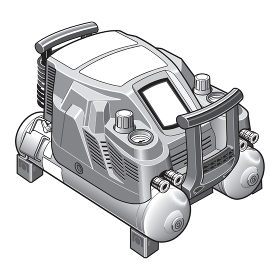
2. NAME OF PARTS Warning label Reduction valve adjustment handle (H) Control panel (Orange cap) (Front panel) Pressure-reduction High pressure air chuck (for valve adjustment handle tools) (L) (Yellow cap) Drain cock Power cord Pressure gauge for indicating the set reduction valve pressure (2 gauges) Power plug General-purpose air chuck (for regular... - Page 13 (2 (H) and (L). gauges) (24.5 bar maximum on the H side and 8.3 bar maximum on the L side.) High pressure air chuck (for MAX It connects the MAX air hose for the tools. tools) General-purpose air chuck (for reg- It connects the air hose for the general-pressure nailers.
- Page 14 Operating mode Pressure control range Application example ON pressure OFF pressure NORMAL MODE 25 bar 29 bar Joinery work by MAX tools, general-purpose nailers, etc. HIGH POWER 30 bar 34 bar Continuous surface fastening and the MODE like with MAX tools.
- Page 15 3. MACHINE OPERATING PROCE- DURE Inspection and checkup prior to oper- ation 2. Turn the power switch on while maintain- WARNING ing the drain cock fully open. The buzzer • Prior to use, check the bolts and nuts for sounds with a beep at the same time. loosening and the parts for missing one.
- Page 16 8. Discharge the compressed air by open- ing the drain cock somewhat. Make sure that the operation is resumed due to a de- crease in the pressure. CAUTION • As the pressure in the air tank increases due to the pressure characteristic of the pressure-reduction valve, the pressure can vary from the set supply pressure by as much as 2 bar.
-
Page 17: Operating Procedure
(Due to Characteris- tics of pressure-reduction valve respectively) • 2 pressure-reduction valves provided on this machine allow you to connect MAX and the general-purpose nailer or pneumatic tool. 1. Fully open the drain cock and turn the <Pressure-reduction valve H>... - Page 18 (air chuck). 4. Connect the high pressure hose to the high pressure air hose for MAX PowerLite tools to the high pressure air chuck on the H side of the pressure-reduction valve.
-
Page 19: Protective Device
4. PROTECTIVE DEVICE If internal heat builds up during operation due to clogging of the airflow orifice, if the machine is WARNING used in a highly heated environment or if an ab- normality occurs inside the machine, the thermal 3. If the protective device was activated protector for preventing burnout may be activat- when there were no apparent problems ed to stop the motor operation. -
Page 20: Abnormalities During Operation
5. ABNORMALITIES DURING OPERATION WARNING • If you detect any abnormalities, do not op- erate the compressor. If you encounter any of the following abnormal phenomena, turn off the power switch immedi- ately, disconnect the power plug from the outlet and send the machine to your dealer or author- ized service facility for checkups or repairs. -
Page 21: Buzzer Types
6. BUZZER TYPES In normal operation Buzzer sounds Symptom Actions taken At powering on A one-time short beep sound (Pi) When the operating mode is switched In cases of abnormal operation TEMPERATURE OR Buzzer sounds ELECTRICAL PROB- Cause Actions taken LEM LED ( LED) None... -
Page 22: Automatic Adjustment Of Operating Power (Inverter Control)
7. AUTOMATIC ADJUSTMENT 8. IN ORDER TO MAINTAIN OF OPERATING POWER (IN- PERFORMANCE VERTER CONTROL) Microcomputer-based inverter control is enabled on this machine in order to ensure the maximum utilization of the discharging performance. Ad- justment of the operating power is automatically continued until the pressure in the machine tank reaches the maximum level being set for the cur- rently set mode. - Page 23 3. Implement the machine inspection on a regular basis. The User is requested to implement cleaning and inspection of the machine in order to maintain its performance. Please do not hes- itate to let your dealer or authorized service facility inspect your machine. 4.
- Page 24 OSTSTRASSE 22, 40211 Camerastraat 19 DÜSSELDORF, GERMANY 1322 BB Almere The Netherlands TEL: +49-211-9365300 Phone: +31-36-546-9699 FAX: +49-211-93653017 FAX: +31-36-536-3985 www.max-ltd.co.jp/int/ (GLOBAL Site) www.max-europe.com (EUROPE Site) 4007917 081210-00/00 PRINTED IN JAPAN...
Need help?
Do you have a question about the powerlite AKHL1230E and is the answer not in the manual?
Questions and answers