
Related Manuals for Pentax EPK-p


Summary of Contents for Pentax EPK-p
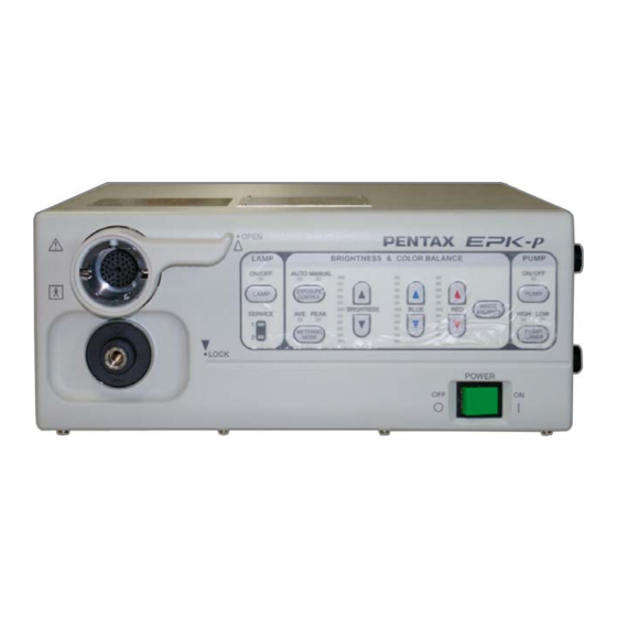
- Page 1 SERVICE MANUAL (Version 00) High cost performance Video Processor PENTAX EPK-p (type-C) MNL-049-00 / September 4, 2009...
-
Page 2: Table Of Contents
< CONTENTS> Page 1. Specifications ................2. General explanations ..............3. Functions..................Function diagram................ 4. Configuration (Main parts) ............5. Precaution ................6. Service 6.1 Lamp (LP1, LP2) replacement ..........6.2 Lamp harness (B510, 511) replacement ......6.3 Electrical adjustment 6.3.1 Iris adjustment ............... -
Page 3: Specifications
Illumination Color temperature 3,400K Iris control Automatic / Manual Brightness control Adjustable by +/- 5 steps each PENTAX Color Video K-series (K-series with Y/C output) Endoscope Scope compatibility With use of appropriate fiber scope video adapter PENTAX fiber scopes module. -
Page 4: General Explanations
2) Contrast> By changing the linearity of the Y luminance signal, contrast of the image can be changed in the EPK-p. Contrast changes cyclically by pressing “F9” key “Normal” > “High” > “Low”. 3) Starting lamp> The lamp can light by not merely pressing “LAMP” button but also setting the lamp start mode. - Page 5 • Image signal YCrCb is processed with enhancement, noise reduction, frozen image and Red and Blue gain in the FPGA. • Digital signal for pump transferred in serial from the CPU part is converted into analog signal and sent to Peripheral control part to control the pump. (3) CPU part >...
-
Page 6: Function Diagram
< EPK-p Type-C Function diagram > Power Noise Fuse (FU1) L Integrated power supply unit filter switch (PS1) (LF2) (SW1) Fuse (FU2) N 5V, +/-15VDC to Lamp 1 for Patient circuit patient circuit AC input (LP1) for Lamps Pump Iris motor... -
Page 7: Configuration (Main Parts)
4. Configuration (Main parts) Process Board (E700) Blower fan (FAN2) Pump (PM1) Rear fan (FAN1) Power switch Integrated power (SW1) Mechanical block supply unit (PS4) Interlock switch (SW2) Unit fan (FAN3) Scope lock sensor (PHC1) Pointing blinded parts Lamp selector (SW3) Photo-1 Front left side view Mechanical block Lamp No.1 (LP1) -
Page 8: Precaution
5. Precaution - Important 1) General You have to take utmost care to follow the general rules and practice for safety in servicing electrical medical equipment. 2) Power off before servicing For electrical safety, make sure to disconnect the power cable before opening the cover. 3) Route of electrical wire Be sure to keep the original routes of the electrical wires and the original positions of the cores. -
Page 9: Service
6. Service Note: 1) Refer to Photo-1, 2, Fig-1 for the location of the parts to be replaced. 2) If any Numbers shown in the photo, they correspond to the numbers of the items listed below. 6.1 Lamp (LP1, LP2) replacement A way of replacing the lamp bulb is described below. -
Page 10: Electrical Adjustment
6.3 Electrical adjustment Preparation Set a jumper to STB2 to disengage the lamp internal lock switch, and set Jig mode by putting a jumper to STB3. Refer to Photo-5. Note: When opening the cover, it is necessary to remove the screw which is available under the lamp house lid. 6.3.1 Iris adjustment (necessary when the iris unit or Process board was replaced) 6.3.1-1 Hole element current adjustment 1) Connect the probes of the meter to TP25(+) and TP26(common). -
Page 11: Pump Adjustment
Photo-7 Air flow & pressure meter 2) Turn on the power of the EPK-p and enter the key command “Ctrl + Alt + Shift + P” with the key board to show “Pump Level” menu on the monitor. Refer to Fig-3 below. -
Page 12: Electrical Safety Test
Important: After opening the cover of the unit for repair, the electrical safety test is indispensable. 7.1 Dielectric strength test Caution: 1) Be sure to keep away from the equipment while the high voltage is being applied to the EPK-p. 2) This test is one kind of destructive tests. Multiple tests may damage the EPK-p. -
Page 13: Leakage Current Test
2) Set the AC power line condition described in Table-3 depending on the test type and connect the AC cable to the EPK-p. 3) Apply 110% AC voltage, turn on the EPK-p and turn on the lamp and pump in high-mode. 4) Measure the leakage current value indicated on the meter and record it. -
Page 14: Trouble Shooting
8. Trouble shooting Symptom CHECK ACTION Check the fuses in the fuse box located above the AC inlet. If they have been brown, you need to find a part Fuse (FU1, FU2) that may cause the excessive load by disconnecting parts one by one. -
Page 15: Wiring Diagram
9. Wiring Diagram Power switch Noise filter B702-Br B704-Br B705-Br B703-Y/G B705-Blu B704-Blu B701-Blu Fuse FU1, 2 120V model FSL250V3.15A 230V model FSL250V1.6A Integrated power supply unit Brown Blue Lamp 2 for Lamp B511 (Black) for Patient circuit for Secondary circuit Pump Lamp 1 B510 (White)
Need help?
Do you have a question about the EPK-p and is the answer not in the manual?
Questions and answers