Table of Contents
Advertisement
Quick Links
Pos : 2 /D okumentati on allgemein/Ei nband/Ei nband H andbuch - Fronts eite 2015 - mit Doc Variabl en (Standar d) @ 9\mod_1285229289866_0.doc x @ 64941 @ @ 1
WAGO-I/O-System 750
Manual
750-370
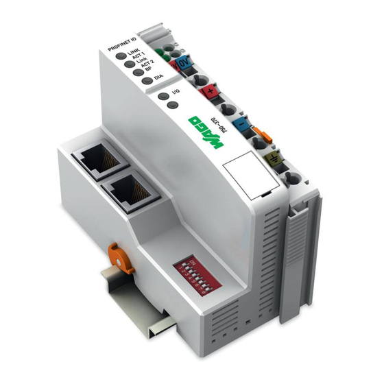
PROFINET IO Fieldbus Coupler
2-port; 100 Mbit/s; digital and analog signals
Version 2.0.0
Pos : 3 /Alle Serien (Allgemeine M odul e)/Hinweise z ur Dokumentation/Impres sum für Standardhandbüc her - allg. Angaben, Ansc hriften, Tel efonnummer n und E-Mail-Adres sen @ 3\mod_1219151118203_21.doc x @ 21060 @ @ 1
Advertisement
Chapters
Table of Contents

Related Manuals for WAGO 750-370


Summary of Contents for WAGO 750-370
- Page 1 Pos : 2 /D okumentati on allgemein/Ei nband/Ei nband H andbuch - Fronts eite 2015 - mit Doc Variabl en (Standar d) @ 9\mod_1285229289866_0.doc x @ 64941 @ @ 1 WAGO-I/O-System 750 Manual 750-370 PROFINET IO Fieldbus Coupler 2-port; 100 Mbit/s; digital and analog signals Version 2.0.0...
- Page 2 WAGO-I/O-System 750 750-370 PROFINET IO Fieldbus Coupler © 2016 by WAGO Kontakttechnik GmbH & Co. KG All rights reserved. WAGO Kontakttechnik GmbH & Co. KG Hansastraße 27 D-32423 Minden Phone: +49 (0) 571/8 87 – 0 Fax: +49 (0) 571/8 87 – 1 69 E-Mail: info@wago.com...
-
Page 3: Table Of Contents
2.1.1 Subject to Changes ................14 2.1.2 Personnel Qualifications ..............14 2.1.3 Use of the WAGO-I/O-SYSTEM 750 in Compliance with Underlying Provisions ..............14 2.1.4 Technical Condition of Specified Devices ......... 15 Safety Advice (Precautions) ..............16 System Description..................18 Manufacturing Number ................ - Page 4 Table of Contents WAGO-I/O-System 750 750-370 PROFINET IO Fieldbus Coupler 4.1.2 PROFINET IO Properties..............42 4.1.3 Implemented Protocols and Services..........43 4.1.4 Supported Profiles for PROFINET IO ..........44 View ......................45 Connectors ....................47 4.3.1 Device Supply ..................47 4.3.2...
- Page 5 WAGO-I/O-System 750 Table of Contents 750-370 PROFINET IO Fieldbus Coupler Configuration Limits ................80 7.5.1 Minimum Configuration ..............80 7.5.2 Maximum Configuration ..............80 Flexible Configuration of Digital I/O Modules ........81 7.6.1 Packaging Information from Digital Input and Output Modules ..81 7.6.1.1...
- Page 6 Table of Contents WAGO-I/O-System 750 750-370 PROFINET IO Fieldbus Coupler 10.3.2 Structure of the Standardized Diagnosis Data Sets ......128 Fieldbus Communication ................ 129 11.1 Standard ETHERNET Protocols ............129 11.1.1 IP, TCP and HTTP ................129 11.1.2 DCP ....................129 11.1.3...
- Page 7 WAGO-I/O-System 750 Table of Contents 750-370 PROFINET IO Fieldbus Coupler 14.1.6.3 Distance and Angle Measurement Modules ........ 165 14.1.6.4 Serial Interfaces ................166 14.1.6.5 DC-Drive Controller ..............167 14.1.6.6 RTC Module ................167 14.1.6.7 DALI/DSI Master and DALI Multi-Master Modules ....168 14.1.6.8...
-
Page 8: Notes About This Documentation
Validity of this Documentation Pos : 10 /Serie 750 ( WAGO-I/O-SYST EM)/Hi nweis e z ur D okumentati on/Gültigkeits bereic hGültig keitsbereic h D okumentati on Koppl er/Contr oller 750- xxxx, ohne Variantenangabe @ 14\mod_1358944039400_21.doc x @ 109362 @ @ 1 This documentation is only applicable to the “PROFINET IO Fieldbus Coupler”... -
Page 9: Symbols
Notes about this Documentation 750-370 PROFINET IO Fieldbus Coupler Pos : 12.3 /All e Seri en ( Allgemei ne Module)/Ü bers chriften für alle Serien/Hinweis e z ur Dokumentation/Symbol e - Ü bersc hrift 2 @ 13\mod_1351068042408_21.doc x @ 105270 @ 2 @ 1 Symbols Pos : 12.4.1 /All e Serien ( Allgemei ne Module)/Wic htige Erläuterungen/Sicherheits- und sons tige Hinweis e/Gefahr/Gefahr: _War nung vor Personenschäden allgemei n_ - Erl äuter ung @ 13\mod_1343309450020_21.doc x @ 101029 @ @ 1... -
Page 10: 750-370 Profinet Io Fieldbus Coupler
Notes about this Documentation WAGO-I/O-System 750 750-370 PROFINET IO Fieldbus Coupler Additional Information: Refers to additional information which is not an integral part of this documentation (e.g., the Internet). Pos : 12.5 /Dokumentation allgemei n/Glieder ungs elemente/---Seitenwechs el--- @ 3\mod_1221108045078_0.doc x @ 21810 @ @ 1 Manual Version 2.0.0... -
Page 11: Number Notation
Keys are marked with bold letters in square brackets. e.g.: [F5] Pos : 13 /Serie 750 ( WAGO-I/O-SYST EM)/F unktions beschr eibung/Speic herfunktion/F eldbus kommuni kation/PROFIN ET/PROFINET-Abkürz ungen (750- 370) @ 24\mod_1444976512939_21.doc x @ 193738 @ 2 @ 1 Manual... -
Page 12: Abbreviations And Terms
Notes about this Documentation WAGO-I/O-System 750 750-370 PROFINET IO Fieldbus Coupler Abbreviations and Terms Table 3: Abbreviations and Terms used in this Manual Abbreviation/ Explanation Description Term ALCR Alarm CR Acyclic PROFINET IO real-time channel for transmission of alarm messages. -
Page 13: 750-370 Profinet Io Fieldbus Coupler
WAGO-I/O-System 750 Notes about this Documentation 750-370 PROFINET IO Fieldbus Coupler Table 3: Abbreviations and Terms used in this Manual Abbreviation/ Explanation Description Term iPar Individual Individual parameterization of safety-related parameters for Parameter fail-safe PROFIsafe V2 I/O modules. The standardized Individual Parameter Server (iPar Server) automatically restores the parameterization when replacing components. -
Page 14: Important Notes
PLC programming. Pos : 16.5 /Serie 750 (WAGO-I/O-SYST EM)/Wic htige Erläuterungen/Bes timmungsgemäß e Verwendung Bes ti mmungsgemäße Verwendung 750-xxxx - Ü berschrift 3 und Inhal t @ 3\mod_1224064151234_21.doc x @ 24070 @ 3 @ 1 2.1.3... -
Page 15: Technical Condition Of Specified Devices
Important Notes 750-370 PROFINET IO Fieldbus Coupler Appropriate housing (per 94/9/EG) is required when operating the WAGO-I/O- SYSTEM 750 in hazardous environments. Please note that a prototype test certificate must be obtained that confirms the correct installation of the system in a housing or switch cabinet. -
Page 16: Safety Advice (Precautions)
Pos : 16.10.2 /Serie 750 ( WAGO-I/O- SYST EM)/Wic htig e Erl äuter ung en/Sic her hei ts- und s onstige Hi nweise/Gefahr/Gefahr: Ei nbau 0750- xxxx nur i n Gehäus en, Sc hränken oder el ektrisc hen Betriebsräumen! @ 6\mod_1260180556692_21.doc... -
Page 17: 750-370 Profinet Io Fieldbus Coupler
WAGO-I/O-System 750 Important Notes 750-370 PROFINET IO Fieldbus Coupler Do not use any contact spray! Do not use any contact spray. The spray may impair contact area functionality in connection with contamination. Pos : 16.11.5 /Alle Serien (Allgemeine D okumente) (Allgemeine M odul e)/Wichtige Erläuter ungen/Sic herheits hinweise/Ac htung/Ac htung: Verpol ung ver mei den! @ 6\mod_1260184045744_21.doc x @ 46767 @ @ 1... -
Page 18: System Description
IEC 61131-3. Pos : 18.4 /Serie 750 (WAGO-I/O-SYST EM)/Systembesc hrei bung/Ger ät und Sys tem/Systembesc hrei bung - Kommuni kati on Kl emmenbus , LEDs , 3-Leitertec hni k @ 3\mod_1231493520906_21.doc x @ 25877 @ @ 1 I/O modules for diverse digital and analog I/O signals as well as special functions can be connected to the fieldbus coupler/controller. -
Page 19: Manufacturing Number
Pos : 18.7.2 /Serie 750 (WAGO-I/O-SYST EM)/Gerätebesc hrei bung/Bedruc kung/Fertig ungs nummer 750- xxxx - Abbil dung und Erläuterung @ 24\mod_1443678328855_21.doc x @ 192638 @ @ 1 Figure 2: Marking Area for Serial Numbers There are two serial numbers in two rows in the side marking. -
Page 20: 750-370 Profinet Io Fieldbus Coupler
The first three bytes identify the manufacturer (e.g. 00:30 DE for WAGO). The second 3 bytes comprise the unique serial number of the hardware. Pos : 18.9 /Dokumentation allgemei n/Glieder ungs elemente/---Seitenwechs el--- @ 3\mod_1221108045078_0.doc x @ 21810 @ @ 1 Manual Version 2.0.0... -
Page 21: Component Update
The original manufacturing information on the device's housing remains unchanged. Pos : 18.11 /Serie 750 ( WAGO-I/O-SYST EM)/Systembesc hrei bung/Gerät und System/Lagerung, Kommissi onierung und Tr ansport @ 3\mod_1225446600609_21.doc x @ 24897 @ 2 @ 1 Storage, Assembly and Transport Whenever possible, the components are to be stored in their original packaging. -
Page 22: Assembly Guidelines/Standards
System Description WAGO-I/O-System 750 750-370 PROFINET IO Fieldbus Coupler Pos : 18.13 /Serie 750 ( WAGO-I/O-SYST EM)/Systembesc hrei bung/Gerät und System/Aufbaurichtli nien und N or men @ 3\mod_1231311929250_21.doc x @ 25820 @ 2 @ 1 Assembly Guidelines/Standards • DIN 60204 Electrical equipment of machines •... -
Page 23: Power Supply
Pos : 18.15.3 /Serie 750 ( WAGO-I/O- SYST EM)/Sys tembesc hrei bung/Vers orgung/Potenti altrennung - Bil d (Standar d + er weiterter EC O) @ 3\mod_1232950095187_21.doc x @ 26740 @ @ 1 Figure 3: Isolation for Fieldbus Couplers/Controllers (Example) Pos : 18.15.4 /D okumentati on allgemein/Gli ederungsel emente/---Seitenwec hs el--- @ 3\mod_1221108045078_0.doc x @ 21810 @ @ 1... -
Page 24: System Supply
Pos : 18.15.7 /Serie 750 ( WAGO-I/O- SYST EM)/Sys tembesc hrei bung/Vers orgung/Systemversorgung - Ans chl uss - Sys temvers orgung ( Standar d + er wei terter ECO) @ 3\mod_1232950104031_21.doc x @ 26776 @ @ 1 Figure 4: System Supply via Fieldbus Coupler/Controller (left) and via Internal System Supply Module (right) Table 4: Legend for Figure “System Supply via Fieldbus Coupler/Controller (left) and via Internal... -
Page 25: Dimensioning
Figure 5: System Voltage for Standard Couplers/Controllers and Extended ECO Couplers Pos : 18.15.10 /Seri e 750 ( WAGO-I/O-SYSTEM)/Systembes chr eibung/Versorgung/Systemvers orgung - Ansc hlus s - Hi nweis : Gl eichz. R üc ks etzen aller Vers orgungsmodul e @ 3\mod_1232950097906_21.doc x @ 26760 @ @ 1... -
Page 26: 750-370 Profinet Io Fieldbus Coupler
Pos : 18.15.13 /Seri e 750 ( WAGO-I/O-SYSTEM)/Systembes chr eibung/Versorgung/Beis piel: @ 3\mod_1232630417843_21.doc x @ 26605 @ @ 1 Example: Pos : 18.15.14 /Seri e 750 ( WAGO-I/O-SYSTEM)/Systembes chr eibung/Versorgung/Systemvers orgung - Ausl egung - Beispi el 1 (Standar d) @ 3\mod_1232950106875_21.doc x @ 26792 @ @ 1 Calculating the current consumption on the fieldbus coupler:... -
Page 27: 750-370 Profinet Io Fieldbus Coupler
(87 % Efficiency of the power supply at nominal load 24 V) Pos : 18.15.20 /Seri e 750 ( WAGO-I/O-SYSTEM)/Systembes chr eibung/Versorgung/Systemvers orgung - Ausl egung - Hi nweis: Bei Test der Str omaufnahme Ausg äng e akti vi eren @ 3\mod_1232950110750_21.doc x @ 26812 @ @ 1... -
Page 28: Field Supply
Pos : 18.15.24 /Seri e 750 ( WAGO-I/O-SYSTEM)/Systembes chr eibung/Versorgung/F eldversorgung - Ans chl uss - Ei nspeis ung fel dsei tig (Standard + er weiterter ECO) @ 3\mod_1232950087703_21.doc x @ 26712 @ @ 1 The fieldbus coupler/controller provides field side power (DC 24 V). -
Page 29: Table 6: Legend For Figure "Field Supply For Standard Couplers/Controllers And Extended Eco Couplers
Pos : 18.15.30 /Seri e 750 ( WAGO-I/O-SYSTEM)/Systembes chr eibung/Versorgung/F eldversorgung - Ans chl uss - 2 Hi nweise: Potential neu ei ns peis en + Dis tanz kl emme @ 3\mod_1232950091343_21.doc x @ 26724 @ @ 1... -
Page 30: Fusing
System Description WAGO-I/O-System 750 750-370 PROFINET IO Fieldbus Coupler Pos : 18.15.32 /Seri e 750 ( WAGO-I/O-SYSTEM)/Systembes chr eibung/Versorgung/F eldversorgung - Absic herung @ 3\mod_1232950081500_21.doc x @ 26692 @ 4 @ 1 3.6.3.2 Fusing Internal fusing of the field supply is possible for various field voltages via an appropriate power supply module. -
Page 31: Figure 8: Removing The Fuse Carrier
WAGO-I/O-System 750 System Description 750-370 PROFINET IO Fieldbus Coupler Figure 8: Removing the Fuse Carrier Lifting the cover to the side opens the fuse carrier. Figure 9: Opening the Fuse Carrier Figure 10: Changing the Fuse After changing the fuse, the fuse carrier is pushed back into its original position. -
Page 32: Figure 11: Fuse Modules For Automotive Fuses, Series 282
System Description WAGO-I/O-System 750 750-370 PROFINET IO Fieldbus Coupler Alternatively, fusing can be done externally. The fuse modules of the WAGO series 281 and 282 are suitable for this purpose. Figure 11: Fuse Modules for Automotive Fuses, Series 282 Figure 12: Fuse Modules for Automotive Fuses, Series 2006... -
Page 33: Supplementary Power Supply Regulations
WAGO-I/O-System 750 System Description 750-370 PROFINET IO Fieldbus Coupler Pos : 18.15.34 /Seri e 750 ( WAGO-I/O-SYSTEM)/Systembes chr eibung/Versorgung/Ergänz ende Eins peisungs vors chriften (Standar d) @ 3\mod_1232950080218_21.doc x @ 26684 @ 3 @ 1 3.6.4 Supplementary Power Supply Regulations The WAGO-I/O-SYSTEM 750 can also be used in shipbuilding or offshore and onshore areas of work (e. -
Page 34: Supply Example
Figure 16: Supply Example for Standard Couplers/Controllers Pos : 18.15.38 /Seri e 750 ( WAGO-I/O-SYSTEM)/Systembes chr eibung/Versorgung/Vers orgungs beis piel - Legende zu Abbil dung "Vers orgungs beis pi el für F eldbus koppler/-c ontroller" @ 16\mod_1375881755097_21.doc x @ 128220 @ @ 1 Manual Version 2.0.0... -
Page 35: Table 9: Legend For Figure "Supply Example For Fieldbus Coupler/Controller
WAGO-I/O-System 750 System Description 750-370 PROFINET IO Fieldbus Coupler Table 9: Legend for Figure “Supply Example for Fieldbus Coupler/Controller” Pos. Description Power Supply on fieldbus coupler/controller via external Supply Module Power Supply with optional ground Internal System Supply Module Separation module recommended... -
Page 36: Power Supply Unit
System Description WAGO-I/O-System 750 750-370 PROFINET IO Fieldbus Coupler Pos : 18.15.40 /Seri e 750 ( WAGO-I/O-SYSTEM)/Systembes chr eibung/Versorgung/Netzger äte @ 3\mod_1232950093484_21.doc x @ 26728 @ 3 @ 1 3.6.6 Power Supply Unit The WAGO-I/O-SYSTEM 750 requires a 24 VDC voltage (system supply). -
Page 37: Grounding
WAGO-I/O-System 750 System Description 750-370 PROFINET IO Fieldbus Coupler Pos : 18.15.42 /Seri e 750 ( WAGO-I/O-SYSTEM)/Systembes chr eibung/Versorgung/Er dung @ 3\mod_1231246555687_21.doc x @ 25802 @ 23443 @ 1 Grounding 3.7.1 Grounding the DIN Rail 3.7.1.1 Framework Assembly When setting up the framework, the carrier rail must be screwed together with the electrically conducting cabinet or housing frame. -
Page 38: Grounding Function
System Description WAGO-I/O-System 750 750-370 PROFINET IO Fieldbus Coupler 3.7.2 Grounding Function The grounding function increases the resistance against electro-magnetic interferences. Some components in the I/O system have a carrier rail contact that dissipates electro-magnetic interferences to the carrier rail. -
Page 39: Shielding
WAGO-I/O-System 750 System Description 750-370 PROFINET IO Fieldbus Coupler Pos : 18.15.44 /Seri e 750 ( WAGO-I/O-SYSTEM)/Systembes chr eibung/Versorgung/Schir mung @ 3\mod_1231251994828_21.doc x @ 25813 @ 23333 @ 1 Shielding 3.8.1 General Use of shielded cables reduces electromagnetic interference and thus increases signal quality. -
Page 40: Signal Lines
3.8.4 WAGO Shield Connecting System The WAGO shield connecting system consists of shield clamping saddles, busbars and various mounting carriers. These components can be used to achieve many different configurations. -
Page 41: Device Description
Device Description Pos : 21.1 /Serie 750 (WAGO-I/O-SYST EM)/Ger ätebesc hrei bung/Ei nlei tung/F eldbus koppl er/-c ontroller/Einl eitender Text/D er F eldbus koppler 750- 0370 @ 15\mod_1371020919059_21.doc x @ 122550 @ 23 @ 1 The fieldbus coupler 750-370 connects the WAGO-I/O-SYSTEM 750/753 to PROFINET IO, the open, real-time industrial ETHERNET automation standard. -
Page 42: Fieldbus Coupler Properties
Configurable substitute values for each output channel in the event of failure Pos : 21.2 /Serie 750 (WAGO-I/O-SYST EM)/Ger ätebesc hrei bung/Ei nlei tung/F eldbus koppl er/-c ontroller/Einl eitender Text/PROF INET IO-Koppler Eigensc haften und Mengenger üst - Ü bersicht 750-370 @ 23\mod_1435752767522_21.doc x @ 185053 @ 3 @ 1 4.1.2... -
Page 43: Implemented Protocols And Services
Pos : 21.3 /Serie 750 (WAGO-I/O-SYST EM)/Ger ätebesc hrei bung/Ei nlei tung/F eldbus koppl er/-c ontroller/Einl eitender Text/U nterstütz te Pr otokoll e und Profil e für PROF INET IO 750-370 @ 23\mod_1435752954285_21.doc x @ 185057 @ 33 @ 1... -
Page 44: Supported Profiles For Profinet Io
Device Description WAGO-I/O-System 750 750-370 PROFINET IO Fieldbus Coupler 4.1.4 Supported Profiles for PROFINET IO The fieldbus coupler also supports the following profiles in conjunction with the particular I/O modules: • PROFIsafe V2.4 • iPar-Server V1.0.1 More information on supported profiles! You can learn more about supported profiles in the “Function Description”... -
Page 45: View
View Pos : 24.1 /Serie 750 (WAGO-I/O-SYST EM)/Ger ätebesc hrei bung/Ansic ht/Fel dbus koppl er/-contr oller/Leg ende/Ansic ht - allg. Einl eitung für PROF INET IO- Koppler ( 750-370) @ 22\mod_1429188384907_21.doc x @ 180368 @ @ 1 The view shows three different units of the device: •... -
Page 46: Table 13: Legend For Figure "View Fieldbus Coupler Profinet Io
Pos : 24.4 /Serie 750 (WAGO-I/O-SYST EM)/Ger ätebesc hrei bung/Ansic ht/Fel dbus koppl er/-contr oller/Leg ende/Ansic ht - Legende zur Ansicht PROFIN ET IO- Koppl er (750-370) – Tabell enkopf und Nr: 1 @ 22\mod_1429260906746_21.doc... -
Page 47: Connectors
Connectors Pos : 27 /Serie 750 ( WAGO-I/O-SYST EM)/Ger ätebesc hrei bung/Schematisc he Sc haltbil der/Fel dbus koppl er/-contr oller/Ger äteei nspeis ung - Ü berschrift 3 und Einl eitung 750-0xxx @ 5\mod_1245074097866_21.doc x @ 35349 @ 3 @ 1 4.3.1... -
Page 48: Fieldbus Connection
Pos : 30.3 /Serie 750 (WAGO-I/O-SYST EM)/Ger ätebesc hrei bung/Ansc hl üsse/F eldbus koppler/-c ontroller/Di e RJ- 45-Buchs en si nd ents prechend den Vorgaben für 100Bas eT X bes chaltet. (750- 354) @ 7\mod_1273051805011_21.doc... -
Page 49: Display Elements
Pos : 33.4 /Serie 750 (WAGO-I/O-SYST EM)/Ger ätebesc hrei bung/Anz eigeelemente/Fel dbus koppl er/-contr oller/Legende/Anz eigeelemente - F eldbus status PROFIN ET- basi ert, spezifis cher T abellenteil 'LIN K ACT 1,2' @ 23\mod_1439199059516_21.doc x @ 187718 @ @ 1... -
Page 50: 750-370 Profinet Io Fieldbus Coupler
Device Description WAGO-I/O-System 750 750-370 PROFINET IO Fieldbus Coupler More information about the LED Signaling Read the detailed description for the evaluation of the displayed LED state in the section “Diagnostics” > … > “LED Signaling”. Pos : 34 /D okumentation allgemei n/Glieder ungs elemente/---Seitenwechs el--- @ 3\mod_1221108045078_0.doc x @ 21810 @ @ 1 Manual Version 2.0.0... -
Page 51: Operating Elements
Pos : 36.1 /Serie 750 (WAGO-I/O-SYST EM)/Ger ätebesc hrei bung/Bedienel emente/F el dbus koppl er/-contr oller/Ser vic e-Sc hnitts tell e - Ü bersc hrift 3, und allgemei ne Ei nleitung @ 4\mod_1239105167430_21.doc x @ 30221 @ 3 @ 1... -
Page 52: Dip Switch
DIP Switch Pos : 38.2 /Serie 750 (WAGO-I/O-SYST EM)/Ger ätebesc hrei bung/Bedienel emente/F el dbus koppl er/-contr oller/DIP-Sc halter-Bild ( 8 ... 1 von oben nac h unten) Bilduntersc hrift: DIP-Sc halter @ 15\mod_1369661277690_21.doc x @ 120600 @ @ 1 Figure 26: DIP Switch Pos : 38.3 /Serie 750 (WAGO-I/O-SYST EM)/Ger ätebesc hrei bung/Bedienel emente/F el dbus koppl er/-contr oller/Adr ess wahlsc halter PR OFIN ET: D er Adr ess wahls chalter di ent z ur opt. -
Page 53: Table 19: Dip Switch - Explanation Of The 8 Slide Switches
No. 7 determines the fixed part of the device name. In the ‘OFF’ position, the device uses the character string “wago-750-370” as the fixed part of the device name. In the ‘ON’ position, the character string “wagox750x370” is used. -
Page 54: 750-370 Profinet Io Fieldbus Coupler
Device Description WAGO-I/O-System 750 750-370 PROFINET IO Fieldbus Coupler The device name “wagox750x370x11” results from the example DIP switch setting. Assigning the address via DCP! The station is normally named as part of the configuration by assigning the device name via DCP. -
Page 55: Technical Data
Pos : 40 /All e Seri en (Allgemei ne Module)/Ü berschriften für alle Serien/Gerätebesc hreibung/Technisc he Daten - Ü berschrift 2 @ 3\mod_1232967587687_21.doc x @ 26924 @ 2 @ 1 Technical Data Pos : 41 /Serie 750 ( WAGO-I/O-SYST EM)/Ger ätebesc hrei bung/T echnisc he Daten/F el dbus koppl er/-contr oller/T ec hnisc he D aten 750- 0370 @ 22\mod_1429611431730_21.doc x @ 180808 @ 3333 @ 1 4.6.1 Device Data Table 21: Technical Data –... -
Page 56: System Data
Connection Type Pos : 42.2 /Serie 750 (WAGO-I/O-SYST EM)/Ger ätebesc hrei bung/T echnisc he Daten/T ec hnische D aten Verdr ahtungs ebene CC - 0,08 bis 2,5mm2 @ 17\mod_1380121238809_21.doc x @ 132780 @ @ 1 Table 25: Technical Data – Field Wiring ®... -
Page 57: Climatic Environmental Conditions
Pos : 43 /Serie 750 ( WAGO-I/O-SYST EM)/Ger ätebesc hrei bung/T echnisc he Daten/Kli matische U mg ebungs bedi ngungen/Technisc he Daten Klimat. U mgebungs bed. ohne er w. Temp. 0...55°C/-25...+85°C @ 5\mod_1247657968368_21.doc x @ 37603 @ 3 @ 1... -
Page 58: Approvals
750 > System Description. Pos : 47 /Serie 750 ( WAGO-I/O-SYST EM)/Ger ätebesc hrei bung/Z ulass ungen/Allgemei n/Z ulass ungen F Bkoppler/-c ontroller 750- xxxx Allgemei n, ohne Vari antenang abe - Einl eitung @ 5\mod_1245241119092_21.doc x @ 35493 @ @ 1... -
Page 59: Standards And Guidelines
Standards and Guidelines Pos : 54 /Serie 750 ( WAGO-I/O-SYST EM)/Ger ätebesc hrei bung/N ormen und Ric htlini en/EM V-Nor men FBkoppl er/-c ontr oller 750- xxxx, ohne Vari antenangabe - Einl eitung @ 5\mod_1245244309850_21.doc x @ 35512 @ @ 1... -
Page 60: Mounting
Pos : 59 /All e Seri en (Allgemei ne Module)/Ü berschriften für alle Serien/Monti eren/M ontier en - Übersc hrift 1 @ 3\mod_1225446744750_21.doc x @ 24900 @ 1 @ 1 Mounting Pos : 60.1 /Serie 750 (WAGO-I/O-SYST EM)/M ontieren/D emontieren/Einbaul age @ 3\mod_1225446818312_21.doc x @ 24903 @ 2 @ 1 Installation Position Along with horizontal and vertical installation, all other installation positions are allowed. -
Page 61: Overall Configuration
WAGO-I/O-System 750 Mounting 750-370 PROFINET IO Fieldbus Coupler Pos : 60.3 /Serie 750 (WAGO-I/O-SYST EM)/M ontieren/D emontieren/Gesamtaus bau @ 3\mod_1231764099468_21.doc x @ 25940 @ 2 @ 1 Overall Configuration The maximum total length of a fieldbus node without fieldbus coupler/controller is 780 mm including end module. -
Page 62: Mounting Onto Carrier Rail
Mounting WAGO-I/O-System 750 750-370 PROFINET IO Fieldbus Coupler Pos : 60.5 /Serie 750 (WAGO-I/O-SYST EM)/M ontieren/D emontieren/M ontage auf Tr agschi ene @ 3\mod_1225447227234_21.doc x @ 24906 @ 233 @ 1 Mounting onto Carrier Rail 5.3.1 Carrier Rail Properties All system components can be snapped directly onto a carrier rail in accordance with the European standard EN 50022 (DIN 35). -
Page 63: Wago Din Rail
35 × 15; 2.3 mm; copper; unslotted 210-196 35 × 8.2; 1.6 mm; aluminum; unslotted Pos : 60.6 /Serie 750 (WAGO-I/O-SYST EM)/M ontieren/D emontieren/Abstände @ 3\mod_1225448283750_21.doc x @ 24920 @ 2 @ 1 Spacing The spacing between adjacent components, cable conduits, casing and frame sides must be maintained for the complete fieldbus node. -
Page 64: Mounting Sequence
Pos : 60.10 /Serie 750 ( WAGO-I/O-SYST EM)/Wichtig e Erl äuter ung en/Sic her hei ts- und s onstige Hinweise/Ac htung/Ac htung: Bus kl emmen nur in vorges ehener Rei henfolge stec ken! @ 6\mod_1256194177073_21.doc... -
Page 65: Inserting And Removing Devices
Mounting 750-370 PROFINET IO Fieldbus Coupler Pos : 60.13 /Serie 750 ( WAGO-I/O-SYST EM)/Monti eren/D emonti eren/Ger äte ei nfügen und entfernen - Ü bersc hrift 2 @ 3\mod_1231768483250_21.doc x @ 25950 @ 2 @ 1 Inserting and Removing Devices Pos : 60.14 /Alle Serien (Allgemeine M odul e)/Wichtige Erläuterungen/Sic herheits- und s onstige Hinweise/Achtung/Ac htung: Ar beiten an Geräten nur spannungsfrei durchführen! @ 6\mod_1256193963573_21.doc x @ 43426 @ @ 1... -
Page 66: Inserting The Fieldbus Coupler/Controller
Mounting WAGO-I/O-System 750 750-370 PROFINET IO Fieldbus Coupler Pos : 60.16 /Serie 750 ( WAGO-I/O-SYST EM)/Monti eren/D emonti eren/F eldbus koppler/-c ontroll er ei nfügen @ 3\mod_1234168173031_21.doc x @ 27456 @ 3 @ 1 5.6.1 Inserting the Fieldbus Coupler/Controller When replacing the fieldbus coupler/controller for an already available fieldbus coupler/controller, position the new fieldbus coupler/controller so that the tongue and groove joints to the subsequent I/O module are engaged. -
Page 67: Removing The Fieldbus Coupler/Controller
750-370 PROFINET IO Fieldbus Coupler Figure 30: Release Tab ECO Coupler Pos : 60.20 /Serie 750 ( WAGO-I/O-SYST EM)/Monti eren/D emonti eren/F eldbus koppler/-c ontroll er entfer nen @ 4\mod_1239169358453_21.doc x @ 30330 @ 3 @ 1 5.6.2 Removing the Fieldbus Coupler/Controller Use a screwdriver blade to turn the locking disc until the nose of the locking disc no longer engages behind the carrier rail. -
Page 68: Inserting The I/O Module
Mounting WAGO-I/O-System 750 750-370 PROFINET IO Fieldbus Coupler Pos : 60.22 /Serie 750 ( WAGO-I/O-SYST EM)/Monti eren/D emonti eren/Bus kl emme einfügen @ 3\mod_1231769726703_21.doc x @ 25989 @ 3 @ 1 5.6.3 Inserting the I/O Module Position the I/O module so that the tongue and groove joints to the fieldbus coupler/controller or to the previous or possibly subsequent I/O module are engaged. -
Page 69: Removing The I/O Module
WAGO-I/O-System 750 Mounting 750-370 PROFINET IO Fieldbus Coupler Pos : 60.24 /Serie 750 ( WAGO-I/O-SYST EM)/Monti eren/D emonti eren/Bus kl emme entfer nen @ 4\mod_1239169375203_21.doc x @ 30334 @ 3 @ 1 5.6.4 Removing the I/O Module Remove the I/O module from the assembly by pulling the release tab. -
Page 70: Connect Devices
Pos : 63.4 /Serie 750 (WAGO-I/O-SYST EM)/Wic htige Erläuterungen/Sicherheits- und sonstig e Hinweis e/Achtung/Achtung: ESD - Auf g ute Erdung der U mgebung ac hten! @ 7\mod_1266318538667_21.doc x @ 50708 @ @ 1 Ensure that the environment is well grounded! The devices are equipped with electronic components that may be destroyed by electrostatic discharge. -
Page 71: Power Contacts/Field Supply
Figure 35: Example for the Arrangement of Power Contacts Pos : 63.9 /Serie 750 (WAGO-I/O-SYST EM)/Wic htige Erläuterungen/Sicherheits- und sonstig e Hinweis e/Hinweis/Hi nweis: F eldbus knoten mit s mar tDESIGN ER konfiguri eren und überpr üfen @ 6\mod_1256193439792_21.doc x @ 43420 @ @ 1 Field bus node configuration and test via smartDESIGNER ®... -
Page 72: Connecting A Conductor To The Cage Clamp
WAGO-I/O-System 750 750-370 PROFINET IO Fieldbus Coupler Pos : 63.11 /Serie 750 ( WAGO-I/O-SYST EM)/Ansc hließ en/Leiter an CAGE CLAMP ansc hließ en (allgemein) - Ü berschrift 2 und T ext @ 3\mod_1225448660171_21.doc x @ 24928 @ 2 @ 1 ®... -
Page 73: Function Description
Function Description Pos : 66.1 /Serie 750 (WAGO-I/O-SYST EM)/F unktions beschr eibung/Funkti onsbesc hrei bung 750-370 - T eil 1 - (Auflistung des Kapitels) @ 22\mod_1430919965842_21.doc x @ 181795 @ @ 1 This section describes the essential functions of the fieldbus coupler. -
Page 74: Device Start-Up And Initialization
750-370 PROFINET IO Fieldbus Coupler Pos : 66.3 /Serie 750 (WAGO-I/O-SYST EM)/F unktions beschr eibung/Funkti onsbesc hrei bung Stations hochl auf- und Initi alisierung 750-370,-375, - 377 - T eil 1.1 @ 15\mod_1370510165464_21.doc x @ 122000 @ 2 @ 1 Device Start-Up and Initialization After a restart the fieldbus coupler does several hardware tests, e.g. -
Page 75: Switch Port Settings
750-370 PROFINET IO Fieldbus Coupler Pos : 66.6 /Serie 750 (WAGO-I/O-SYST EM)/F unktions beschr eibung/Funkti onsbesc hrei bung 750-370 - T eil 2 (Identifi k.- und Wartungsd.sätze I&M) @ 23\mod_1433153471922_21.doc x @ 183132 @ 22 @ 1 Switch Port Settings... -
Page 76: Process Data Architecture
Pos : 66.9.3 /Serie 750 (WAGO-I/O-SYST EM)/F unktions beschr eibung/Prozes sabbil d/Infor mation: Anzahl der Ei n- und Ausg angs bits bz w. -bytes [...] entnehmen Si e Bus kl emmenbeschr eibung @ 6\mod_1256034203734_21.doc x @ 43146 @ @ 1... -
Page 77: Figure 38: Allocation Of The Input And Output Data
Pos : 66.9.8 /Serie 750 (WAGO-I/O-SYST EM)/F unktions beschr eibung/Prozes sabbil d/Infor mation: Weitere Infor mati onen z u Pr oz ess datenbegleitern und Konfigur ationsgrenz en! @ 19\mod_1403788580674_21.doc x @ 156798 @ @ 1 Manual Version 2.0.0... -
Page 78: Process Data Qualifiers In Telegrams For Profinet Io
“Configuration limits” section. Pos : 66.9.9 /Serie 750 (WAGO-I/O-SYST EM)/F unktions beschr eibung/Prozes sabbil d/Proz ess datenbeglei ter i n PROF INET IO-T elegrammen @ 15\mod_1367500677656_21.doc x @ 118398 @ 3444 @ 1 7.4.2 Process Data Qualifiers in Telegrams for PROFINET IO 7.4.2.1... -
Page 79: Table 32: Example 2 For Process Data Qualifiers For 2-Channel Digital Output
WAGO-I/O-System 750 Function Description 750-370 PROFINET IO Fieldbus Coupler Example 2: • Process data qualifiers for 2-channel digital output modules with diagnostics. Table 32: Example 2 for Process Data Qualifiers for 2-Channel Digital Output Modules with Diagnostics Telegram direction PNIO submodule IOD ... -
Page 80: Configuration Limits
WAGO-I/O-System 750 750-370 PROFINET IO Fieldbus Coupler Pos : 66.11 /Serie 750 ( WAGO-I/O-SYST EM)/Funkti onsbesc hrei bung/F unktions besc hreibung 750-370 - Teil 3 ( Konfiggrenzen, etc.) @ 23\mod_1436187544198_21.doc x @ 185308 @ 23323444 @ 1 Configuration Limits 7.5.1... -
Page 81: Flexible Configuration Of Digital I/O Modules
WAGO-I/O-System 750 Function Description 750-370 PROFINET IO Fieldbus Coupler Flexible Configuration of Digital I/O Modules 7.6.1 Packaging Information from Digital Input and Output Modules Digital input modules and/or digital output modules occupy a data volume of 1 or 2 bits per channel in the process image. Depending on the number of channels, the scope of the process data of the respective I/O modules ranges from 2 bits to 2 bytes. -
Page 82: Rules For Packaging Digital Information
Function Description WAGO-I/O-System 750 750-370 PROFINET IO Fieldbus Coupler Submodule types that allocate no data If data volumes larger than actually required to represent the physical channels are always used for digital I/O modules, data processing is very inefficient as data without any actual information also has to be transmitted. -
Page 83: Example Of Packaging Digital Information
WAGO-I/O-System 750 Function Description 750-370 PROFINET IO Fieldbus Coupler • When assigning, only I/O modules with digital input and output data are taken into account. I/O modules with analog input/output data are ignored even when physically between the digital input/output data according to the configuration. -
Page 84: Possible Errors When Packaging Digital Information
Function Description WAGO-I/O-System 750 750-370 PROFINET IO Fieldbus Coupler The digital submodule at slot 6 allocates an additional output data area of 1 byte. The area of slot 2 is closed and remains unused. The free bits do not reach the peripherals. -
Page 85: 750-370 Profinet Io Fieldbus Coupler
WAGO-I/O-System 750 Function Description 750-370 PROFINET IO Fieldbus Coupler The second, third and fourth submodule can occupy the required data volume of 4 bits each, i.e. 12 bits. For the fifth submodule, only 2 bits are available. The fifth module is marked as wrong the data is not fully allocated. -
Page 86: Using Fail-Safe I/O Modules (Profisafe V2)
WAGO-I/O-System 750 750-370 PROFINET IO Fieldbus Coupler Pos : 66.13 /Serie 750 ( WAGO-I/O-SYST EM)/Funkti onsbesc hrei bung/F unktions besc hreibung 750-0370 - Teil 4 @ 23\mod_1438937324097_21.doc x @ 187618 @ 222 @ 1 Using Fail-Safe I/O Modules (PROFIsafe V2) The fieldbus coupler allows you to operate all PROFIsafe V2 I/O modules of the 750 and 753 series. -
Page 87: Individual Parameterization Of I/O Modules Via Ipar Server
To parameterize device functions of these I/O modules, the individual parameters are used that have to be set at start-up using a manufacturer tool, in this case WAGO-I/O-CHECK bzw. WAGO-SEDI due to the current definitions. Figure 41: iPar Server Manual... -
Page 88: Table 36: Legend For The Figure "Ipar Server
More information on the TCI conformance classes is available in the quickstart guide of the PROFINET IO fieldbus coupler. You can download the quickstart guide free of charge from the WAGO Internet site at: www.wago.com. More Information on the iPar server! More information on the iPar server is available in the manuals for PROFIsafe safety modules of the 750 and 753 series. -
Page 89: Firmware Update
Contact Technical Support by e-mail at: support@wago.com. The steps required to update the firmware are explained in the “WAGO Ethernet Update” online help or via e-mail technical support for the provision of “WAGO FBC Update”. -
Page 90: 750-370 Profinet Io Fieldbus Coupler
Restart after loading invalid firmware! Please note that inadvertently uploading invalid firmware or firmware not intended for the device leads to an error message in terms of the “WAGO Ethernet Update” and to error signaling on the ‘I/O’ LED of the fieldbus coupler. -
Page 91: Commissioning
Pos : 68 /All e Seri en (Allgemei ne Module)/Ü berschriften für alle Serien/Inbetri ebnehmen - Konfigurier en - Parametri eren - Bedienen/In Betri eb nehmen - Ü bersc hrift 1 @ 4\mod_1240901452750_21.doc x @ 31570 @ 1 @ 1 Commissioning Pos : 69.1 /Serie 750 (WAGO-I/O-SYST EM)/In Betrieb nehmen/Fel dbus knoten i n Betrieb nehmen/PROFINET IO/In Betrieb nehmen ( 750-370) @ 23\mod_1433167672587_21.doc x @ 183168 @ 2222 @ 1 General Procedure... -
Page 92: Procedure Description
Commissioning WAGO-I/O-System 750 750-370 PROFINET IO Fieldbus Coupler Procedure Description To start the hardware configuration of the IO device you have first to import or to install the GSD file (see also section “GSD file”) into the engineering software of the IOC. -
Page 93: Real Time Data Exchange Establishment
WAGO-I/O-System 750 Commissioning 750-370 PROFINET IO Fieldbus Coupler Real Time Data Exchange Establishment The IO controller assigns the configured IP settings to the fieldbus coupler based on the station name assigned in advance. The PROFINET connection can then be established by the IO controller and the IO device can receive the configured parameters. -
Page 94: 750-370 Profinet Io Fieldbus Coupler
Commissioning WAGO-I/O-System 750 750-370 PROFINET IO Fieldbus Coupler topology it is possible to pass on the tool based station name assignment even during the first commissioning. Switch on the fieldbus coupler power supply. Alternative to the topology based station name assignment the station name can be set by a DCP tool. -
Page 95: Gsd File
Commissioning 750-370 PROFINET IO Fieldbus Coupler Pos : 69.3 /Serie 750 (WAGO-I/O-SYST EM)/In Betrieb nehmen/Fel dbus knoten i n Betrieb nehmen/PROFINET IOGSD-Datei en (750- 370, - 375, -377) @ 14\mod_1364233656793_21.doc x @ 116020 @ 2 @ 1 GSD File The GSD file describes the properties of the fieldbus coupler and I/O modules required for a configuration such as the data length in the respective process image or the parameter data. -
Page 96: Parameterization
WAGO-I/O-System 750 750-370 PROFINET IO Fieldbus Coupler Pos : 69.5 /Serie 750 (WAGO-I/O-SYST EM)/In Betrieb nehmen/Fel dbus knoten i n Betrieb nehmen/PROFINET IO/Par ametri erung (750- 370) @ 23\mod_1433231032749_21.doc x @ 183216 @ 234444443 @ 1 Parameterization The configuration is used to set the parameters (attributes) for the fieldbus coupler as a station proxy (DAP) and for the I/O modules based on the device description (GSD). -
Page 97: Diagnostics Of External Module/Channel Errors
WAGO-I/O-System 750 Commissioning 750-370 PROFINET IO Fieldbus Coupler 8.6.1.3 Diagnostics of External Module/Channel Errors Table 40: Parameterization DAP – Attribute Diagnostics of External Module/Channel Errors Attribute Name Attribute Value Description The external diagnostic information of all diagnosable modules Diagnostics of external •... -
Page 98: Response To K-Bus Failure
Commissioning WAGO-I/O-System 750 750-370 PROFINET IO Fieldbus Coupler 8.6.1.6 Response to K-Bus Failure Table 43: Parameterization DAP – Attribute Response to K-Bus Failure Attribute Name Attribute Value Description Failures in the internal communication of the fieldbus coupler and bus terminals, e. g. missing... -
Page 99: Standard Modul Parameters
Commissioning 750-370 PROFINET IO Fieldbus Coupler Pos : 69.7 /Serie 750 (WAGO-I/O-SYST EM)/In Betrieb nehmen/Fel dbus knoten i n Betrieb nehmen/PROFINET IO/Par ametri erung - Modulparameter (750- 370) @ 23\mod_1433247912347_21.doc x @ 183220 @ 3333 @ 1 8.6.3 Standard Modul Parameters Certain module properties of some I/O modules can be parameterized during configuration. -
Page 100: Fail-Safe Module Parameters (F-Parameter)
Commissioning WAGO-I/O-System 750 750-370 PROFINET IO Fieldbus Coupler 8.6.4 Fail-safe Module Parameters (F-Parameter) Fail-safe I/O modules require the standardized PROFIsafe configuration to ensure safe exchange of production data. Table 45: Fail-safe Module Parameters (F-Parameters) Parameter Setting Description There are no individual parameters contained in the... -
Page 101: Specific Channel Parameters
WAGO-I/O-System 750 Commissioning 750-370 PROFINET IO Fieldbus Coupler Table 46: General Channel Parameters Parameter Setting Description For external faults, channel diagnostics and the respective alarms are Diagnostics channel x lock • not transmitted to the IO controller. release • transmitted to the IO controller. -
Page 102: Demand Data Exchange (Acyclic Communication)
750-370 PROFINET IO Fieldbus Coupler Pos : 69.9 /Serie 750 (WAGO-I/O-SYST EM)/In Betrieb nehmen/Fel dbus knoten i n Betrieb nehmen/PROFINET IO/R ecor d-Datens ätz e (Az yklisc he Kommuni kation) - T eil 1 (750-370) @ 23\mod_1433320808478_21.doc x @ 183388 @ 2 @ 1... -
Page 103: Configuring Via The Web-Based Management System (Wbm)
Configuring via the Web-Based Management System (WBM) 750-370 PROFINET IO Fieldbus Coupler Pos : 71.1 /Serie 750 (WAGO-I/O-SYST EM)/Web-Bas ed-Management-System WBM/Im Web-Based-Management- System konfigurier en (Ei nleitung und Übersc hrift 1) (750-370) @ 23\mod_1439465990921_21.doc x @ 188778 @ 1 @ 1 Configuring via the Web-Based Management... -
Page 104: 750-370 Profinet Io Fieldbus Coupler
Pos : 71.2.3 /Serie 750 (WAGO-I/O-SYST EM)/Web-Bas ed-Management-System WBM/Übersic ht N avigationsliste/SNMP V3 @ 16\mod_1374065772532_0.doc x @ 126459 @ @ 1 • SNMP V3 Pos : 71.2.4 /Serie 750 (WAGO-I/O-SYST EM)/Web-Bas ed-Management-System WBM/Übersic ht N avigationsliste/Cl oc k @ 16\mod_1374065774617_0.doc x @ 126463 @ @ 1 • Clock Pos : 71.2.5 /Serie 750 (WAGO-I/O-SYST EM)/Web-Bas ed-Management-System WBM/Übersic ht N avigationsliste/Sec urity @ 16\mod_1374065776395_0.doc x @ 126467 @ @ 1... -
Page 105: Information
Pos : 71.5 /Serie 750 (WAGO-I/O-SYST EM)/Web-Bas ed-Management-System WBM/Seite Infor mation/Infor mation - Bild ( 750- 370) @ 23\mod_1435236163856_21.doc x @ 184584 @ @ 1 Figure 42: WBM Page „Information“ Pos : 71.6 /Serie 750 (WAGO-I/O-SYST EM)/Web-Bas ed-Management-System WBM/Seite Infor mation/Infor mation - T abell e (750-370) @ 23\mod_1435566589967_21.doc x @ 184738 @ @ 1 Manual... -
Page 106: Table 47: Wbm Page "Information
Configuring via the Web-Based Management System (WBM) WAGO-I/O-System 750 750-370 PROFINET IO Fieldbus Coupler Table 47: WBM Page “Information” Coupler details Entry Default Value (example) Description Order number 750-370/000-000 750-370/000-000 Item number Firmware kk.ff.bb (rr) 02.06.02 (07) Firmware revision number... -
Page 107: Snmp
RFC1213 (MIB II). Pos : 71.8.5 /Serie 750 (WAGO-I/O-SYST EM)/Web-Bas ed-Management-System WBM/Seite SNMP/SNM P - SNMP-Objekte, Z us ätzlic h ist ei ne s pezi elle WAGO-MIB ei ngebunden. (750- 841, -871, -830) @ 6\mod_1260527822597_21.doc x @ 47030 @ @ 1 In addition, a special WAGO-MIB is integrated. -
Page 108: Snmp V1/V2C
Pos : 71.8.12 /Serie 750 ( WAGO-I/O- SYST EM)/Web-Bas ed-M anagement-Sys tem WBM/Seite SNM P/SNMP - Tabelle SNMP Configur ati on (750- 352, -370, -375, - 377, - 880, -881, - 885) @ 6\mod_1265190504432_21.doc x @ 49210 @ @ 1... -
Page 109: 750-370 Profinet Io Fieldbus Coupler
WAGO-I/O-System 750 Configuring via the Web-Based Management System (WBM) 750-370 PROFINET IO Fieldbus Coupler SNMP v1/v2 (connection based) Entry Value (Default) Description 1. Manager IP 192.168.1.10 IP address of 1. used SNMP manager 1. Community name of the network community used 1. -
Page 110: Snmp V3
Pos : 71.8.16 /Serie 750 ( WAGO-I/O- SYST EM)/Web-Bas ed-M anagement-Sys tem WBM/Seite SNM P/SNMP - In der Versi on 3 von SNM P ist der N achric htenaustausch an Benutz er gebunden. @ 4\mod_1243331908234_21.doc... -
Page 111: Table 49: Wbm Page "Snmp V3
WAGO-I/O-System 750 Configuring via the Web-Based Management System (WBM) 750-370 PROFINET IO Fieldbus Coupler Table 49: WBM Page “SNMP V3” SNMP v3 (user based) Entry Value Description (Example) Activating user 1 or 2 1. User / 2. User activate ... -
Page 112: Clock
WAGO-I/O-System 750 750-370 PROFINET IO Fieldbus Coupler Pos : 71.10 /Serie 750 ( WAGO-I/O-SYST EM)/Web-Bas ed-M anagement-Sys tem WBM/Seite Cloc k/Cloc k - Einl eitung ( 750-370, - 852) @ 15\mod_1367993894316_21.doc x @ 119291 @ 2 @ 1 Clock Specify the settings for the internal system time on the “Clock” HTML page. -
Page 113: Security
Max. 32 characters inclusive special characters. Pos : 71.15 /Serie 750 ( WAGO-I/O-SYST EM)/Web-Bas ed-M anagement-Sys tem WBM/Seite Sec urity/Hi nweis : N ach Softwar e-Res et Zugriff er neuer n! @ 6\mod_1260540394978_21.doc x @ 47059 @ @ 1 Renew access after software reset! -
Page 114: Figure 46: Wbm Page "Security
Web interface Pos : 71.17.2 /Serie 750 ( WAGO-I/O- SYST EM)/Web-Bas ed-M anagement-Sys tem WBM/Seite Sec urity/Security - Tabelle 1.2 Webser ver and FT P Us er c onfiguration @ 20\mod_1411463793918_21.doc x @ 164172 @ @ 1 Manual Version 2.0.0... -
Page 115: 750-370 Profinet Io Fieldbus Coupler
Enter password again to confirm Pos : 71.17.3 /Serie 750 ( WAGO-I/O- SYST EM)/Web-Bas ed-M anagement-Sys tem WBM/Seite Sec urity/Security - Tabelle 1.4 (F ußnote wenn 1.2) @ 14\mod_1360675146650_21.doc x @ 111700 @ @ 1 The following default groups exist:... -
Page 116: Diagnostics
Figure 47: Display Elements Pos : 75.3 /Serie 750 (WAGO-I/O-SYST EM)/Di agnose/Fel dbus koppl er/-contr oller/LED- Signalisierung - T abellenkopf, LED-Zuordnung für die Di agnos e (all e Koppl er/C ontroller) @ 6\mod_1256652265984_21.doc x @ 43750 @ @ 1 The diagnostics displays and their significance are explained in detail in the following section. -
Page 117: Evaluating The Fieldbus Status
Diagnostics 750-370 PROFINET IO Fieldbus Coupler Pos : 75.8 /Serie 750 (WAGO-I/O-SYST EM)/Di agnose/Fel dbus koppl er/-contr oller/F eldbusstatus aus werten ('LINK ACT 1, 2', ' BF', 'DIA') @ 23\mod_1435663280227_21.doc x @ 184908 @ 3 @ 1 10.1.1 Evaluating the Fieldbus Status Communication status via fieldbus is indicated by the upper LED group (“LINK... -
Page 118: Evaluating The Node Status
750-370 PROFINET IO Fieldbus Coupler Pos : 75.10 /Serie 750 ( WAGO-I/O-SYST EM)/Diagnos e/F eldbus koppler/-c ontroll er/PR OFIN ET-Diag nos e/Knotenstatus aus werten - I/O- LED (PROF INET IO-Koppler) ( 750-370) @ 23\mod_1439208907733_21.doc x @ 187722 @ 3 @ 1 10.1.2... -
Page 119: Figure 48: Node Status - I/O Led Signaling
WAGO-I/O-System 750 Diagnostics 750-370 PROFINET IO Fieldbus Coupler Figure 48: Node Status - I/O LED Signaling Figure 49: Error Message Coding Example of a module error: • The I/O LED starts the error display with the first flash sequence (approx. -
Page 120: Table 55: Blink Code Table For The 'I/O' Led Signaling, Error Code 1
Pos : 75.11 /Serie 750 ( WAGO-I/O-SYST EM)/Diagnos e/F eldbus koppler/-c ontroll er/Bli nkc ode-Tabellen - F ehl erc ode 1 ( 750-0370) @ 23\mod_1435729353477_21.doc x @ 185012 @ @ 1 Table 55: Blink Code Table for the 'I/O' LED Signaling, Error Code 1 Error code 1: “Hardware and configuration error”... -
Page 121: Table 56: Blink Code Table For The I/O Led Signaling, Error Code 2
3. Turn the power on again. Pos : 75.12 /Serie 750 ( WAGO-I/O-SYST EM)/Diagnos e/F eldbus koppler/-c ontroll er/Bli nkc ode-Tabellen - F ehl erc ode 2...5 (750- 0333) @ 11\mod_1317133888384_21.doc x @ 79834 @ @ 1 Table 56: Blink Code Table for the I/O LED Signaling, Error Code 2... -
Page 122: Table 57: Blink Code Table For The I/O Led Signaling, Error Code 3
Diagnostics WAGO-I/O-System 750 750-370 PROFINET IO Fieldbus Coupler Table 57: Blink Code Table for the I/O LED Signaling, Error Code 3 Error code 3: “Protocol error, internal bus” Error Error Description Solution Argument - Are passive power supply modules (750-613) located in the node? - 1. -
Page 123: Table 58: Blink Code Table For The I/O Led Signaling, Error Code 4
I/O modules without data are not counted (e.g., supply modules without diagnostics) Pos : 75.13 /Serie 750 ( WAGO-I/O-SYST EM)/Diagnos e/F eldbus koppler/-c ontroll er/Bli nkc ode-Tabellen - F ehl erc ode 6 (F ehl ercode nicht genutzt) @ 9\mod_1291816111926_21.doc x @ 67300 @ @ 1 Manual Version 2.0.0... -
Page 124: Evaluating Power Supply Status
Not used Pos : 75.14 /Serie 750 ( WAGO-I/O-SYST EM)/Diagnos e/F eldbus koppler/-c ontroll er/Bli nkc ode-Tabellen - F ehl erc ode 7...8 (Fehlerc ode nic ht g enutz t) @ 9\mod_1281702273781_21.doc x @ 63680 @ @ 1 Table 61: Blink Code Table for the 'I/O' LED Signaling, Error Code 7 … 8 Error code 7 …... -
Page 125: Error Response
750-370 PROFINET IO Fieldbus Coupler Pos : 75.17 /Serie 750 ( WAGO-I/O-SYST EM)/Diagnos e/F eldbus koppler/-c ontroll er/F ehl er ver halten, F el dbus aus fall ( 750- 0370) @ 23\mod_1439209493262_21.doc x @ 187736 @ 23 @ 1 10.2 Error response 10.2.1... -
Page 126: Internal Data Bus Failure
WAGO-I/O-System 750 750-370 PROFINET IO Fieldbus Coupler Pos : 75.19 /Serie 750 ( WAGO-I/O-SYST EM)/Diagnos e/F eldbus koppler/-c ontroll er/Kl emmenbus fehl er (Koppler PR OFIN ET IO, 750- 370) @ 23\mod_1439210619216_21.doc x @ 187740 @ 3 @ 1 10.2.2 Internal Data Bus Failure 'I/O' LED indicates an internal bus failure. -
Page 127: Profinet Io Diagnostics
Pos : 78 /Serie 750 ( WAGO-I/O-SYST EM)/Di agnose/Fel dbus koppl er/-contr oller/PROF INET-Di agnose/PR OFIN ET IO-Diagnos e - T eil 2 (370) @ 23\mod_1435733764818_21.doc x @ 185034 @ @ 1 Table 64: Retrievable Record Data Sets for Diagnostics... -
Page 128: Structure Of The Standardized Diagnosis Data Sets
Diagnostics WAGO-I/O-System 750 750-370 PROFINET IO Fieldbus Coupler 10.3.2 Structure of the Standardized Diagnosis Data Sets The diagnosis data sets consist of several structure elements. The first element in the data set is the head of the structure. It describes the version and the length of the following data. -
Page 129: Fieldbus Communication
Pos : 82.2 /Serie 750 (WAGO-I/O-SYST EM)/F unktions beschr eibung/Speic herfunkti on/F eldbus kommuni kati on/ETHERN ET/DC P (Disc over y and basic Configur ati on Pr otocol) (für PROF INET IO) @ 14\mod_1360245976541_21.doc... -
Page 130: Lldp
SNMP Pos : 82.4.2 /Serie 750 (WAGO-I/O-SYST EM)/F unktions beschr eibung/Speic herfunkti on/F eldbus kommuni kati on/SNM P (MIB)/SNMP ( Simpl e N etwork Management Pr otokoll) - SNMP @ 6\mod_1264585618382_21.doc x @ 48815 @ @ 1 The Simple Network Management Protocol (SNMP) is responsible for... -
Page 131: Profinet Io
WAGO-I/O-System 750 Fieldbus Communication 750-370 PROFINET IO Fieldbus Coupler Pos : 83 /Serie 750 ( WAGO-I/O-SYST EM)/F unktions beschr eibung/Speic herfunktion/F eldbus kommuni kation/PROFIN ET/PROFINET IO-Besc hreibung (Koppler) @ 13\mod_1353664091883_21.doc x @ 106861 @ 233333444333444 @ 1 11.2 PROFINET IO 11.2.1... -
Page 132: Cabling
Fieldbus Communication WAGO-I/O-System 750 750-370 PROFINET IO Fieldbus Coupler A high standard of quality is ensured through inspections conforming to standards carried out within the PROFINET network and the certification of PROFINET devices. More information on PROFIBUS and PROFINET! Much more information on PROFIBUS and PROFINET such as technical descriptions and guidelines is available on the web site of the “PROFIBUS &... -
Page 133: Addressing
• (3) The IO supervisor can carry out individual parameterization (iPar) of specific modules on the IO devices (e.g. safety by means of WAGO SEDI) directly. It can also take over status and control tasks for the IO devices and be used for diagnostics of IO devices in the network. -
Page 134: Profinet Communication Principle
The device name enables the IO controller to allocate the station proxy with an IP address, subnet mask and standard gateway for establishing productive data exchange when starting the system. Alternatively a device name instance can predefined in the WAGO fieldbus coupler PROFINET IO via the DIP switch. 11.2.5 PROFINET Communication Principle 11.2.5.1... -
Page 135: Application And Communication Relationship (Ar, Cr)
WAGO-I/O-System 750 Fieldbus Communication 750-370 PROFINET IO Fieldbus Coupler “Communication Relationships” (AR) uniquely specify the data within the AR. Multiple ARs from different IO controllers can be set up for one IO device. 11.2.5.3 Application and Communication Relationship (AR, CR) The IO controller initiates an application relationship during system start-up. -
Page 136: Data Exchange
Fieldbus Communication WAGO-I/O-System 750 750-370 PROFINET IO Fieldbus Coupler 11.2.7 Data Exchange After successful system start-up, IO controllers and associated IO devices can exchange cyclic process data, alarms and acyclic demand data. 11.2.8 Using Configuration Software 11.2.8.1 Hardware Configuration in the Configuration Software The hardware configuration in the configuration software used is used to configure and parameterize the hardware of an automation project. -
Page 137: O Modules
750-370 PROFINET IO Fieldbus Coupler Pos : 85 /Serie 750 ( WAGO-I/O-SYST EM)/Ger ätebesc hrei bung/Ei nlei tung/Bus kl emmen - Ü berschrift 1, Ü bersicht - und allgemei ne Ei nleitung @ 19\mod_1401958986486_21.doc x @ 155268 @ 1 @ 1... -
Page 138: Use In Hazardous Environments
Use in Hazardous Environments Pos : 87.2 /Serie 750 (WAGO-I/O-SYST EM)/Eins atz in Ex- Ber eichen/Ei ns atz ber eich Serie 750 @ 3\mod_1234272230203_21.doc x @ 27500 @ @ 1 The WAGO-I/O-SYSTEM 750 (electrical equipment) is designed for use in Zone 2 hazardous areas. -
Page 139: Marking Configuration Examples
Marking for Europe According to ATEX and IEC-Ex Pos : 87.6 /Serie 750 (WAGO-I/O-SYST EM)/Eins atz in Ex- Ber eichen/Beis piel bedruc kung der ATEX- und IEC- Ex-zug elass enen Bus klemmen gemäß C ENELEC und IEC_2013 @ 14\mod_1360569228625_21.doc x @ 111294 @ @ 1 Figure 51: Side Marking Example for Approved I/O Modules According to ATEX and IECEx Figure 52: Text Detail –... -
Page 140: Table 66: Description Of Marking Example For Approved I/O Modules According To Atex And Iecex
Use in Hazardous Environments WAGO-I/O-System 750 750-370 PROFINET IO Fieldbus Coupler Table 66: Description of Marking Example for Approved I/O Modules According to ATEX and IECEx Printing on Text Description TÜV 07 ATEX 554086 X Approving authority and certificate numbers IECEx TUN 09.0001 X... -
Page 141: Figure 53: Side Marking Example For Approved Ex I I/O Modules According To Atex And Iecex
750-370 PROFINET IO Fieldbus Coupler Pos : 87.8 /Serie 750 (WAGO-I/O-SYST EM)/Eins atz in Ex- Ber eichen/Beis piel bedruc kung der Ex-i- und IEC-Ex-i-zug elas senen Bus klemmen gemäß C ENELEC und IEC _2013 @ 14\mod_1360569320118_21.doc x @ 111298 @ @ 1 Figure 53: Side Marking Example for Approved Ex i I/O Modules According to ATEX and IECEx. -
Page 142: 750-370 Profinet Io Fieldbus Coupler
Use in Hazardous Environments WAGO-I/O-System 750 750-370 PROFINET IO Fieldbus Coupler Table 67: Description of Marking Example for Approved Ex i I/O Modules According to ATEX and IECEx Inscription Text Description TÜV 07 ATEX 554086 X Approving authority and certificate numbers IECEx TUN 09.0001X... -
Page 143: Table 67: Description Of Marking Example For Approved Ex I I/O Modules According To Atex And Iecex
WAGO-I/O-System 750 Use in Hazardous Environments 750-370 PROFINET IO Fieldbus Coupler Table 67: Description of Marking Example for Approved Ex i I/O Modules According to ATEX and IECEx Gases Equipment group: All except mining 3(1)G Category 3 (Zone 2) equipment containing a safety... -
Page 144: Marking For America According To Nec 500
750-370 PROFINET IO Fieldbus Coupler Pos : 87.10 /Serie 750 ( WAGO-I/O-SYST EM)/Ei ns atz i n Ex-Bereic hen/Kennz eichnung für Ameri ka gemäß N EC 500 - Übersc hrift 3 @ 3\mod_1224158423187_21.doc x @ 24188 @ 3 @ 1 13.1.2... -
Page 145: Installation Regulations
WAGO-I/O-System 750 Use in Hazardous Environments 750-370 PROFINET IO Fieldbus Coupler Pos : 87.13 /Alle Serien (Allgemeine M odul e)/Ei ns atz i n Ex-Bereic hen/Errichtungsbes timmungen - Ü bersc hrift 2 @ 3\mod_1232453624234_21.doc x @ 26370 @ 2 @ 1 13.2... -
Page 146: Special Conditions For Safe Use (Atex Certificate Tüv 07 Atex 554086 X)
Pos : 87.16 /Serie 750 ( WAGO-I/O-SYST EM)/Ei ns atz i n Ex-Bereic hen/Besonder e Beding ung en für den sic her en Ex- Betrieb gem. AT EX-Z ertifi kat TÜV 07 ATEX 554086_X_2013_2 @ 15\mod_1368620071975_21.doc... -
Page 147: Special Conditions For Safe Use (Atex Certificate Tüv 12 Atex 106032 X)
Pos : 87.18 /Serie 750 ( WAGO-I/O-SYST EM)/Ei ns atz i n Ex-Bereic hen/Besonder e Beding ung en für den sic her en Ex- Betrieb gem. AT EX-Z ertifi kat TÜV 12 ATEX 106032x_2013_2 @ 15\mod_1368620479454_21.doc... -
Page 148: Special Conditions For Safe Use (Iec-Ex Certificate Tun 09.0001 X)
Pos : 87.20 /Serie 750 ( WAGO-I/O-SYST EM)/Ei ns atz i n Ex-Bereic hen/Besonder e Beding ung en für den sic her en Ex- Betrieb gem. IEC-Ex-Z ertifi kat TUN 09.0001 X_2013_2 @ 15\mod_1368620660911_21.doc... -
Page 149: Special Conditions For Safe Use (Iec-Ex Certificate Iecex Tun 12.0039 X)
Pos : 87.22 /Serie 750 ( WAGO-I/O-SYST EM)/Ei ns atz i n Ex-Bereic hen/Besonder e Beding ung en für den sic her en Ex- Betrieb gem. IEC-Ex-Z ertifi kat TUN 12.0039 X_2013_2 @ 15\mod_1368620821493_21.doc... -
Page 150: Special Conditions For Safe Use According To Ansi/Isa 12.12.01
WAGO-I/O-System 750 750-370 PROFINET IO Fieldbus Coupler Pos : 87.24 /Serie 750 ( WAGO-I/O-SYST EM)/Ei ns atz i n Ex-Bereic hen/Errichtungsbesti mmung en AN SI ISA 12.12.01_2013_2 @ 15\mod_1368620942842_21.doc x @ 119794 @ 3 @ 1 13.2.5 Special Conditions for Safe Use According to ANSI/ISA 12.12.01... -
Page 151: Appendix
Pos : 89 /All e Seri en (Allgemei ne Module)/Ü berschriften für alle Serien/Anhang - Z ubehör/Anhang - Übersc hrift 1 @ 4\mod_1239874070437_21.doc x @ 30560 @ 1 @ 1 Appendix Pos : 90 /Serie 750 ( WAGO-I/O-SYST EM)/F unktions beschr eibung/Pr ozes sabbild/M odul- und Submodulz uor dnung der Bus kl emmen -T abellen ( 750-370) @ 23\mod_1438677525811_21.doc x @ 187328 @ 2333333444444444444434 @ 1 14.1 Module and Submodule types of the I/O-Modules 14.1.1... -
Page 152: Table 70: Submodule Types And Data Lengths - Digital Input Modules
Appendix WAGO-I/O-System 750 750-370 PROFINET IO Fieldbus Coupler Digital input modules receive the consumer status (IOCS) as process data qualifiers from the IO controller and supply it with the provider status (IOPS) of the existing input and optional diagnostic information. -
Page 153: 750-370 Profinet Io Fieldbus Coupler
WAGO-I/O-System 750 Appendix 750-370 PROFINET IO Fieldbus Coupler Table 70: Submodule Types and Data Lengths – Digital Input Modules Process data length [byte]/ Telegram PNIO module type allocation [bit] allocation [byte] PNIO submodule type Data type Input (I-PI) Output (O-PI) -
Page 154: 750-370 Profinet Io Fieldbus Coupler
Appendix WAGO-I/O-System 750 750-370 PROFINET IO Fieldbus Coupler Table 70: Submodule Types and Data Lengths – Digital Input Modules Process data length [byte]/ Telegram PNIO module type allocation [bit] allocation [byte] PNIO submodule type Data type Input (I-PI) Output (O-PI) -
Page 155: Digital Output Modules
WAGO-I/O-System 750 Appendix 750-370 PROFINET IO Fieldbus Coupler 14.1.2 Digital Output Modules The module/submodule types are listed for the digital output modules and the substitute I/O modules assigned in the tables below. The subsequent tables for the submodule types and data lengths list the number of data bits allocated in the respective process image for the individual submodules (in bytes) and furnished with information (in bits). -
Page 156: Table 72: Submodule Types And Data Lenghts - Digital Output Modules
Appendix WAGO-I/O-System 750 750-370 PROFINET IO Fieldbus Coupler The group of digital input modules is divided into the following submodule types Table 72: Submodule Types and Data Lenghts – Digital Output Modules Process data length [byte]/ Telegram PNIO module type... -
Page 157: 750-370 Profinet Io Fieldbus Coupler
WAGO-I/O-System 750 Appendix 750-370 PROFINET IO Fieldbus Coupler Table 72: Submodule Types and Data Lenghts – Digital Output Modules Process data length [byte]/ Telegram PNIO module type allocation [bit] allocation [byte] PNIO submodule type Data type Input (I-PI) Output (O-PI) -
Page 158: 750-370 Profinet Io Fieldbus Coupler
Appendix WAGO-I/O-System 750 750-370 PROFINET IO Fieldbus Coupler Table 72: Submodule Types and Data Lenghts – Digital Output Modules Process data length [byte]/ Telegram PNIO module type allocation [bit] allocation [byte] PNIO submodule type Data type Input (I-PI) Output (O-PI) -
Page 159: Digital Input/Output Modules
WAGO-I/O-System 750 Appendix 750-370 PROFINET IO Fieldbus Coupler 14.1.3 Digital Input/Output Modules The module/submodule types are listed for the digital input/output modules and the substitute I/O modules assigned in the tables below. The subsequent tables for the submodule types and data lengths list the number of data bits allocated in the respective process image for the individual submodules (in bytes) and furnished with information (in bits). -
Page 160: Analog Input Modules
Appendix WAGO-I/O-System 750 750-370 PROFINET IO Fieldbus Coupler 14.1.4 Analog Input Modules The module/submodule types are listed for the analog input modules and the substitute I/O modules assigned in the tables below. The subsequent tables for the submodule types and data lengths list the number of data bytes provided in the respective process image for the individual submodules. -
Page 161: Table 76: Submodule Types And Data Lengths - Analog Input Modules
WAGO-I/O-System 750 Appendix 750-370 PROFINET IO Fieldbus Coupler The group of analog input modules is divided into the following submodule types. Table 76: Submodule Types and Data Lengths – Analog Input Modules Telegram PNIO module type Process data length [byte]... -
Page 162: Analog Output Modules
Appendix WAGO-I/O-System 750 750-370 PROFINET IO Fieldbus Coupler 14.1.5 Analog Output Modules The module/submodule types are listed for the analog output modules and the substitute I/O modules assigned in the tables below. The subsequent tables for the submodule types and data lengths list the number of data bytes provided in the respective process image for the individual submodules. -
Page 163: Specialty Modules
WAGO-I/O-System 750 Appendix 750-370 PROFINET IO Fieldbus Coupler 14.1.6 Specialty Modules The module/submodule types are listed for the special-purpose modules and the substitute I/O modules assigned in the tables below. The subsequent tables for the submodule types and data lengths list the number of data bytes provided in the respective process image for the individual submodules. -
Page 164: 2-Channel Pulse Width Modules
Appendix WAGO-I/O-System 750 750-370 PROFINET IO Fieldbus Coupler 14.1.6.2 2-Channel Pulse Width Modules There is one module type for the 2-channel pulse width modules. Table 81: Module Types – 2-Channel Pulse Width Output Modules Module type Description Substitute I/O modules... -
Page 165: Distance And Angle Measurement Modules
WAGO-I/O-System 750 Appendix 750-370 PROFINET IO Fieldbus Coupler 14.1.6.3 Distance and Angle Measurement Modules The group of distance and angle measurement modules is divided into three module types. Table 83: Module Types – Distance and Angle Measurement Modules Module type... -
Page 166: Serial Interfaces
Appendix WAGO-I/O-System 750 750-370 PROFINET IO Fieldbus Coupler 14.1.6.4 Serial Interfaces The group of serial interfaces is divided into two module types. Table 85: Module Types – Serial Interfaces Module type Description Substitute I/O modules 1SER Serial Interfaces 75x-650, 75x-651, 75x-653,... -
Page 167: Dc-Drive Controller
WAGO-I/O-System 750 Appendix 750-370 PROFINET IO Fieldbus Coupler 14.1.6.5 DC-Drive Controller There is one module type for the DC-Drive controller. Table 87: Module Types – DC-Drive Controller Module type Description Substitute I/O modules DC-Drive DC-Drive Controller 75x-636, plus all variations... -
Page 168: Dali/Dsi Master And Dali Multi-Master Modules
Appendix WAGO-I/O-System 750 750-370 PROFINET IO Fieldbus Coupler 14.1.6.7 DALI/DSI Master and DALI Multi-Master Modules The group of DALI/DSI master und DALI multi-master modules is divided into two module types. Table 91: Module Types – DALI/DSI Master and DALI Multi-Master Modules... -
Page 169: As-Interface Master Modules
WAGO-I/O-System 750 Appendix 750-370 PROFINET IO Fieldbus Coupler 14.1.6.8 AS-Interface Master Modules There is one module type for the AS-Interface master modules. Table 93: Module Types – AS-Interface Master Modules Module type Description Substitute I/O modules ASi-Master AS-Interface-Master 75x-655 With the AS-Interface Master, the provider and consumer status (IOPS, IOCS) of the input or output information are exchanged between the IO controller and IO device in both directions. -
Page 170: Radio Receiver Modules
Appendix WAGO-I/O-System 750 750-370 PROFINET IO Fieldbus Coupler 14.1.6.9 Radio Receiver Modules The group of radio receiver modules is divided into two module types. Table 95: Module Types – Radio Receiver Modules Module type Description Substitute I/O modules RF-RCV EnOcean... -
Page 171: 14.1.6.10 Mp-Bus Master Modules
WAGO-I/O-System 750 Appendix 750-370 PROFINET IO Fieldbus Coupler 14.1.6.10 MP-Bus Master Modules There is one module type for the MP-Bus master modules. Table 97: Module Types – MP-Bus Master Modules Module type Description Substitute I/O modules MP-Bus-Master MP-Bus Master Modules... -
Page 172: 14.1.6.12 Safety Modules Profisafe V2
Appendix WAGO-I/O-System 750 750-370 PROFINET IO Fieldbus Coupler 14.1.6.12 Safety Modules PROFIsafe V2 There is one module type for the Safety modules PROFIsafe V2. Table 101: Module Types – Safety Modules PROFIsafe V2 Module type Description Substitute I/O modules Safety Modules PROFIsafe V2 iPar... -
Page 173: 14.1.6.13 Stepper Modules
WAGO-I/O-System 750 Appendix 750-370 PROFINET IO Fieldbus Coupler 14.1.6.13 Stepper Modules There is one module type for the stepper modules. Table 103: Module Types – Stepper Modules Module type Description Substitute I/O modules Stepper, Servo Steppercontroller, Stepperservo 75x-670, 75x-671, 750-672,... -
Page 174: System Modules
Appendix WAGO-I/O-System 750 750-370 PROFINET IO Fieldbus Coupler 14.1.7 System Modules 14.1.7.1 Power Supply Modules There is one module type for the power supply modules. Table 105: Module Types – Power Supply Modules Module type Description Substitute I/O modules Supply... -
Page 175: Parameters Of The I/O Modules
Appendix 750-370 PROFINET IO Fieldbus Coupler Pos : 92 /Serie 750 ( WAGO-I/O-SYST EM)/Anhang/Par ameter - Parameter des D AP und der Bus klemmen (750-370) @ 23\mod_1438770531110_21.doc x @ 187478 @ 23333333333 @ 1 14.2 Parameters of the I/O Modules The following subsections list the individual attribute values and descriptions for parameterization of the various I/O modules. -
Page 176: Digital Output Modules (Do)
Appendix WAGO-I/O-System 750 750-370 PROFINET IO Fieldbus Coupler 14.2.2 Digital Output Modules (DO) All digital output modules receive a parameter data set from the IO controller in the form of a record write request. The parameter data set is sent to the data set number or index 0x4000 or 16384. -
Page 177: Digital Output Modules With Diagnostics (Do, Dia)
WAGO-I/O-System 750 Appendix 750-370 PROFINET IO Fieldbus Coupler 14.2.3 Digital Output Modules with Diagnostics (DO, DIA) If the digital output module provides diagnostic data, the following attributes can also be set channel-by-channel during parameterization. Table 112: Parameterization – Overview of the Additional Attributes for Digital Output Modules... -
Page 178: Analog Input Modules
Appendix WAGO-I/O-System 750 750-370 PROFINET IO Fieldbus Coupler 14.2.4 Analog Input Modules All analog output modules receive a parameter data set in the form of a record write request to the data set number or index 0x4000 or 16384. This data set receives the following attributes that can be set during parameterization depending on the I/O module type (item number). -
Page 179: Special Ai Module Types (Ai, Rtd, Tc, Pm)
WAGO-I/O-System 750 Appendix 750-370 PROFINET IO Fieldbus Coupler 14.2.5 Special AI Module Types (AI, RTD, TC, PM) In addition to the attributes described above, there are other attributes for the standard modules with no item number extension and for the variants with item number extension “/003-000”... -
Page 180: Table 119: Parameterization 4Ai, Rtd 464 - "Sensor Type" Attribute
Appendix WAGO-I/O-System 750 750-370 PROFINET IO Fieldbus Coupler Table 119: Parameterization 4AI, RTD 464 – “Sensor Type” Attribute Attribute name Attribute value Description Pt 100 (EN 60751) Ni 100 (DIN 43760) Pt 1000 (EN 60751) Pt 500 (EN 60751) Pt 200 (EN 60751) -
Page 181: Table 122: Parameterization 4Ai, Rtd 450 - "Sensor Type" Attribute
WAGO-I/O-System 750 Appendix 750-370 PROFINET IO Fieldbus Coupler Table 122: Parameterization 4AI, RTD 450 – “Sensor Type” Attribute Attribute name Attribute value Description Pt 100 (EN 60751) Ni 100 (DIN 43760) Pt 1000 (EN 60751) Pt 500 (EN 60751) Pt 200 (EN 60751) -
Page 182: Table 124: Parameterization 8Ai, Rtd 451 - "Sensor Type" Attribute
Appendix WAGO-I/O-System 750 750-370 PROFINET IO Fieldbus Coupler Table 124: Parameterization 8AI, RTD 451 – “Sensor Type” Attribute Attribute name Attribute value Description Pt 100 (EN 60751) Ni 100 (EN 43760) Pt 1000 (EN 60751) Pt 500 (EN 60751) Pt 200 (EN 60751) -
Page 183: Table 129: Parameterization Ai, 3 Pm 495 - "Rogowski Coil Detection" Attribute
WAGO-I/O-System 750 Appendix 750-370 PROFINET IO Fieldbus Coupler Table 129: Parameterization AI, 3 PM 495 – “Rogowski Coil Detection” Attribute Attribute name Attribute value Description RT500 Rogowski coil See the manual for the 75x-495 I/O module detection at: www.wago.com RT2000 Table 130: Parameterization AI, 3 PM –... -
Page 184: Table 135: Parameterization Ai, 3 Pm - "Storage Interval For Energy Consumption [S]" Attribute
Appendix WAGO-I/O-System 750 750-370 PROFINET IO Fieldbus Coupler Table 135: Parameterization AI, 3 PM – “Storage Interval for Energy Consumption [s]” Attribute Attribute name Attribute value Description Storage interval for See the manual for the 75x-494, 75x-495 energy consumption 60 … 255 I/O module at: www.wago.com... -
Page 185: Analog Output Modules (Ao)
WAGO-I/O-System 750 Appendix 750-370 PROFINET IO Fieldbus Coupler 14.2.6 Analog Output Modules (AO) All analog output modules receive a parameter data set from the IO controller in the form of a record write request. For standard modules, the parameter data set is sent to the data set number or index 0x4000 or 16384. -
Page 186: Analog Output Modules With Diagnostics (Ao, Dia)
Appendix WAGO-I/O-System 750 750-370 PROFINET IO Fieldbus Coupler 14.2.7 Analog Output Modules with Diagnostics (AO, DIA) If the analog output module provides diagnostic data, the following attributes can also be set channel-by-channel during parameterization. Table 143: Parameterization – Overview of the Attributes for Additional Analog Output Modules... -
Page 187: Special Ao Module Types With Parameter Channel (Ao, 562, 563)
WAGO-I/O-System 750 Appendix 750-370 PROFINET IO Fieldbus Coupler 14.2.8 Special AO Module Types with Parameter Channel (AO, 562, 563) For standard modules equipped with a parameter channel, another parameter data set is sent to the data set number or index 0x2000 or 8192. -
Page 188: Table 149: Parameterization Ao, 562, 563 - "Operating Mode" Attribute
Appendix WAGO-I/O-System 750 750-370 PROFINET IO Fieldbus Coupler Table 149: Parameterization AO, 562, 563 – “Operating Mode” Attribute Attribute name Attribute value Description 0-10 V See the manual for the 75x-562 I/O module at: www.wago.com. +/-10 V Operating mode 0-20 mA... -
Page 189: Spezial Modules
WAGO-I/O-System 750 Appendix 750-370 PROFINET IO Fieldbus Coupler 14.2.9 Spezial Modules All special- modules receive a parameter data set in the form of a record write request to the data set number or index 0x4000 or 16384. This data set receives the following attributes. -
Page 190: 14.2.10 System Modules
Appendix WAGO-I/O-System 750 750-370 PROFINET IO Fieldbus Coupler Tabelle 157: Parameterization SF, ASi 655 – “Use Empty PA Ranges” Attribute Attribute name Attribute value Description None (with AS-i Use empty PA See the manual for the 75x-655 I/O module 2.1) ranges at: www.wago.com... -
Page 191: Record Data Sets
WAGO-I/O-System 750 Appendix 750-370 PROFINET IO Fieldbus Coupler Pos : 94 /Serie 750 ( WAGO-I/O-SYST EM)/Anhang/R ec ord-Datens ätz e ( Par ametrierung) (370) @ 23\mod_1433334035308_21.doc x @ 183392 @ 2 @ 1 14.3 Record Data Sets The following table contains all available fieldbus data sets sorted by data set index. - Page 192 Appendix WAGO-I/O-System 750 750-370 PROFINET IO Fieldbus Coupler Table 160: Record Data Sets Index Data set Access Level [hex] C00C Diagnosis, Maintenance, Qualified and Status C010 Maintenance required in channel coding C011 Maintenance demanded in channel coding C012 Maintenance required in all codings...
-
Page 193: Detailed Structures I&M 0
WAGO-I/O-System 750 Appendix 750-370 PROFINET IO Fieldbus Coupler Pos : 96 /Serie 750 ( WAGO-I/O-SYST EM)/Anhang/D etailstruktur en I&M 0-4 ( 750-370) @ 23\mod_1438856732843_21.doc x @ 187538 @ 2 @ 1 14.4 Detailed Structures I&M 0 The following tables describe the I&M data sets 0 in detail. -
Page 194: Structure Of The Standardized Diagnosis Data Sets
Appendix WAGO-I/O-System 750 750-370 PROFINET IO Fieldbus Coupler Pos : 98.1 /Serie 750 (WAGO-I/O-SYST EM)/Anhang/Kanalspezifisc he Diag nose 1.1 ( 750-370) @ 23\mod_1439540419019_21.doc x @ 188948 @ 23 @ 1 14.5 Structure of the Standardized Diagnosis Data Sets The diagnosis data sets consist of several structures. -
Page 195: Channel Specific Diagnostics
Diagnostic structure (UserStructureIdentifier) 0x8000 Channel diagnostics 0x8002 Extended channel diagnostics Pos : 98.3 /Serie 750 (WAGO-I/O-SYST EM)/Anhang/Kanalspezifisc he Diag nose 1.3 ( 750-370) @ 23\mod_1439214887857_21.doc x @ 187780 @ 4 @ 1 14.5.1.1 Channel Diagnostics The channel diagnostics is set by the fieldbus coupler when external channel errors occur (e.g., short circuits or overvoltage). - Page 196 Appendix WAGO-I/O-System 750 750-370 PROFINET IO Fieldbus Coupler Table 166: “ ChannelDiagnosisData” Instance Structure Byte Data Description offset type Diagnostic instance (ChannelNumber) 0 / 1 WORD 0x0000 … Channel 0 … 15 0x000F 0x8000 Submodule 2 / 3 WORD Channel-/Submodule properties (ChannelProperties) …...
- Page 197 WAGO-I/O-System 750 Appendix 750-370 PROFINET IO Fieldbus Coupler Table 166: “ ChannelDiagnosisData” Instance Structure Byte Data Description offset type 4 / 5 WORD Channel Error Type 0x0000 reserved 0x0001 Short circuit 0x0002 Undervoltage 0x0003 Overvoltage 0x0004 Overload 0x0005 Overtemperature 0x0006...
-
Page 198: Fault Cases Of I/O Modules With Diagnostics Capability
… reserved 0xFFFF Pos : 98.4 /Serie 750 (WAGO-I/O-SYST EM)/Anhang/Kanalspezifisc he Diag nose 1.5 ( 750-370) @ 23\mod_1439215898507_21.doc x @ 187784 @ 455555533 @ 1 14.5.1.2 Fault Cases of I/O Modules with Diagnostics Capability The following lists contain the respective error types and their meaning for I/O modules with diagnostics capability sorted by digital input/output modules, analog input/output modules and complex I/O modules. -
Page 199: 14.5.1.2.2 Digital Output Modules
WAGO-I/O-System 750 Appendix 750-370 PROFINET IO Fieldbus Coupler 14.5.1.2.2 Digital Output Modules Table 168: Fault Cases of Digital Output Modules with Diagnostics Capability Item Data Error type Explanation number format 75x-506 BIT 0x0001 / 1 Short circuit Signal output short circuit... -
Page 200: 14.5.1.2.3 Analog Input Modules
Appendix WAGO-I/O-System 750 750-370 PROFINET IO Fieldbus Coupler 14.5.1.2.3 Analog Input Modules Table 169: Fault Cases of Analog Output Modules with Diagnostics Capability Item Data Error type Explanation number format WORD 75x-460, 0x0006 / 6 Line break Signal line to transmitter interrupted... -
Page 201: 14.5.1.2.4 Analog Output Modules
WAGO-I/O-System 750 Appendix 750-370 PROFINET IO Fieldbus Coupler 14.5.1.2.4 Analog Output Modules Table 170: Fault Cases of Analog Output Modules with Diagnostics Capability Item Data Error type Explanation number format WORD 75x-553, 0x0009 / 9 Error Output short circuit 75x-555, Internal error (e. -
Page 202: 14.5.1.2.5 Complex I/O Modules
Appendix WAGO-I/O-System 750 750-370 PROFINET IO Fieldbus Coupler 14.5.1.2.5 Complex I/O Modules Table 171: Fault Cases of Complex I/O Modules with Diagnostics Capability Item Data Error type Explanation number format 750-606 BIT 0x0002 / 2 Sensor or load Output voltage too low... -
Page 203: 14.5.1.2.6 Profisafe V2 Ipar I/O Modules
WAGO-I/O-System 750 Appendix 750-370 PROFINET IO Fieldbus Coupler 14.5.1.2.6 PROFIsafe V2 iPar I/O Modules Item number: 75x-661/000-003, 75x-662/000-002, 75x-662/000-003, 750x-663/000-003, 75x-666/000-003, 75x-667/000-002, 75x-667/000-003 The fault cases of the PROFIsafe V2 iPar I/O modules are described in detail in the manuals for the respective I/O modules. -
Page 204: Extended Channel Diagnostics
Appendix WAGO-I/O-System 750 750-370 PROFINET IO Fieldbus Coupler 14.5.2 Extended Channel Diagnostics The fieldbus coupler uses the extended channel diagnostics to signal internal bus, configuration and parameter setting faults. According to the PROFINET IO standard, extended fault information must be expressed according to the manufacturer specifications. -
Page 205: Table 173: Additional Error Information Error Type "Configuration Fault
WAGO-I/O-System 750 Appendix 750-370 PROFINET IO Fieldbus Coupler Table 172: “ExtChannelDiagnosisData“ Instance Structure Byte- Date typE Description offset 4 / 5 WORD Error Type 0x0000 reserved, not specified 0x0010 Parameterization fault 0x001F Missing Parameterization 0x0100 Internal bus fault 6 / 7... - Page 206 Appendix WAGO-I/O-System 750 750-370 PROFINET IO Fieldbus Coupler Table 173: Additional Error Information Error Type “Configuration Fault (0x0010)“ Fault type “Configuration fault (0x0010)“ Extended Additional Description fault type value 0x0021 0xC0018021 The substitute value behavior for the output of the module is not allowed.
-
Page 207: Table 174: Additional Error Information Fault Type "Missing Parameters 0X001F
WAGO-I/O-System 750 Appendix 750-370 PROFINET IO Fieldbus Coupler Table 173: Additional Error Information Error Type “Configuration Fault (0x0010)“ Fault type “Configuration fault (0x0010)“ Extended Additional Description fault type value 0x009C 0xC001809C The integration of control and status data of complex modules (Table 0, register 3) is activated. -
Page 208: Table 175: Additional Error Information Fault Type "Internal Bus Fault 0X100
Appendix WAGO-I/O-System 750 750-370 PROFINET IO Fieldbus Coupler Table 175: Additional Error Information Fault Type “Internal Bus Fault 0x100“ Fault type “Internal bus fault (0x0100)“ Extended Additional Description fault type value 0x0001 0x00000106 The module configuration that has been determined on the internal bus after AUTORESET differs from the configuration performed before the internal bus fault occurred. -
Page 209: Table 177: Additional Error Information Fault Type "Reconfiguration Required
WAGO-I/O-System 750 Appendix 750-370 PROFINET IO Fieldbus Coupler Table 177: Additional Error Information Fault Type “Reconfiguration required (0x0102)” Fault type “Reconfiguration required (0x0102)” Extended Additional Description fault type value 0x00B9 0xC00180B9 Configuration is requested due to an internal data bus fault. This can be performed via interruption and re-establishment of the PNIO connection. -
Page 210: Difference Between Real And Expected Configuration
Appendix WAGO-I/O-System 750 750-370 PROFINET IO Fieldbus Coupler 14.5.3 Difference between Real and Expected Configuration The fieldbus coupler provides diagnostic information in the event of module differences in the form of a “ModuleDiffBlock” when there are deviations between the module/submodule configuration of the IO controller and the IO modules actually connected. -
Page 211: Table 179: Structure Of The Odd Modules Within The Configuration
WAGO-I/O-System 750 Appendix 750-370 PROFINET IO Fieldbus Coupler The entries for the incorrectly configured modules/submodules then follow. The number of existing entries is stored in the preliminary structure of the “ModuleDiffBlock”. Table 179: Structure of the Odd Modules within the Configuration... -
Page 212: Table 180: Structure Of The Erroneously Configured Submodules
Appendix WAGO-I/O-System 750 750-370 PROFINET IO Fieldbus Coupler The entries for the incorrectly configured submodules follow a module entry. Table 180: Structure of the Erroneously Configured Submodules Byte Data type Description offset 0 / 1 WORD 0x00 0x01 Subslot with odd submodule... - Page 213 WAGO-I/O-System 750 Appendix 750-370 PROFINET IO Fieldbus Coupler Table 180: Structure of the Erroneously Configured Submodules Byte Data type Description offset 8 / 9 WORD Submodule state (Submodule state.b15 = 1) '000' '001' The submodule is not available for takeover by IOSAR.
- Page 214 Appendix WAGO-I/O-System 750 750-370 PROFINET IO Fieldbus Coupler === Ende der Liste für T extmar ke Inhalt_mitte === Manual Version 2.0.0...
-
Page 215: List Of Figures
Figure 17: Carrier Rail Contact (Example) ............38 Figure 18: Cable Shield at Ground Potential ............39 Figure 19: Examples of the WAGO Shield Connecting System ......40 Figure 20: Application of the WAGO Shield Connecting System ....... 40 Firgure 21: View Fieldbus Coupler PROFINET IO ..........45 Figure 22: Device Supply .................. - Page 216 List of Figures WAGO-I/O-System 750 750-370 PROFINET IO Fieldbus Coupler Figure 46: WBM Page “Security” ............... 114 Figure 47: Display Elements ................116 Figure 48: Node Status - I/O LED Signaling ............119 Figure 49: Error Message Coding ............... 119 Figure 50: PROFINET Principle .................
-
Page 217: List Of Tables
Table 8: Filter Modules for 24 V Supply .............. 33 Table 9: Legend for Figure “Supply Example for Fieldbus Coupler/Controller” . 35 Table 10: WAGO Power Supply Units (Selection) ..........36 Table 11: WAGO Ground Wire Terminals ............37 Table 12: PROFINET IO Properties and Specifications ........43 Table 13: Legend for Figure “View Fieldbus Coupler PROFINET IO”... - Page 218 List of Tables WAGO-I/O-System 750 750-370 PROFINET IO Fieldbus Coupler Table 40: Parameterization DAP – Attribute Diagnostics of External Module/Channel Errors ................97 Table 41: Parameterization DAP – Process Data Representation ......97 Table 42: Parameterization DAP – Attribute Response to PROFINET IO failure 97 Table 43: Parameterization DAP –...
- Page 219 WAGO-I/O-System 750 List of Tables 750-370 PROFINET IO Fieldbus Coupler Table 84: Submodule Types and Data Lengths – Distance and Angle Measurement Modules ................165 Table 85: Module Types – Serial Interfaces ............166 Table 86: Submodule Types and Data Lengths – Serial Interfaces ....166 Table 87: Module Types –...
- Page 220 List of Tables WAGO-I/O-System 750 750-370 PROFINET IO Fieldbus Coupler Table 123: Parameterization 2AI, RTD 450 – “Connection Type” Attribute ..181 Table 124: Parameterization 8AI, RTD 451 – “Sensor Type” Attribute .... 182 Table 125: Parameterization 8AI, RTD 451 – “Connection Type” Attribute ..182 Table 126: Parameterization AI, PM 494 –...
- Page 221 WAGO-I/O-System 750 List of Tables 750-370 PROFINET IO Fieldbus Coupler Tabelle 157: Parameterization SF, ASi 655 – “Use Empty PA Ranges” Attribute ........................190 Table 158: Parameterization – Overview of the Attributes for the System Modules with Diagnostics Capabilities (AO) ............190 Table 159: Parameterization PS, DIA –...
- Page 222 Pos : 105 /Dokumentati on allgemei n/Ei nband/Ei nband Handbuc h - R üc ks eite 2015 @ 9\mod_1285229376516_21.doc x @ 64944 @ @ 1 WAGO Kontakttechnik GmbH & Co. KG Postfach 2880 • D-32385 Minden Hansastraße 27 • D-32423 Minden Phone: 05 71/8 87 –...
Need help?
Do you have a question about the 750-370 and is the answer not in the manual?
Questions and answers