
Related Manuals for STAR TRAC FITNESS Pro Tread AC 7600


Summary of Contents for STAR TRAC FITNESS Pro Tread AC 7600
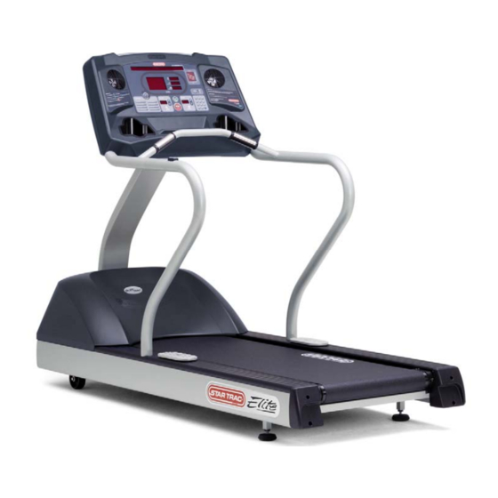
- Page 1 SERVICE MANUAL Pro Tread AC 7600 • 7700 Star Trac Fitness • 14410 Myford Road • Irvine, California 92606 • 800-503-1221 Tel • 714-669-1660 Tel • 714-669-0739 Fax http://support.startrac.com • email: support@startrac.com...
-
Page 2: Introduction
Service Manual: E-TR and E-TRi INTRODUCTION This is the Service Manual for the Star Trac AC Pro Tread 7600 & 7700. This manual is designed to be easy to use, providing detailed instructions on how to service and maintain the AC treadmills. Star Trac highly recommends that you read the entire manual prior to performing any maintenance or repair. -
Page 3: Table Of Contents
TABLE OF CONTENTS INTRODUCTION..............................1 TABLE OF CONTENTS ............................1 PRECAUTIONS - SAFETY ..........................4 ELECTRICAL SAFETY ..............................4 MECHANICAL SAFETY ............................... 4 EQUIPMENT PLACING ............................5 POWER (ELECTRICITY) ............................ 6 Objectives ..................................6 Safety ........................... Error! Bookmark not defined. Terminology ........................ - Page 4 Running Belt “Do Not’s” ................................15 Cleaning a Running Belt ..............................16 Running Belt Tension ..............................17 Running Belt Alignment ..............................20 Roller Care & Maintenance............................21 Applying Wax to a Waxless Running Belt ........................22 MAINTENANCE MODE ............................ 24 Engaging Maintenance Mode ............................24 Maintenance Mode Keys..............................
- Page 5 DFR Code 1000....................................59 DFR Code 800 & 400..................................60 DFR Code 200....................................61 DFR Code 40, 20 & 10...................................62 DFR Remaining Codes...................................63 Slipping Running Belt..................................64 Service Manual: E-TR and E-TRi...
-
Page 6: Precautions - Safety
PRECAUTIONS - SAFETY The 7600 and 7700 treadmills are wired for either 120 VAC nominal or 230 VAC nominal power input. They are equipped with a specific electric cord and plug to permit connection to the proper electric circuit. Make sure that the product is connected to a dedicated power line having an outlet with the same configuration as that of the plug. -
Page 7: Equipment Placing
EQUIPMENT PLACING Star Trac recommends that treadmills be spaced a minimum of 20.0 inches (0.5 m) apart to allow safe and easy ingress and egress. More importantly, there must be at least 48 inches (1.25 m) of free space behind the treadmill. The Pro Series treadmill measures: 85.5”... -
Page 8: Power (Electricity)
POWER (ELECTRICITY) Objectives If you are not qualified/comfortable working with electricity you should consult a certified electrician. This section should provide you with the information necessary to properly service your Star Trac unit by giving you: • A basic understanding of electrical safety •... -
Page 9: General Electricity
General Electricity Star Trac refers to the two most common global voltages as: • 110V (or 110VAC) • 220V (or 220VAC) Voltages worldwide can vary. Star Trac products are designed to be stable within most voltages: • For 110V systems the voltage range is: 110 VAC – 125 VAC 50/60hz •... -
Page 10: Power Cords
Power Cords Below are the power cords you will find installed onto a Star Trac treadmill. Note the configuration of the prongs for power and polarization: Service Manual: E-TR and E-TRi... -
Page 11: Preventive Maintenance
PREVENTIVE MAINTENANCE Overview Preventive maintenance (PM) is a schedule of planned maintenance actions aimed at the prevention of failures. PM is the best way to preserve and enhance equipment reliability by keeping key components clean and free of debris. PM activities may include cleaning, vacuuming, visual inspections of key components, lubrication, etc. -
Page 12: Preventive Maintenance Schedule
Preventive Maintenance Schedule This section provides a comprehensive list of factory recommended PM requirements, along with detailed procedures for performing each task. Wipe down all surfaces including: Display, handrails shroud and heart rate grips. Clean under the running belt (soft cloth only) Visually inspect running belt for alignment and tension Ensure the power cord is not under the treadmill Vacuum floor under and around treadmill... -
Page 13: Daily
DAILY Clean • Use a 5:1 dilution ratio (5 parts water to1 part Simple Green, Formula 409, Fantastic,or the like). (5 parts water) (1 part cleaner) Apply cleaning solution to a clean cloth then wipe the following areas (Do not spray directly onto surfaces): o Display (Keypad) o Heart Rate Grips... -
Page 14: Weekly
WEEKLY Clean Elevate the treadmill and vacuum the floor around and underneath. Inspect • Inspect display panel (keypad) for wear • Inspect inside of running belt and top of deck • Inspect all mounting hardware and correct any squeaks or rattles Service Manual: E-TR and E-TRi... -
Page 15: Monthly
MONTHLY Clean • Unplug the treadmill and remove the shroud. Use a portable vacuum with dust attachment to clean any dust, dirt or debris from inside the shroud area. Use extreme caution to not damage any components or knock and connections loose Inspect •... -
Page 16: Running Belt
RUNNING BELT Once a deck surface has been used, it should not be used again. You must install a new belt and new deck surface together. Most Star Trac decks are double-sided so they can be flipped to utilize both sides. Failure to install a new belt over a fresh deck surface will cause the belt to burn along the center walking area, the edges will curl, electrical components will create so much heat as to begin to fail, and will not be covered under warranty. -
Page 17: Importance Of Running Belt Maintenance
Importance of Running Belt Maintenance The running belt is the most important part of a treadmill. It is what a treadmill is all about. It is the core component that must be maintained to insure many years of continued function. By performing a few maintenance steps at regular intervals, you can help to: •... -
Page 18: Cleaning A Running Belt
Cleaning a Running Belt The running belt should be cleaned to help prevent dirt build up and maintain a nice appearance for users. To properly clean a running belt you will need: TOOLS & MATERIALS • Clean towel (1) • Paint stick or ruler (1) •... -
Page 19: Running Belt Tension
Running Belt Tension Proper running belt tension and tracking are important to maintain the performance and life of the belt. It is recommended to follow this tensioning and tracking procedure whenever the running belt or deck is replaced or as needed. PARTS REQUIRED •... - Page 20 RUNNING BELT RETENSION PROCEDURE Step 1: Release tension of running belt by unscrewing the tension screws until the roller touches the finger-guard. The belt should be completely relaxed. (Note: This applies to both left & right finger- guards.) Fig 1 Step 2: Apply a piece of masking tape on the edge of the running belt on both sides.
- Page 21 Step 4: Check to make sure that both lines are aligned with the edge of the deck at the same point. (See Fig 4) Fig 4 Step 5: Using a ruler or tape measure, draw a line on each piece of tape parallel to each first line at a distance of 3/8”...
-
Page 22: Running Belt Alignment
Running Belt Alignment Step 1: Start the treadmill and set the speed to 3.0 mph (5.0 kmh). Make sure the running belt tracks to the center (see Fig 7). If the running belt shifts or tracks to either side (left or right), follow the appropriate procedure below. -
Page 23: Roller Care & Maintenance
Roller Care & Maintenance The care and maintenance of the head and tail rollers are as important as the care and maintenance of the running belt. Dirt buildup on the rollers can cause noise, rough feelings and unwanted belt tracking. CLEANING Scrape any dirt and debris build up from the roller using a plastic scraper or an old credit card. -
Page 24: Applying Wax To A Waxless Running Belt
Applying Wax to a Waxless Running Belt While it is generally not necessary to add wax to a waxless style running belt, if the running belt is making unacceptable noises or is experiencing tracking difficulties, adding wax the underside of the belt will improve the grip between the belt and the rollers which will reduce the noise and improve the tracking response. - Page 25 Step 2: • Using the screwdriver, remove the three screws from the left and the three screws from the right finger guards (Fig 4). • Remove both finger guards (Fig 5). Fig 4 Fig 5 CAUTION: The next step involves working near moving parts. BE CAREFUL! Be mindful of loose clothing, long hair, loose and/or hanging jewelry, etc.
-
Page 26: Maintenance Mode
MAINTENANCE MODE The Maintenance Mode allows you to query and modify the settings of the Star Trac product. Engaging Maintenance Mode Press and hold the keys. While holding all three keys release the key only. A beep will sound and the display will read “MAINTENANCE MODE”... -
Page 27: Maintenance Mode Keys
Maintenance Mode Keys The following keys are used to search through and modify the Maintenance Settings: INCLINE keys: Display the next and previous parameters. SPEED keys: Adjust the value of the displayed parameter up and down respectively. Some parameters can utilize the number pad. ALPINE PASS: Sets parameter back to its default factory setting. -
Page 28: Display Parameters
DISPLAY PARAMETERS Parameter Defaults The following parameters can be accessed by entering the Maintenance Mode. When installing a new display electronic board, it will come with factory default settings. Depending on the model and voltage of unit you are installing the board into, you may need to adjust your settings by referencing the following chart. - Page 29 Parameter 110V Setting 220V Setting Default Parameter Ranges NO RAIL STOP 0 – 65535 KEY DOWN 0 – 65535 SPEED CHG 0 – 65535 ELEV STALL 0 – 65535 ELEV RANGE 0 – 65535 ELEV LOST 0 – 65535 CHECK MOTOR SYS 0 –...
-
Page 30: Parameter Setting Definitions
Parameter Setting Definitions The following are the definitions of each parameter from the Maintenance Mode. UNITS: Sets the conversion for speed, distance and weight between US and Metric measurements. (Conversions: Km = Miles x 1.6 • Lb = Kg x 2.2) MINIMUM SPEED: Sets the minimum start up speed for the unit. - Page 31 RAIL STOP: Used to turn the side stop switch port on or off on International units. *Note: This parameter should always be ON unless the mechanical stop switch is installed. STOP SWITCH: Sets the type of International stop switch is in use: U.S.A. or International 10_REV: Sets the speed and distance calculation value.
- Page 32 ELEVATION ZERO: Sets the value for 0% (zero percent) for the elevation motor sensor. ELEVATION MAX: Sets the value for 15% (maximum incline) for the elevation motor sensor. LAST DECK: This parameter is used for models with a waxable style running belt. If you have a waxless style treadmill and REWAX BELT appears on your display, go to the MODEL parameter and make sure your unit is set for the correct model.
-
Page 33: Maintenance Mode - Test Modes
MAINTENANCE MODE – TEST MODES Within the Maintenance Mode parameters are a few Test Modes that can be used to test various functions of the unit. While in the Maintenance Mode, set the following parameter and use the functions as listed to utilize each parameter. DISPLAY TEST The Display Test can be used to test each individual key for function and response, and can also be used to verify led function and display. -
Page 34: Calibrate Scale
CALIBRATE SCALE ⇒ Press ‘Start’ key Display will enter CALIBRATE SCALE mode and scroll the following: 1 = INPUT SPAN WEIGHT 2 = CAL SPAN WEIGHT Loop 3 = CAL ZERO WEIGHT 4 = VERIFY WEIGHT PRESS STOP TO EXIT ⇒... -
Page 35: Csafe Test
CSAFE TEST This parameter is used by Star Trac at the factory. HEART RATE TEST The Heart Rate Test mode can be used to simultaneously test the function and response for both the contact and Polar heart rate systems. ⇒ Press ‘Start’ key Display will read POLAR 0 CONTACT 0 CONTACT X should detect your heart rate then display the reading Grab the HR grips... -
Page 36: Maintenance Mode - Auto Calibration
MAINTENANCE MODE – AUTO CALIBRATION Electrical voltages vary between locations. The treadmill can run through an auto-calibration process to allow the electronics to balance out with the speed control. To run an auto-calibration procedure, do the following: Auto-Calibration DO NOT LEAVE THE TREADMILL UNATTENDED WHILE RUNNING THE AUTO-CALIBRATION PROCEDURE AS IT WILL RUN THE BELT TO THE MAXIMUM SPEED SETTING. -
Page 37: Last Error List Definitions
LAST ERROR LIST DEFINITIONS DEFINITIONS LAST CODE The last code (Check Speed Sys, Key Down, Elev Stall, etc.) LST CHK Check Sum at time of incident. Check Sum is part of the software language. LAST MTR CURR Motor Current sensed at time of incident. LAST STAT LAST OPHR Total unit OPER HOURS (Operating Hours) at time of incident. -
Page 38: Dfr Information
DFR INFORMATION DFR’s (Drive Fault Records) The AC MCB (Motor Control Board) monitors the drive system and reports any anomalies by triggering what is called a DFR (Drive Fault Record) code. Same Codes, Different Meanings The AC System has the same codes as the DC system but the meanings may not necessarily be the same, specifically “CHECK SPEED SYSTEM”... -
Page 39: Software - Display
SOFTWARE - DISPLAY The display on the AC Pro Tread contains the software to operate the treadmill. This software may be updated via the “uploaders” or by replacing the display electronics which contains an updated version of the software. Uploaders Uploaders are two small grey boxes that contain the primary (MC1) and secondary (MC2) software for the display. -
Page 40: Uploading Software Into The Uploaders
Uploading Software into the Uploaders The following procedure explains how to upload software into the grey uploader boxes. The software may be downloaded from the Star Trac Support Website (http://support.startrac.com/Software). Click on the Service Provider tab at the top then click on the Latest Product Software link. The Pro Tread Series display uses a flash memory system to store the software that runs the treadmill. - Page 41 You will need Winzip (or equivalent) installed on your PC. If you do not have a zip file extractor program, you can get a free version from www.winzip.com. Obtaining the FISP and Latest Software 4. Move your mouse pointer into the white space but do not hover over a folder.
- Page 42 7. Open your web browser in the Latest Extracting (Unzipping) the Zip Files Product Software section. Click on the latest Display Version of software for the 7000 (7k) 1. Open the ‘AVRISP’ folder. Right click on treadmills. ‘fisp_setup.zip’ then left click on ‘Open with Winzip’.
- Page 43 5. In the ‘AVRISP’ folder, right click on Connecting the USB Cable to the PC ‘Pro_tread-disp_verXX_XX.zip’ then left click on ‘Open with Winzip’. 1. On the back of your PC (or on the front on newer PC’s), locate the USB port. Plug the USB cable in to the USB port on the PC.
- Page 44 Installing the FISP Program on the PC 4. Create the Start Menu folder as ‘Fisp’. 1. In the ‘AVRISP’ folder, open the executable file for the FISP program called ‘fisp_setup.exe’. 5. This is your choice for a desktop icon. If a ‘Security Warning’ window appears, click ‘Run’).
- Page 45 Uploading the Software into the Uploader 5. Under the ‘Device’ drop down menu, choose the ‘Mega128’. 1. Be sure the upload is plugged in to the USB cable and the USB cable is plugged in to the PC and the Orange led is lit on the uploader. 2.
- Page 46 8. The ‘Device’ – ‘Options’ window will appear 10. Click on ‘Load Fisp’ to send software to the with several tabs. uploader. LOCK BITS - Uncheck all: 11. You will see a Transferring Date” status FUSE BITS – Check “SUT0 Fuse” only window.
-
Page 47: Software - Mcb
SOFTWARE - MCB Service Manual: E-TR and E-TRi... -
Page 48: Uploading Software Into The Ac Mcb With Mcb Uploader
Uploading Software into the AC MCB with MCB Uploader The following procedure explains how to upload software into the MCB (Motor Control Board) of the AC Pro Treadmill. The software may be downloaded from the Star Trac Support Website http://support.startrac.com. Click on the Service Provider tab at the top then click on the Latest Product Software link. - Page 49 6. Unplug JP1 and move it up one pin so it is now connected to the top two pins and the bottom pin is exposed (see Fig 3). 7. Unplug JP2 and move it down one pin so it is now connected to the bottom two pins and the top pin is exposed (see Fig 3).
- Page 50 Uploading to the MCB 1. Turn the treadmill on at the on/off switch. 2. Turn the treadmill power on. After 2 to 3 seconds the RED led on the uploader should light steady (see Fig 6) Fig 6 3. Press the RED button once. The Led’s should blink on and off then one led will remain lit.
- Page 51 7. Turn the power on at the on/off switch. 8. The LED’s near the jumpers J1 and J2 should be blinking. If they are lit solid: • Turn the power off and verify that the jumpers in the RUN mode positions. (NOTE: Do not move the jumpers with the power on.) If they are blinking, proceed to the next step.
-
Page 52: Part Replacement Procedures
PART REPLACEMENT PROCEDURES Table Of Part Replacement Procedures • Running Belt Tensioning Procedure • Display Panel (Keypad)/Electronics Replacement Service Manual: E-TR and E-TRi... -
Page 53: Running Belt Tensioning Procedure
Running Belt Tensioning Procedure Applies to models: 4500, 4000, 3900, 4200, 5500, 5600, 6500, 6600, 7500, 7600 and 7700 Proper running belt tension and tracking are important to maintain the performance and life of the belt. Star Trac recommends following this tensioning and tracking procedure whenever the running belt or deck are replaced or as needed. - Page 54 Step 2 Apply a piece of masking tape on the edge of the running belt on both sides. Fig 2 Step 3 Draw a line on each piece of masking tape aligned with the edge of the deck. (Note: Be careful not to move the belt or roller while drawing the lines.) Fig 3...
- Page 55 Step 4 Using a ruler or tape measure, draw a line on each piece of tape parallel to each first line at a distance of 3/8” (9.5mm) from each first line. (See Fig 5) Step 5 You are now ready to begin tensioning the belt. Before beginning, make sure the line on each Fig 5 piece of tape closest to the tail roller is aligned...
- Page 56 Step 1 Start the treadmill and set the speed to 3.0 mph (5.0 kph). Make sure the running belt tracks to the center (see Fig 7). If the running belt shifts or tracks to either side (left or right), follow the appropriate procedure below.
-
Page 57: Troubleshooting
TROUBLESHOOTING Table Of Troubleshooting Documents • Check Speed System and Check Motor System • Troubleshoot DFR Codes: • Code: 1000000, 100000, 10000 • Code: 4000 • Code: 1000 • Code: 800 & 400 • Code: 200 • Code: 40, 20 & 10 •... -
Page 58: Check Speed System" And "Check Motor System
“Check Speed System” and “Check Motor System” Flowchart for Display Codes: “CHECK SPEED SYSTEM” & “CHECK MOTOR SYSTEM” Start Press # 4 key Press # 2 key Press 0, 2, and start keys simultaneously Does the Does the Last Code (4) read Last Code (2) read Check MO or Check MO or... -
Page 59: Dfr Code 1000000, 100000 And 10000
DFR Code 1000000, 100000 and 10000 Service Manual: E-TR and E-TRi... -
Page 60: Dfr Code 4000
DFR Code 4000 Service Manual – Treadmills: E-Series • P-Series... -
Page 61: Dfr Code 1000
DFR Code 1000 Service Manual – Treadmills: E-Series • P-Series... -
Page 62: Dfr Code 800 & 400
DFR Code 800 & 400 DFR CODE FLOWCHART: DEFINITIONS / MCB LED Blinks DFR Flowchart For #: 800 & 400 DFR Code = 800 DFR Code = 400 Phase Over Current / 12 Blinks Illegal Speed Command / 11 Blinks Possible Causes: Possible Causes: (1) Worn running belt. -
Page 63: Dfr Code 200
DFR Code 200 DFR CODE FLOWCHART: DEFINITIONS / MCB LED Blinks DFR Flowchart For #: 200 DFR Code = 200 DC Link Bus Under Voltage / 10 Blinks Possible Causes: (1) Low AC voltage from wall. (2) Low AC voltage from EMI filter. (3) Faulty MCB. -
Page 64: Dfr Code 40, 20 & 10
DFR Code 40, 20 & 10 DFR CODE FLOWCHART: DEFINITIONS / MCB LED Blinks DFR Flowchart For #: 40, 20 & 10 DFR Code = 40 Phase A Circuit Open / 7 Blinks DFR Code = 20 Phase B Circuit Open / 6 Blinks DFR Code = 10 Solution: Phase C Circuit Open / 5 Blinks... -
Page 65: Dfr Remaining Codes
DFR Remaining Codes Service Manual – Treadmills: E-Series • P-Series... -
Page 66: Slipping Running Belt
Slipping Running Belt Slipping is the term that many people use when a running belt stops moving for a split second, but the motor, possibly the head roller, keeps moving. Possible causes for a slipping running belt: • Loose drive belt •... - Page 67 This page intentionally left blank Service Manual - AC Pro Tread 7600 • 7700...
- Page 68 SERVICE MANUAL Star Trac Fitness • 14410 Myford Road • Irvine, California 92606 • 800-503-1221 Tel • 714-669-1660 Tel • 714-669-0739 Fax http://support.startrac.com • email: support@startrac.com Rev: B Doc: 620-7734...
Need help?
Do you have a question about the Pro Tread AC 7600 and is the answer not in the manual?
Questions and answers