Raymarine p70 Installation & Operation Instructions
Autopilot control head/pilot controllers
Hide thumbs
Also See for p70:
- Installation and operation instructions manual (104 pages) ,
- Operation instructions manual (84 pages) ,
- Installation instructions manual (80 pages)

Related Manuals for Raymarine p70


Summary of Contents for Raymarine p70
- Page 1 Pilot Controller INSTALLATION & OPERATION INSTRUCTIONS English (EN) Date: 05-2016 Document number: 81355-2 © 2016 Raymarine UK Limited...
- Page 3 Software updates Important: Check the Raymarine website for the latest software releases for your product. www.raymarine.com/software Product handbooks The latest versions of all English and translated handbooks are available to download in PDF format from the website www.raymarine.com.
-
Page 5: Table Of Contents
Contents Chapter 1 Important information......7 7.4 Initial setup and commissioning......41 7.5 Powering the Pilot controller on......42 TFT Displays ............... 8 7.6 Using the Set-up Wizard........43 Water ingress .............. 8 7.7 Using the Dockside wizard........43 Disclaimer ..............8 7.8 Adjusting the hard-over time —... - Page 6 14.5 Performing a Factory Reset ......104 Chapter 15 Technical specification....105 15.1 Technical specification ........106 Chapter 16 Technical support ......107 16.1 Raymarine product support and servicing... 108 16.2 Learning resources........... 109 Chapter 17 Spares and accessories ....111 17.1 Spares and accessories........112 17.2 SeaTalk...
-
Page 7: Chapter 1 Important Information
Authorized Raymarine Service has positive grounding. Representative fits this product. You will only receive full warranty benefits if you can show that an Authorized Raymarine Warning: Switch off power supply Service Representative has installed and Ensure the vessel’s power supply is commissioned this product. -
Page 8: Tft Displays
Suppression ferrites washing. Raymarine will not warrant products subjected to high-pressure washing. • Raymarine cables may be pre-fitted or supplied with suppression ferrites. These are important for correct EMC performance. If ferrites are supplied Disclaimer separately to the cables (i.e. -
Page 9: Warranty Registration
To the best of our knowledge, the information in this document was correct at the time it was produced. However, Raymarine cannot accept liability for any inaccuracies or omissions it may contain. In addition, our policy of continuous product improvement may change specifications without notice. - Page 10 / p70R...
-
Page 11: Chapter 2 Document And Product Information
Chapter 2: Document and product information Chapter contents • 2.1 Document information on page 12 • 2.2 Product overview on page 13 Document and product information... -
Page 12: Document Information
Your product may differ slightly from that shown This document contains important information in the illustrations in this document, depending on related to the installation of your Raymarine product. product variant and date of manufacture. The document includes information to help you: All images are provided for illustration purposes only. -
Page 13: Product Overview
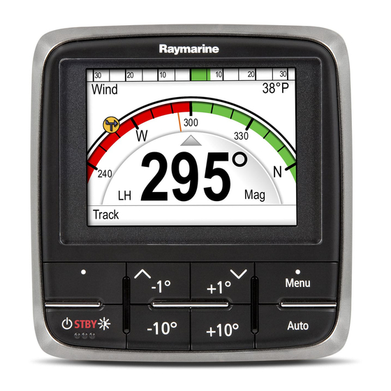
The p70 and p70R are SeaTalk autopilot controllers. STBY STBY D13016-1 1. p70 (8 button pilot control head) 2. p70R (Rotary pilot control head) The unit has the following features: • 2 x SeaTalk connections • Compatible with NMEA 2000 and SeaTalk standards. - Page 14 / p70R...
-
Page 15: Chapter 3 Planning The Installation
Chapter 3: Planning the installation Chapter contents • 3.1 Installation checklist on page 16 • 3.2 Pack contents on page 16 • 3.3 Compatible autopilot systems on page 17 • 3.4 Software updates on page 17 • 3.5 Tools on page 18 •... -
Page 16: Installation Checklist
• Location of all components. • Connectors, cable types, routes and lengths. D12098-1 Number Description p70 / p70R Pilot controller (p70 8 button controller is shown in diagram above.) Bezel Gasket Suncover 4 x fixing screws Document pack... -
Page 17: Compatible Autopilot Systems
3.3 Compatible autopilot systems 3.4 Software updates Your product is compatible with the Raymarine The software running on the product can be updated. Autopilot systems shown below. • Raymarine periodically releases software updates Product Description Connection to improve product performance and add new features. -
Page 18: Tools
Additional instruments and functions can be added to a SeaTalk system, simply by plugging them into the network. SeaTalk equipment can also communicate with other non-SeaTalk equipment via the NMEA 0183 standard, provided a suitable interface is used. p70 / p70R... -
Page 19: Warnings And Cautions
3.7 Warnings and cautions 3.8 General location requirements When selecting a location for your display it is Important: Before proceeding, ensure that you important to consider a number of factors. have read and understood the warnings and cautions provided in the Chapter 1 Important Key factors which can affect product performance information... -
Page 20: Unit Dimensions
(2ft 6in) 14 mm (0.55”) 30 mm (1.18”) 35 mm (1.38”) D12031-1 Site requirements for the p70 / p70r Pilot controller 90 mm (3.54”) are as follows: 17 mm (0.67”) • There should be no obstacle between the user 20.6 mm (0.81”) and the pilot controller. -
Page 21: Chapter 4 Cables And Connections
Chapter 4: Cables and connections Chapter contents • 4.1 General cabling guidance on page 22 • 4.2 Connections overview on page 22 • 4.3 SeaTalk power supply on page 23 ng® • 4.4 SeaTalk connection on page 25 • 4.5 SeaTalk connection on page 26 •... -
Page 22: General Cabling Guidance
Raymarine. NMEA 2000 SeaTalk • Ensure that any non-Raymarine cables are of the backbone DeviceNet correct quality and gauge. For example, longer adaptor power cable runs may require larger wire gauges... -
Page 23: Seatalk Ng® Power Supply
In the example above the system has an overall LEN please consult an authorized Raymarine dealer or of 10, so the optimum connection point would be to a suitably qualified professional marine electrician. - Page 24 (12 V dc) is available at the SeaTalk backbone’s power connection. ng® More information Raymarine recommends that best practice is observed in all vessel electrical installations, as detailed in the following standards: • BMEA Code of Practice for Electrical and Electronic Installations in Boats •...
-
Page 25: Seatalk Ng Connection
Description ACU unit SPX (supplying 12V to SeaTalk network.) 2 x Instruments 2 x Instruments p70 / p70R Pilot controller p70 / p70R Pilot controller Vessel’s 12 V dc power supply Vessel’s 12 V dc power supply EV unit SeaTalk 5–way connectors with terminators... -
Page 26: Seatalk Connection
Depth transducer Speed transducer Course computer (supplying 12V to SeaTalk network.) For SeaTalk cables and extensions, use Raymarine SeaTalk cable accessories. SeaTalk power protection The power supply must be protected by a 5 A fuse or a circuit breaker providing equivalent protection. -
Page 27: Nmea 2000 Network Connection
4.6 NMEA 2000 network connection Your SeaTalk device can be connected to a ng® DeviceNet / NMEA 2000 network. SeaTalk device NMEA 2000 D12060-3 1. SeaTalk device ng® 2. SeaTalk to DeviceNet adaptor cable ng® (A06045) 3. DeviceNet T-piece 4. NMEA 2000 backbone Cables and connections... - Page 28 / p70R...
-
Page 29: Chapter 5 Installation
Chapter 5: Installation Chapter contents • 5.1 Mounting on page 30 Installation... -
Page 30: Mounting
5. Ensure that the unit fits into the removed area and then file around the cut edge until smooth. 6. Drill four holes as indicated on the template to accept the securing screws. p70 / p70R... -
Page 31: Chapter 6 Getting Started
Chapter 6: Getting started Chapter contents • 6.1 Pilot controls on page 32 • 6.2 Before using your product on page 33 • 6.3 Powering the Pilot controller on on page 33 • 6.4 Completing the startup wizard on page 34 •... -
Page 32: Pilot Controls
6.1 Pilot controls p70r — rotary pilot controller Control layout and functions. p70 – 8 button pilot controller STBY D12109-2 STBY Item Description LEFT SOFT BUTTON Cancel, Back, mode selection. D12108-2 Item Description STANDBY BUTTON Disengage pilot, Manual control, Power, LEFT SOFT BUTTON Brightness. -
Page 33: Before Using Your Product
6.2 Before using your product 6.3 Powering the Pilot controller on 1. Press and hold the STANDBY button for one Commissioning second, until the logo appears. Before using your autopilot system for the first time If the unit is being switched on for the first time you must ensure that the system has been correctly or after a factory reset the set up wizard will be commissioned in accordance with the supplied... -
Page 34: Completing The Startup Wizard
3. Select Continue. The first of a pre-defined set of Favorite pages is displayed. Note: The Startup Wizard may not be displayed if these settings have already been set on the system that the unit is connected to. p70 / p70R... -
Page 35: Display Settings
6.6 Display settings Assigning A Network Group To enable the Shared Brightness and Color, unit’s Adjusting the unit’s brightness must be assigned to the same network group. To adjust the unit’s LCD brightness level, when it Compatible Instrument Displays and Pilot Controllers is not part of a Shared Brightness group follow the will also share their Color Scheme. -
Page 36: Multiple Data Sources (Mds) Overview
4. Select Save. that are NOT MDS-compliant. It may be possible to upgrade the software for these products, to make them compliant. Visit the Raymarine website (www.raymarine.com) to obtain the latest software for your products. If MDS-compliant software is not available for the... - Page 37 3. Select your preferred data source, or 4. Select Auto to allow the system to decide. ACTIVE is displayed next to the data source that is the current source for the data type. Getting started...
- Page 38 / p70R...
-
Page 39: Chapter 7 Commissioning - Evolution Autopilot System
Chapter 7: Commissioning - Evolution autopilot system Chapter contents • 7.1 Evolution autopilot installation on page 40 • 7.2 Autopilot commissioning — main differences between Evolution and SPX systems on page 40 • 7.3 Autopilot response levels on page 41 •... -
Page 40: Evolution Autopilot Installation
• Automatic set-up — the rudder gain, counter rudder, manual compass calibration and autolearn settings required for existing SPX systems are no longer required. This results in a greatly simplified dockside calibration process for Evolution autopilot systems. p70 / p70R... -
Page 41: Autopilot Response Levels
Initial set-up involves the following steps: Important: Before proceeding with the initial set-up or commissioning of an Evolution autopilot system with a p70, p70s, p70R or p70Rs Pilot Controller, ensure that the Pilot controller, EV and ACU software is updated to the latest versions. -
Page 42: Powering The Pilot Controller On
STANDBY button. After 1 second a pop up count down is displayed. 3. Continue to hold the STANDBY button for a further 3 seconds to complete the power off. Note: You cannot power off the Pilot controller whilst the Autopilot is engaged. p70 / p70R... -
Page 43: Using The Set-Up Wizard
Note: If your drive type is not listed, contact your and drive type. Therefore, the available vessel hull Raymarine dealer for advice. type options are provided for guidance only. You may wish to experiment with the different vessel hull... - Page 44 2. Disengage any rudder drive clutch. 3. Select CONTINUE. 4. Check it is safe to proceed before selecting OK. For vessels with a rudder reference transducer, the autopilot will now automatically move the rudder to port and then starboard. p70 / p70R...
-
Page 45: Adjusting The Hard-Over Time - Smartpilot And Spx
3. Engage Auto mode. 4. Press the +10 and +1 buttons at the same time (p70/p70s) or use the Rotary (p70R/p70Rs) to alter your locked heading by 90 degrees, use a stop watch to time the movement of the rudder / engine. - Page 46 EV unit is moved 2. Select Compass Offset. and re-installed in a location which is subject to 3. Use the +/- 10 button (p70/p70s) or ROTARY less magnetic interference. After the linearization control (p70R/p70Rs) to adjust the compass process has successfully completed you can check offset as appropriate.
-
Page 47: Compass Lock
7.10 Compass lock Once you are satisfied with the compass accuracy, you can lock the setting to prevent the autopilot system from completing a further automatic linearization in the future. This feature is particularly useful for vessels in environments that are exposed to strong magnetic disturbances on a regular basis (such as offshore wind farms or very busy rivers, for example). - Page 48 / p70R...
-
Page 49: Chapter 8 Commissioning - Spx And Smartpilot Systems
Chapter 8: Commissioning - SPX and SmartPilot systems Chapter contents • 8.1 SPX and SmartPilot autopilot installation on page 50 • 8.2 Pilot response on page 50 • 8.3 Initial setup and commissioning on page 51 • 8.4 Powering the Pilot controller on on page 51 •... -
Page 50: Spx And Smartpilot Autopilot Installation
Levels 7 to 9 Gives the tightest course keeping and greatest rudder activity (and power consumption). This can lead to a rough passage in open waters as the SPX system may ‘fight’ the sea. p70 / p70R... -
Page 51: Initial Setup And Commissioning
8.3 Initial setup and commissioning 8.4 Powering the Pilot controller on 1. Press and hold the STANDBY button for one Commissioning pre-requisites second, until the logo appears. Before commissioning your system for the first time, If the unit is being switched on for the first time check that the following processes have been carried or after a factory reset the set up wizard will be out correctly:... -
Page 52: Using The Set-Up Wizard
When choosing a suitable vessel type, the emphasis should be on safe and dependable steering response. p70 / p70R... -
Page 53: Dockside Calibration
7. You will be asked to confirm the rudder turned to Note: If your drive type is not listed, contact your starboard by selecting YES or NO. Raymarine dealer for advice. 8. Dockside calibration is now complete, select CONTINUE. Checking the rudder alignment (Align Note: If you confirmed a “NO”... -
Page 54: Dealer Settings
The dealer settings menu can be accessed from: Main menu > Set up > Auto pilot calibration > Dealer settings. Once entered the dealer settings menu will cycle through all available options. Options and limits are dependent on the course computer installed. p70 / p70R... -
Page 55: Adjusting The Hard-Over Time - Smartpilot And Spx
Note: The Sea trial wizard can be cancelled at any 4. Press the +10 and +1 buttons at the same time time by pressing the Standby button. (p70/p70s) or use the Rotary (p70R/p70Rs) to alter your locked heading by 90 degrees, use a Warning: Seatrial calibration... - Page 56 Performing Auto learn Auto learn is available from the Sea trial wizard, or from the Commissioning menu. Maintain a normal cruising speed (at least 3 kts) throughout the auto learn process. p70 / p70R...
-
Page 57: Checking Autopilot Operation
8.10 Checking autopilot operation Checking counter rudder Counter rudder is the amount of rudder your autopilot After completing calibration, check the basic autopilot applies to try to prevent your vessel from over operation, as follows: steering. A higher counter rudder setting results in 1. - Page 58 / p70R...
-
Page 59: Chapter 9 Pilot Modes
Chapter 9: Pilot modes Chapter contents • 9.1 Auto on page 60 • 9.2 Mode menu on page 61 • 9.3 Patterns on page 61 • 9.4 Track mode on page 62 • 9.5 Wind vane mode (Sailing boats only) on page 64 •... -
Page 60: Auto
2. Use the +1 and +10 buttons, or turn the rotary controller clockwise to change the vessel's course to starboard. Pressing +1 button will increment the course to starboard by 1º and +10 will increment by 10º. p70 / p70R... -
Page 61: Mode Menu
9.2 Mode menu 9.3 Patterns Pilot modes are accessed from the Mode menu. The Fishing patterns are available, that can be used available modes are determined by the autopilot with their default settings or adjusted to your own system and the selected Vessel Hull Type. preference. -
Page 62: Track Mode
The size of the waypoint arrival circle can be customized, if the arrival circle is changed so that the radius is 0.3 nm or greater from the waypoint this can result in a cross track error alarm. p70 / p70R... - Page 63 Waypoint arrival circle • you request waypoint advance by pressing Track for 1 second in track mode (with SeaTalk navigators only). • the boat arrives at the target and the navigator accepts the next waypoint. • you activate the Man Overboard (MOB) function. When the warning sounds, the autopilot continues on its current heading but displays: •...
-
Page 64: Wind Vane Mode (Sailing Boats Only)
For example, to bear away by 10° when the boat is on a starboard tack: i. press -10 to turn the boat 10° to port – the locked wind angle and locked heading will both change by 10°. p70 / p70R... - Page 65 If the autopilot detects a wind shift of more than 15° it will trigger the Wind Shift Alarm. In Wind Vane mode: 1. Using a p70 / p70s: Enabling and disabling the Wind Shift alarm i. Press the -1 and -10 buttons at the same time The Wind Shift alarm is turned on by default, you can to Tack to port.
-
Page 66: Power Steer
Note: In order to use Bang Bang mode a the Sail Boat Settings menu: Menu > Set-up > connected joystick is required, the p70Rs rotary Autopilot Calibration > Sail Boat Settings > will only perform in Proportional mode. Gybe Inhibit . p70 / p70R... -
Page 67: Jog Steer (Tiller Pilots Only)
9.7 Jog steer (tiller pilots only) 9.8 Shortcut key If you have a tiller drive installed on a SeaTalk When in pilot view you can assign pilot modes to network, your vessel you can use the pilot controller the LEFT SOFT button as a shortcut depending on to operate the ram in Jog steer mode. - Page 68 / p70R...
-
Page 69: Chapter 10 Pilot Views
Chapter 10: Pilot views Chapter contents • 10.1 Available pilot views on page 70 • 10.2 Graphical view on page 70 • 10.3 Large view on page 71 • 10.4 Standard view on page 71 • 10.5 Multiple view on page 72 •... -
Page 70: Available Pilot Views
Waypoint 7 DTW: 6 nm TTG: 1h02m LH: 051 XTE: 0.13nm Track D13025-1 DTW — Distance To Waypoint Destination waypoint TTG — Time To Go Destination waypoint name Locked Heading XTE — Cross Track Error Vessel position p70 / p70R... -
Page 71: Large View
10.3 Large view 10.4 Standard view The Large view has been optimized to provide the The Standard view provides large sized heading largest possible sized text for heading data. data combined with data boxes which provide further information. Auto Hdg 304 Pattern TWS(Kts) Depth(ft) -
Page 72: Multiple View
Shortcut key — Left Soft button • Track (default) • Track (default) • Pattern • Pattern • Wind Vane • Wind Vane Track line • Current heading — Standby and Power Steer • Locked heading — Auto, Wind Vane, Track and Pattern p70 / p70R... -
Page 73: View
10.7 Setting the pilot view 10.8 Setting up data boxes To set the pilot view to your desired layout: The Standard, Multiple and 2D Pilot views include data boxes which you can customize to display 1. Go to the Pilot view menu: Main menu > Pilot different data. - Page 74 / p70R...
-
Page 75: Chapter 11 Pilot Controller Alarms
Chapter 11: Pilot controller alarms Chapter contents • 11.1 Alarms on page 76 Pilot controller alarms... -
Page 76: Alarms
Calibration Indicates a Dockside required pilot that has and Seatrial not been fully calibration calibrated. needs to be Initiated in undertaken. Standby • Change mode, for a pilot mode few seconds after initial • Self power-up. cancelling p70 / p70R... - Page 77 Alarm name Alarm type Description Action Alarm name Alarm type Description Action Auto release Safety Alarm Appears • Pilot drops SeaTalk fail Safety Alarm Total • Check when the to standby SeaTalk data connec- user has and alarm transmission tions for taken back times out problem.
- Page 78 & Wind drive error. modes. AutoLearn Safety Alarm AutoLearn • Restart • XTE – fail 5 has failed Track due to motor toLearn. mode. going into current limit. • Wind angle – Wind vane mode. p70 / p70R...
- Page 79 Alarm name Alarm type Description Action Alarm name Alarm type Description Action Pilot start up Alarm Will display • Self Clutch short Warning Indicates a • Check start up for cancelling. short circuit clutch con- 20 seconds in the Clutch nections at everytime SPX and...
- Page 80 / p70R...
-
Page 81: Chapter 12 Set Up Menu Options
Chapter 12: Set up menu options Chapter contents • 12.1 Set up menu on page 82 • 12.2 Autopilot calibration menu on page 82 • 12.3 User preferences menu on page 90 • 12.4 System set-up menu on page 92 •... -
Page 82: Set Up Menu
Diagnostics Information About • Yes the display and • No system and key beep on / off setting. Set-up Wizard Launch the initial • Language set-up wizard. • Vessel hull type • Welcome page p70 / p70R... - Page 83 Menu Options Sail Boat Settings • Gybe Inhibit • Wind Type • Wind Trim Response • Wind Shift Alarm Commissioning • Dockside Wizard • Sea Trial Wizard • Motor Phasing • Swing Compass • Auto Learn • Align Compass GPS •...
-
Page 84: Vessel Settings
• Rotary Drive Type 1 — ACU-200 • Constant running pump. and ACU-400 • Verado • Rotary Drive Type 2 — ACU-400 only • Hydraulic Pump Type 1 (0.5L) — ACU-100 only • Hydraulic Pump Type 1 — ACU-200 and ACU-400 p70 / p70R... - Page 85 SeaTalk and SPX SmartPilot Item Description Evolution autopilots Options • Hydraulic Pump Type 2 — ACU-400 only • Hydraulic Pump Type 3 — ACU-400 only • Verado — ACU-200 and ACU-400 • Auto Speed Input Select the source for speed data. In Auto the system will automatically •...
-
Page 86: Drive Settings
This setting defines the amount of course change when performing an • 10º — 125º auto turn. • 90º (default) Note: This option cannot be changed when connected over SeaTalk. Note: This option is only available on motor vessels. p70 / p70R... - Page 87 Item Description Options Response level This sets the default autopilot system response level setting. The Evolution response level controls the relationship between course keeping • Performance accuracy and the amount of helm / drive activity. You can make temporary changes to response during normal operation. •...
- Page 88 Wind Shift This option enables you to enable • On (default) Alarm and disable the Wind Shift alarm. • Off Note: These features are only available if wind data is available. p70 / p70R...
-
Page 89: User Settings
Commissioning menu Commissioning menu options are dependant on connected autopilot system. SeaTalk and SPX Menu option Description Evolution autopilots SmartPilots Dockside Wizard Initiates the Dockside wizard process. Sea Trial Wizard Initiates the Sea Trial wizard process. Motor phasing Initiates the motor phasing (drive check) wizard Initiates the swing compass Swing Compass... -
Page 90: User Preferences Menu
• LPH — Liters per hour. Heading: • Mag — magnetic. • True Pressure • PSI — pounds per square inch. • Bar — bar. • kPa — Kilo pascals. Volume: • UK Gallons • US Gallons p70 / p70R... - Page 91 Menu item Description Options • ltr — liter. Language Determines the language that will be used for all • English (UK) on-screen text, labels, menus and options. • English (US) • Chinese • Croatian • Danish • Dutch • Finnish •...
-
Page 92: System Set-Up Menu
Data source found • model name — serial number Port ID Data source details • Device name • Serial No. • Port ID • Status or No data About system set-up Provides information about the System set-up menu. p70 / p70R... -
Page 93: Diagnostics Menu
12.5 Diagnostics menu You can access diagnostics details from the Diagnostics menu: (Menu > Set-up > Diagnostics). Menu item Description Options About display Allows you to view information about the display • Software version you are using: • Hardware version •... - Page 94 / p70R...
-
Page 95: Chapter 13 Maintenance
Chapter 13: Maintenance Chapter contents • 13.1 Routine equipment checks on page 96 • 13.2 Product cleaning on page 96 • 13.3 Cleaning the display screen on page 97 • 13.4 Cleaning the display case on page 97 • 13.5 Cleaning the sun cover on page 98 Maintenance... -
Page 96: Routine Equipment Checks
13.1 Routine equipment checks 13.2 Product cleaning Raymarine strongly recommends that you complete Best cleaning practices. a number of routine checks to ensure the correct and When cleaning products: reliable operation of your equipment. • If your product includes a display screen, do NOT... -
Page 97: Cleaning The Display Screen
13.3 Cleaning the display screen 13.4 Cleaning the display case A coating is applied to the display screen. This The display unit is a sealed unit and does not require makes it water repellent, and prevents glare. To regular cleaning. If it is necessary to clean the unit, avoid damaging this coating, follow this procedure: follow this basic procedure: 1. -
Page 98: Cleaning The Sun Cover
1. Carefully remove the sun cover from the display. 2. Rinse the sun cover with fresh water to remove all dirt particles and salt deposits. 3. Allow the sun cover to dry naturally. p70 / p70R... -
Page 99: Chapter 14 System Checks And Troubleshooting
Chapter 14: System checks and troubleshooting Chapter contents • 14.1 Troubleshooting on page 100 • 14.2 Power up troubleshooting on page 101 • 14.3 System data troubleshooting on page 102 • 14.4 Miscellaneous troubleshooting on page 103 • 14.5 Performing a Factory Reset on page 104 System checks and troubleshooting... -
Page 100: Troubleshooting
All Raymarine products are, prior to packing and shipping, subjected to comprehensive test and quality assurance programs. However, if you experience problems with the operation of your... -
Page 101: Power Up Troubleshooting
Software corruption In the unlikely event that the products software has become corrupted please try re-flashing the latest software from the Raymarine website. On display products, as a last resort, you can try to perform a ‘Power on Reset’, however this will delete all settings/presets and user data (such as waypoints and tracks) and revert the unit back to factory defaults. -
Page 102: System Data Troubleshooting
Network problem. Check that all required equipment is connected to the is missing from some but not all network. displays. Check the status of the Raymarine network Switch. Check that SeaTalk / RayNet cables are free from damage. Software mismatch between Contact Raymarine technical support. -
Page 103: Miscellaneous Troubleshooting
Check that the power source is of the correct voltage and erratic behavior. sufficient current. Software mismatch on system Go to www.raymarine.com and click on support for the (upgrade required). latest software downloads. Corrupt data / other unknown Perform a factory reset. -
Page 104: Performing A Factory Reset
Note: Performing a factory reset will erase all saved data and customized settings. 1. Press the Menu button. 2. Select Set Up. 3. Select Factory Reset. 4. Select Yes. Your unit will now reset itself to factory default settings. p70 / p70R... -
Page 105: Chapter 15 Technical Specification
Chapter 15: Technical specification Chapter contents • 15.1 Technical specification on page 106 Technical specification... -
Page 106: Technical Specification
TFT LCD display, 16bit color (64k colors) Resolution: 320x240 Brightness: 700 cd/m Data connections 2 x SeaTalk ports (fulling compliant with NMEA2000 & SeaTalk specifications). Conformance • Europe 2004/108/EC • Australia and New Zealand C-Tick, compliance level 2 p70 / p70R... -
Page 107: Chapter 16 Technical Support
Chapter 16: Technical support Chapter contents • 16.1 Raymarine product support and servicing on page 108 • 16.2 Learning resources on page 109 Technical support... -
Page 108: Raymarine Product Support And Servicing
Servicing and warranty 3614 905 Raymarine offers dedicated service departments for Sweden support.se@raymarine.com warranty, service, and repairs. (0)317 (Raymarine subsidiary) Don’t forget to visit the Raymarine website to 633 670 register your product for extended warranty benefits: Finland +358 support.fi@raymarine.com http://www.raymarine.co.uk/display/?id=788. (0)207... -
Page 109: Learning Resources
Internet connection. • Some videos are only available in English. Training courses Raymarine regularly runs a range of in-depth training courses to help you make the most of your products. Visit the Training section of the Raymarine website for more information: •... - Page 110 / p70R...
-
Page 111: Chapter 17 Spares And Accessories
Chapter 17: Spares and accessories Chapter contents • 17.1 Spares and accessories on page 112 • 17.2 SeaTalk cables and accessories on page 112 ng® • 17.3 SeaTalk cable kits on page 114 • 17.4 SeaTalk accessories on page 117 Spares and accessories... -
Page 112: Spares And Accessories
Part number Description SeaTalk cables and accessories for use with R22168 Spare bezel compatible products. R22169 p70 Sun cover Description Part No Notes R22174 p70r Sun cover SeaTalk starter kit T70134 Includes: • 1 x 5 Way connector (A06064) •... - Page 113 Description Part No Notes SeaTalk to bare A06044 ends 3 m (9.8 ft) spur SeaTalk Power A06049 cable SeaTalk A06031 Terminator SeaTalk T-piece A06028 Provides 1 x spur connection A06064 Provides 3 x spur SeaTalk 5–way connections connector A06030 SeaTalk backbone extender SeaTalk to E22158...
-
Page 114: Seatalk Ng Cable Kits
SeaTalk Backbone kit (A25062) Quan- Parts included tity Connector A Cable Connector B Length Backbone cable 5 m (16.4 ft) ((A06036)) Backbone cable 20 m (65.6 ft) ((A06037)) Power cable 1 m (3.3 ft) (A06049) p70 / p70R... - Page 115 Quan- Parts included tity Connector A Cable Connector B Length T-piece (A06028) Backbone terminator (A06031) SeaTalk Evolution cable kit (R70160) Quan- Parts included tity Connector A Cable Connector B Length Backbone cable 5 m (16.4 ft) ((A06036)) Power cable 1 m (3.3 ft) (A06049) Spur cable 1 m (3.3 ft)
- Page 116 1 m (3.3 ft) (A06049) Backbone terminator (A06031) Blanking plug(A06032) SeaTalk (3 pin) 0.4 m (1.3 ft) adapter cable (A06047) SeaTalk to SeaTalk con- verter(E22158). Enables the con- nection of SeaTalk devices to a SeaTalk sys- tem. p70 / p70R...
-
Page 117: Seatalk Accessories
17.4 SeaTalk accessories SeaTalk cables and accessories for use with compatible products. Description Part No Notes D244 3–way SeaTalk junction box D284 1 m (3.28 ft) SeaTalk extension cable 3 m (9.8 ft) SeaTalk D285 extension cable 5 m (16.4 ft) D286 SeaTalk extension cable... - Page 118 / p70R...
-
Page 119: Appendix A Supported Nmea 2000 Pgn List
● 129044 Datum when Calibration ● Lock is enabled. 129283 Cross Track Error ● V2.12 81355–1 / p70 / p70R • Added Rudder 129284 Navigation Data 82285–5 bar indicator ● 129291 Set & Drift, Rapid to Dockside Update Calibration, ●... - Page 120 Software uct man- compati- version bility Changes V1.08 81355–1 p70 / p70R • Corrected unit reset when unit is set to Swedish • Improved compatibility on multiple control head systems V1.06 81331–1 p70 / p70R • Initial Release...
- Page 122 Raymarine UK Limited, Marine House, Cartwright Drive, Fareham, PO15 5RJ. United Kingdom. Tel: +44 (0)1329 246 700...
Need help?
Do you have a question about the p70 and is the answer not in the manual?
Questions and answers
P70 the bar on bottom changes to blue and red what are they