Table of Contents
Advertisement
Quick Links
Harbor Breeze
®
is a registered trademark
of LF, LLC. All Rights Reserved.
ATTACH YOUR RECEIPT HERE
Serial Number
Questions, problems, missing parts? Before returning to your retailer, call our customer
service department at 1-800-643-0067, 8 a.m. - 6 p.m., EST, Monday - Thursday,
8 a.m. - 5 p.m., EST, Friday.
EB14428
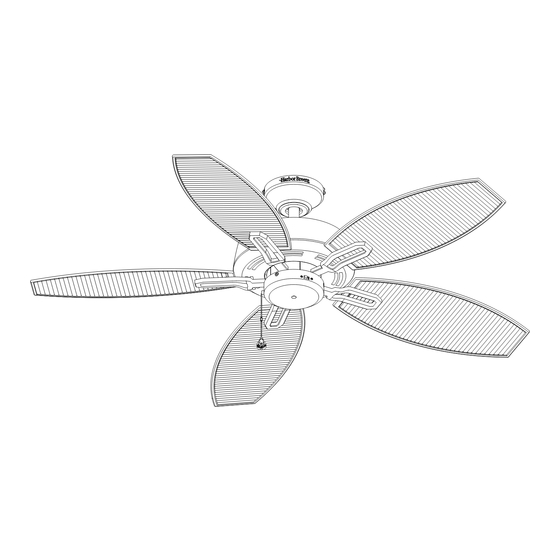
OCRACOKE CEILING FAN
Purchase Date
1
ITEM #0451812
MODEL #L1305
Español p. 19
Lowes.com/harborbreeze
Advertisement
Table of Contents

Related Manuals for Harbor Breeze L1305


Summary of Contents for Harbor Breeze L1305
- Page 1 ITEM #0451812 OCRACOKE CEILING FAN MODEL #L1305 Harbor Breeze ® is a registered trademark Español p. 19 of LF, LLC. All Rights Reserved. ATTACH YOUR RECEIPT HERE Purchase Date Serial Number Questions, problems, missing parts? Before returning to your retailer, call our customer service department at 1-800-643-0067, 8 a.m.
-
Page 2: Table Of Contents
TABLE OF CONTENTS Package Contents....................... Hardware Contents......................Safety Information....................... Preparation ......................... Initial Instructions ........................ Standard/Angle-Mounting Instructions ................Flushmount Instructions ...................... Wiring Instructions ....................... Final Instructions ......................... Operating Instructions ......................Care and Maintenance ....................... Troubleshooting........................Limited Lifetime Warranty....................Replacement Parts List ...................... Lowes.com/harborbreeze... -
Page 3: Package Contents
PACKAGE CONTENTS PART DESCRIPTION PART DESCRIPTION QUANTITY QUANTITY Coupling Mounting Bracket (preassembled on the Motor Housing (F)) Mounting Bracket Screw Downrod Assembly (preassembled on Mounting Bracket (A)) Clevis Pin Canopy (preassembled on Coupling (K)) Canopy Cover Hairpin Clip (preassembled on (preassembled on Coupling (K)) Canopy (C)) Coupling Screw... -
Page 4: Hardware Contents
HARDWARE CONTENTS (not shown actual size) Blade Screw Wire Connector Extra Motor Screw Qty. 15 + 1 extra Qty. 4 Qty. 1 Qty. 2 SAFETY INFORMATION READ AND SAVE THESE INSTRUCTIONS Please read and understand this entire manual before attempting to assemble, operate or install the product. . All electrical connections must comply with local codes, ordinances or the National Electric Code (NEC). -
Page 5: Preparation
SAFETY INFORMATION WARNING Risk of fire. Most dwellings built before 1985 have supply wire rated for 140°F. Consult a qualified electrician before installation. Wire connectors will not support the weight of a fixture; suspending a fixture by the house wires and wire connectors will result in the fixture falling, with the possibility of personal injury and the danger of electrical shock or fire. -
Page 6: Initial Instructions
INITIAL INSTRUCTIONS 1. Turn off circuit breakers and wall switch to the fan supply line leads. DANGER: Failure to disconnect power supply prior to installation may result in serious injury of death. 2a. Choose the desired mounting method: A. Standard Mounting: Standard mounting is best suited for ceilings 8 ft. -
Page 7: Standard/Angle-Mounting Instructions
INITIAL INSTRUCTIONS 3. Check existing outlet box (not included) to ensure it is securely fastened to at least two points in a structural ceiling member and can support the full weight of the fan. Once verified, install mounting bracket (A) to the outlet box using the screws and washers provided with the outlet box. - Page 8 STANDARD/ANGLE-MOUNTING INSTRUCTIONS 2. Insert downrod assembly (B) into the coupling (K). Align the hole on downrod assembly (B) to hole on coupling (K), then re-install clevis pin (M). Re-attach hairpin clip (N) into clevis pin (M) until it snaps into place, then tighten the two previously loosened coupling screws (O).
-
Page 9: Flushmount Instructions
FLUSHMOUNT INSTRUCTIONS 1. Remove canopy cover (D) by pressing out on the inner edges of the canopy cover until it releases from the canopy (C). Note: Flushmount installation will not use canopy cover (D), downrod assembly (B), clevis pin (M), hairpin clip (N) or coupling screws (O). -
Page 10: Wiring Instructions
WIRING INSTRUCTIONS WARNING: To avoid possible electrical shock, be sure electricity is turned off at the main fuse box before hanging. WARNING: If you are not sure if the outlet box is grounded, contact a licensed electrician for advice, as it must be grounded for safe operation. WARNING: If house wires are different colors than referred to in the following steps, stop immediately. - Page 11 WIRING INSTRUCTIONS 3. Wrap electrical tape (not included) around each wire Outlet Box connector and make sure no bare wire or wire strands are visible after making connections. Then, turn wires upward and carefully push them into GREEN the outlet box; make sure the WHITE and GREEN connections are on one side and the BLACK connections are on the other side.
- Page 12 FINAL INSTRUCITONS 3. Loosen (do not remove) the motor screws (S) from motor housing (F) and discard the preassembled Motor Screw motor blocks. Slide the blade assemblies onto motor housing (F) and tighten the motor screws (S) securely. Note: If you misplace one or two motor screws during installation of the blade assemblies, use the extra motor screws (CC) instead.
-
Page 13: Final Instructions
FINAL INSTALLATION INSTRUCTIONS 6. Remove three switch housing screws (R) preinstalled on the switch housing (I) and save them for later use. Note: Make sure to keep loose hardware separate to avoid confusion during installation. Note: To install the fan with the light kit, proceed to installation instruction with optional light kit. -
Page 14: Operating Instructions
OPERATING INSTRUCTIONS 1. The fob (DD) is for fan speed control: High, Medium, Low and Off. Pull once for each position. Hardware Used 2. When the season changes, you may want to change the direction in which the fan rotates. To switch between clockwise and counterclockwise rotation, flip the fan reversal switch. -
Page 15: Troubleshooting
TROUBLESHOOTING PROBLEM PROBABLE CAUSE CORRECTIVE ACTION 1. Set screws are loose. 1. Tighten all set screws. 2. Using non-approved speed 2. Some fan motors are sensitive to signals from solid- control. state varible speed controls. DO NOT USE a solid-state variable speed control. - Page 16 TROUBLESHOOTING PROBLEM PROBABLE CAUSE CORRECTIVE ACTION 1. Power turned off, fuse blown or 1. Turn power on, replace fuse or reset breaker. circuit breaker tripped. 2. Loose wire connections or wrong 2a. Turn power off and loosen canopy; check all connections.
-
Page 17: Limited Lifetime Warranty
LIMITED LIFETIME WARRANTY The manufacturer warrants this fan to be free from defects in workmanship and material present at time of shipment from the factory for life (with limitations) from the date of purchase. This warranty applies only to the original purchaser. The manufacturer agrees to correct such defect at no charge or, at our option, replace the ceiling fan with a comparable or superior model. -
Page 18: Replacement Parts List
Canopy Hole Cover A108-0260346 Coupling Cover A106-0198346 Blade Iron A143-0199346 Blade A141-0366030 Switch Housing A121-0245346 Switch Cover A124-0266346 Wire Connector Blade Screw B168-0385070 Extra Motor Screw Printed in China Harbor Breeze® is a registered trademark of LF, LLC. All Rights Reserved. Lowes.com/harborbreeze...
Need help?
Do you have a question about the L1305 and is the answer not in the manual?
Questions and answers