Advertisement
Table of Contents
- 1 Table of Contents
- 2 Package Contents
- 3 Hardware Contents
- 4 Safety Information
- 5 Preparation
- 6 Initial Instructions
- 7 Wiring Instructions
- 8 Final Instruction
- 9 Operating Instructions
- 10 Care and Maintenance
- 11 Troubleshooting
- 12 Limited Lifetime Warranty
- 13 Replacement Parts List
- Download this manual
Harbor Breeze ® is a registered trademark
of LF, LLC. All Rights Reserved.
ATTACH YOUR RECEIPT HERE
Serial Number
Questions, problems, missing parts? Before returning to your retailer, call our customer
service department at 1-800-643-0067, 8 a.m. - 6 p.m., EST, Monday - Thursday, 8 a.m. - 5
p.m., EST, Friday.
EB14427
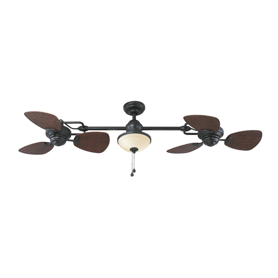
TWIN BREEZE II CEILING
Purchase Date
1
ITEM #0396772
MODEL #L0982
Español p. 20
Lowes.com/harborbreeze
FAN
Advertisement
Table of Contents

Related Manuals for Harbor Breeze L0982


Summary of Contents for Harbor Breeze L0982
- Page 1 ITEM #0396772 TWIN BREEZE II CEILING MODEL #L0982 Harbor Breeze ® is a registered trademark Español p. 20 of LF, LLC. All Rights Reserved. ATTACH YOUR RECEIPT HERE Serial Number Purchase Date Questions, problems, missing parts? Before returning to your retailer, call our customer service department at 1-800-643-0067, 8 a.m.
-
Page 2: Table Of Contents
TABLE OF CONTENTS Package Contents ......................Hardware Contents ......................Safety Information ......................Preparation ........................Initial Instructions ....................... Wiring Instructions ......................Final Instruction ........................ Operating Instructions ...................... Care and Maintenance ..................... Troubleshooting ........................ Limited Lifetime Warranty ....................Replacement Parts List ....................Lowes.com/harborbreeze... -
Page 3: Package Contents
PACKAGE CONTENTS PART DESCRIPTION QUNTITY PART DESCRIPTION QUNTITY Mounting Bracket Bulb Downrod Assembly Glass Shade Canopy Light Finial Cap Canopy Cover Light Finial Switch Housing Coupling Cover (preassembled on Motor Body (G)) Top Housing Bottom Housing (Preassembled on (preassembled on Motor Body (G)) Motor Body (G)) Light Switch Cover Motor Body... -
Page 4: Hardware Contents
HARDWARE CONTENTS (Not shown actual size) Blade Screw Wire Nut Qty. 18 + 1 Extra Motor Screw Qty. 4 Qty. 7 + 6 Extra Qty. 2 SAFETY INFORMATION READ AND SAVE THESE INSTRUCTIONS Please read and understand this entire manual before attempting to assemble, operate or install the product. . -
Page 5: Preparation
WARNING . Risk of fire. Most dwellings built before 1985 have supply wire rated for 140°F. Consult a qualified electrician before installation. . To reduce the risk of fire or electric shock, do not use this fan with any solid state fan speed device or variable speed control. -
Page 6: Initial Instructions
INITIAL INSTRUCTIONS 1. Turn off circuit breakers and wall switch to the fan supply line leads. DANGER: Failure to disconnect power supply prior to installation may result in serious injury or death. 2a. Choose the desired mounting method: A. Standard Mounting: Standard mounting is best suited for ceilings 8 ft. - Page 7 INITIAL INSTRUCTIONS 3. Check existing outlet box (not included) to ensure it is securely fastened to at least two points in a structural ceiling member and can support the full weight of the fan. Once verified, install mounting bracket (A) to the outlet box using the screws and washers provided with the outlet box.
- Page 8 INITIAL INSTRUCTIONS 6. Place downrod assembly (B) through canopy (C), canopy cover (D) and coupling cover (E). 7. Feed power wires from motor body (G) through downrod assembly (B), then insert downrod assembly (B) into the coupling on top housing (F). Align the hole on downrod assembly (B) to hole on coupling, then re-install clevis pin (U).
-
Page 9: Wiring Instructions
INITIAL INSTRUCTIONS 9. Carefully lift the assembly and rest the hanger ball of downrod assembly (B) on the mounting bracket (A) attached to the outlet box. NOTE: Unlike a standard circular fan, the mounting bracket (A) for this item does not have a tab, which locks the fan into a specific position. -
Page 10: Final Instruction
WIRING INSTRUCTIONS 2. Securely connect the fan WHITE wire to the supply GREEN WHITE wire using wire connector supplied. Securely connect the fan BLACK and BLUE wires to the supply WHITE BLACK wire using wire connector supplied. BLACK Hardware Used Black Fan Wire Wire Connector... - Page 11 FINAL INSTRUCTIONS Slide canopy cover (D) over the mounting screws visible in canopy (C). Rotate canopy cover (D) clockwise until it locks into place. NOTE: You may need to adjust the mounting screws until the canopy (C) and canopy cover (D) have a snug fit. Position one blade iron (H) under blade (I).
- Page 12 FINAL INSTRUCTIONS 5. Attach the fan switch cover (J) to switch housing (Q) on motor of motor body (G), securing with fan finial (K). Repeat for the other motor of motor body (G). 6. Remove three set screws preinstalled on bottom housing (R) of motor body (G) and save them for later use.
- Page 13 FINAL INSTRUCTIONS 8. Align the cutout on the light kit (L) with the reverse switch on the bottom housing (R). Attach the light kit (L) to the motor housing (G) using the three set screws previously removed (step 6, page 12). Tighten securely, then install bulbs (M) into each socket.
- Page 14 FINAL INSTRUCTIONS 11. For assembly without the light kit (L), remove the preassembled screw in the middle of bottom housing (R) and disassemble bottom housing (R) from motor body (G). Save screw for later use. Screw Remove the preassembled wiring harness (with pull chain, 6-pin connector and plugs) from the light kit (L).
- Page 15 FINAL INSTRUCTIONS 14. Attach the 9-pin connector preassembled on bottom housing (R) to the 9-pin connector from motor body (G). Then, re-attach the bottom housing (R) to the motor body (G) with previously removed screw (Step 11, page 14). Screw Align the cutout on the light switch cover (S) with the pull chain on the bottom housing (R).
-
Page 16: Operating Instructions
OPERATING INSTRUCTIONS The fob (DD) marked with a fan image is for motor speed control: High, Medium, Low and Off. Pull once for each position. The fob (DD) marked with a lamp image controls the light either On or Off with each pull of the chain. When the season changes, you may want to chang the direction the fan spins. -
Page 17: Care And Maintenance
CARE AND MAINTENANCE Important: Shut off main power supply before beginning any maintenance. Do not use water or a damp cloth to clean the ceiling fan. . At least twice each year, tighten all screws and lower canopy to check mounting plate screws. . -
Page 18: Limited Lifetime Warranty
TROUBLESHOOTING PROBLEM PROBABLE CAUSE CORRECTIVE ACTION 7. Fan Blade out of balance. 7. Interchange two adjacent blades; this will redistribute the weight and possibly result in smoother operation. Or, refer to the instructions inside the balance kit (S). 8. Fan too close to vaulted ceiling. 8. -
Page 19: Replacement Parts List
A124-0143293 Blade Iron A143-0159293 Wire Connector Blade A141-0331001 Blade Screw B168-0400070 Fan Switch Cover A122-0096293 Motor Screw Fan Finial A186-0096293 Light Kit A187-0245293 Printed in China Harbor Breeze ® is a registered trademark of LF, LLC. All Rights Reserved. Lowes.com/harborbreeze...
Need help?
Do you have a question about the L0982 and is the answer not in the manual?
Questions and answers