
Related Manuals for Vega VEGABAR 64


Summary of Contents for Vega VEGABAR 64
-
Page 1: Operating Instructions
Operating Instructions VEGABAR 64 Foundation Fieldbus Document ID: 28259 Process pressure/ Hydrostatic... -
Page 2: Table Of Contents
Setup with PACTware and other adjustment programs Connecting the PC ......45 VEGABAR 64 • Foundation Fieldbus... - Page 3 To ensure reliable setup and operation of your instrument, we offer accessories and replacement parts. The corresponding instructions manuals are: 32036 - Welded socket and seals 27720 - External indication VEGADIS 61 34296 - Protective cover 30175 - Electronics module VEGABAR series 50 and 60 VEGABAR 64 • Foundation Fieldbus...
-
Page 4: About This Document
This symbol indicates special instructions for Ex applications. List The dot set in front indicates a list with no implied sequence. à Action This arrow indicates a single action. Sequence Numbers set in front indicate successive steps in a procedure. VEGABAR 64 • Foundation Fieldbus... -
Page 5: For Your Safety
During work on and with the device the required personal protective equipment must always be worn. 2.2 Appropriate use VEGABAR 64 is a pressure transmitter for measurement of gauge pressure, absolute pressure and vacuum. You can find detailed information on the application range in chapter "Product description". -
Page 6: Safety Approval Markings And Safety Tips
The range of available functions depends on the respective software version of the individual components. The software version of VEGABAR 64 can be determined as follows: via PACTware on the type label of the electronics via the indicating and adjustment module You can view all software histories on our website www.vega.com. - Page 7 2 For your safety Chapter "Packaging, transport and storage" Chapter "Disposal" VEGABAR 64 • Foundation Fieldbus...
-
Page 8: Product Description
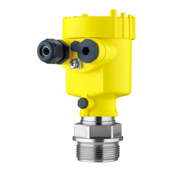
Housing cover, optionally available with indicating and adjustment module PLICSCOM The components are available in different versions. Fig. 1: Example of a VEGABAR 64 with process fitting G1½ A and plastic housing Housing cover with integrated PLICSCOM (optional) Housing with electronics Process fitting with measuring cell... -
Page 9: Principle Of Operation
In addition to the type label outside, you can also find the serial number on the inside of the instrument. 3.2 Principle of operation VEGABAR 64 is a pressure transmitter for use in the paper, food Application area processing and pharmaceutical industries as well as in water/sewage water plants. -
Page 10: Operation
Foundation Fieldbus". The appropriate certificates are also available there. A CD with the appropriate files and certificates can be ordered via e-mail under info@de.vega.com or by phone from one of the VEGA agencies under the order number "DRIVER.S". The backlight of the indicating and adjustment module is powered by the sensor. - Page 11 Not exposed to corrosive media Protected against solar radiation Avoiding mechanical shock and vibration Storage and transport temperature see chapter "Supplement - Storage and transport temperature Technical data - Ambient conditions" Relative humidity 20 … 85 % VEGABAR 64 • Foundation Fieldbus...
-
Page 12: Mounting
Ventilation for the measuring cell is realised by means of a filter element in the socket of the electronics housing. Ventilation for the electronics housing is realised via an additional filter element in the area of the cable glands. VEGABAR 64 • Foundation Fieldbus... - Page 13 Temperature limits Higher process temperatures often mean also higher ambient temperatures. Make sure that the upper temperature limits stated in chapter "Technical data" for the environment of the electronics housing and connection cable are not exceeded. VEGABAR 64 • Foundation Fieldbus...
-
Page 14: Mounting Steps
4 Mounting Fig. 4: Temperature ranges Process temperature Ambient temperature 4.2 Mounting steps For mounting VEGABAR 64, a welded socket is required. You can find Welding the socket these components in the supplementary instructions manual "Welded socket and seals". Sealing/Screwing in Seal the thread with teflon, hemp or a similar resistant seal material on... - Page 15 The socket housing can be displaced by 180° to the wall mounting plate. Warning: The four screws of the socket housing must only be hand-screwed. A torque > 5 Nm (3.688 lbf ft) can damage the wall mounting plate. VEGABAR 64 • Foundation Fieldbus...
-
Page 16: Connecting To Power Supply
Connect only in the complete absence of line voltage If overvoltage surges are expected, overvoltage arresters should be installed according to Foundation Fieldbus specification Tip: We recommend VEGA overvoltage arrester B63-32. Take note of In hazardous areas you should take note of the appropriate safety instruc- regulations, conformity and type approval certificates of the sensors... -
Page 17: Connection Procedure
10 Connect the screen to the internal ground terminal, connect the outer ground terminal with potential equalisation 11 Tighten the compression nut of the cable entry. The seal ring must completely encircle the cable 12 Screw the housing cover on VEGABAR 64 • Foundation Fieldbus... - Page 18 The electrical connection is finished. Fig. 6: Connection steps 6 and 7 IP 68 version with exter- Proceed as follows: nal housing Loosen the four screws on the housing socket with an Allen key size 4 VEGABAR 64 • Foundation Fieldbus...
- Page 19 Remove approx. 5 cm of the cable mantle, strip approx. 1 cm insulation from the ends of the individual wires. After shortening the cable, fasten the type plate with sup- port back onto the cable. VEGABAR 64 • Foundation Fieldbus...
-
Page 20: Wiring Plan, Single Chamber Housing
5.3 Wiring plan, single chamber housing The following illustrations apply to the non-Ex as well as to the Ex-ia version. Housing overview Fig. 8: Material versions, single chamber housing Plastic Aluminium Stainless steel Stainless steel casting VEGABAR 64 • Foundation Fieldbus... -
Page 21: Wiring Plan, Double Chamber Housing
Wiring plan Display I 2 C Fig. 10: Wiring plan, single chamber housing Voltage supply/Signal output 5.4 Wiring plan, double chamber housing The following illustrations apply to the non-Ex as well as to the Ex-ia version. VEGABAR 64 • Foundation Fieldbus... - Page 22 Display I ² C 5 6 7 8 Fig. 12: Electronics compartment, double chamber housing Simulation switch ("on" = mode for simulation release) Connection for VEGACONNECT (I²C interface) Internal connection cable to the connection compartment VEGABAR 64 • Foundation Fieldbus...
- Page 23 Fig. 13: Connection compartment, double chamber housing Plug connector for VEGACONNECT (I²C interface) Ground terminal for connection of the cable screen Spring-loaded terminals for voltage supply Wiring plan I 2 C Fig. 14: Wiring plan, double chamber housing Voltage supply/Signal output VEGABAR 64 • Foundation Fieldbus...
-
Page 24: Wiring Plan Double Chamber Housing Ex D
Display I ² C 5 6 7 8 Fig. 16: Electronics compartment, double chamber housing Simulation switch ("on" = mode for simulation release) Connection for VEGACONNECT (I²C interface) Internal connection cable to the connection compartment VEGABAR 64 • Foundation Fieldbus... -
Page 25: Wiring Plan - Version Ip 66/Ip 68, 1 Bar
Wiring plan Fig. 18: Wiring plan double chamber housing Ex d Voltage supply/Signal output 5.6 Wiring plan - version IP 66/IP 68, 1 bar This version is only available for instruments with absolute pressure measuring ranges. VEGABAR 64 • Foundation Fieldbus... -
Page 26: Wiring Plan, External Housing With Version Ip 68
(+) and blue (-) to power supply or to the processing system Shielding 5.7 Wiring plan, external housing with version IP 68 Overview Fig. 20: VEGABAR 64 in IP 68 version 25 bar, non-Ex and axial cable outlet, external housing VEGABAR 64 • Foundation Fieldbus... - Page 27 Spring-loaded terminals for connection of the external indication VEGADIS Cable gland to VEGABAR Ground terminal for connection of the cable screen Spring-loaded terminals for Foundation Fieldbus connection Simulation switch ("on" = mode for simulation release) VEGABAR 64 • Foundation Fieldbus...
- Page 28 1 2 3 4 Fig. 22: Connection of the sensor in the housing socket Brown Blue Yellow White Shielding Breather capillaries Wiring plan external electronics Display I 2 C Fig. 23: Wiring plan external electronics Power supply VEGABAR 64 • Foundation Fieldbus...
-
Page 29: Switch On Phase
5 Connecting to power supply 5.8 Switch on phase After VEGABAR 64 is connected to voltage supply or after voltage Switch on phase recurrence, the instrument carries out a self-check for approx. 30 seconds. The following steps are carried out: Internal check of the electronics Indication of the instrument type, the firmware as well as the... -
Page 30: Set Up With The Indicating And Adjustment Module Plicscom
Screw housing cover with inspection window tightly back on Removal is carried out in reverse order. The indicating and adjustment module is powered by the sensor, an additional connection is not necessary. VEGABAR 64 • Foundation Fieldbus... - Page 31 Fig. 24: Mounting the indicating and adjustment module Note: If you intend to retrofit the instrument with an indicating and adjustment module for continuous measured value indication, a higher cover with an inspection glass is required. VEGABAR 64 • Foundation Fieldbus...
-
Page 32: Adjustment System
The functions of the individual keys are shown in the above illustration. Approx. 10 minutes after the last pressing of a key, an automatic reset to measured value indication is triggered. Any values not confirmed with [OK] will not be saved. VEGABAR 64 • Foundation Fieldbus... -
Page 33: Setup Procedure
6 Set up with the indicating and adjustment module PLICSCOM 6.4 Setup procedure VEGABAR 64 can be used for level as well as for process pressure Level or process pres- sure measurement measurement. Default setting is level measurement. The mode can be changed in the adjustment menu. - Page 34 Select the requested unit, e.g. kg/dm³ with [->] and confirm with [OK], the submenu "Density" appears. Unit of measurement Density 0001000 kg/dm³ Enter the requested density value with [->] and [+], confirm with [OK] and move to position correction with [->]. VEGABAR 64 • Foundation Fieldbus...
- Page 35 Information: For an adjustment with filling, you simply enter the displayed actual measured value. If the adjustment ranges are exceeded, the message "Outside parameter limits" appears. The editing procedure can be Selection options: °C, °F. VEGABAR 64 • Foundation Fieldbus...
- Page 36 "Outside parameter limits" appears. The editing procedure can be aborted with [ESC] or the displayed limit value can be accepted with [OK]. Process pressure measurement Set up VEGABAR 64 in the following sequence: Parameter ad- justment "Proc- Select application "Process pressure measurement"...
- Page 37 The actual measured value is displayed in addition to the menu items for zero/span adjustment. VEGABAR 64 is preset to application "Level measurement". Proceed Select application as follows when switching over to application "Process pressure "Process pressure...
- Page 38 Accept Edit Confirm with [OK] and move to min.(zero) adjustment with [->]. Carrying out zero ad- Proceed as follows: justment Edit the mbar value in the menu item "zero" with [OK]. Selection options: °C, °F. VEGABAR 64 • Foundation Fieldbus...
- Page 39 For an adjustment with pressure, you simply enter the displayed actual measured value. If the adjustment ranges are exceeded, the message "Outside parameter limits" appears. The editing procedure can be aborted with [ESC] or the displayed limit value can be accepted with [OK]. VEGABAR 64 • Foundation Fieldbus...
- Page 40 AI-Out The values of the following menu items are not reset with "Reset: Menu section Function Reset value Basic settings Position correction no reset Display Lighting no reset Service Language no reset Sensor-specific basic adjustment. VEGABAR 64 • Foundation Fieldbus...
- Page 41 You will find a detailed description of these menu items in the operating instructions manual "Indicating and adjustment module". Special parameters are parameters which are set customer-specifically on the service level with the adjustment software PACTware. VEGABAR 64 • Foundation Fieldbus...
-
Page 42: Menu Schematic
Displayed value Lighting ▼ AI-Out Switched off Diagnostics Basic adjustment Display ▶ Diagnostics Service Info 3.3.1 Pointer Sensor status Trend curve p-min.: -5.8 mbar p-max.: 167.5 mbar Start trend curve? T-min.: -12.5 °C T-max.: +85.5 °C VEGABAR 64 • Foundation Fieldbus... - Page 43 Display Diagnostics Service ▶ Info Device-ID Sensor type Date of manufacture Last change using PC e.g. 16. May 2008 Sensor-TAG Software version e.g. 3.50 e.g. 16. May 2008 Serial number 12345678 Sensor characteristics Display now? VEGABAR 64 • Foundation Fieldbus...
-
Page 44: Saving The Parameter Adjustment Data
They are hence available for multiple use or service purposes. If VEGABAR 64 is equipped with an indicating and adjustment module, the most important data can be read out of the sensor into indicating and adjustment module. -
Page 45: Connecting The Pc
USB cable to the PC VEGACONNECT Sensor External connection via I²C interface TWIST Fig. 27: Connection via I²C connection cable I²C bus (com.) interface on the sensor I²C connection cable of VEGACONNECT VEGACONNECT USB cable to the PC VEGABAR 64 • Foundation Fieldbus... -
Page 46: Parameter Adjustment With Pactware
A detailed description is available in the online help of PACTware and the VEGA DTMs. Note: Keep in mind that for setup of VEGABAR 64, DTM-Collection in the actual version must be used. All currently available VEGA DTMs are provided in the DTM Collection on CD and can be obtained from the responsible VEGA agency for a token fee. -
Page 47: Maintenance And Fault Rectification
24 hour service hotline However, should these measures not be successful, call the VEGA service hotline in urgent cases under the phone no. +49 1805 858550. The hotline is available to you 7 days a week round-the-clock. Since we offer this service world-wide, the support is only available in the... - Page 48 Depending on the failure reason and measures taken, the steps described in chapter "Set up" must be carried out again, if necessary. tification Fault message can also appear if the pressure is higher than the nominal range. VEGABAR 64 • Foundation Fieldbus...
-
Page 49: Calculation Of Total Deviation (Similar To Din 16086)
Pressure measurement in the pipeline 8 bar (800 KPa) Example Product temperature 50 °C, hence within the compensated range VEGABAR 64 with measuring range 25 bar Calculation of the set Turn Down: TD = 10 bar/8 bar, TD = 1.25 Basic accuracy digital output signal in percent: = √((F... -
Page 50: Exchanging The Electronics Module
These are not included in the electronics module without serial number. The serial number is stated on the type label of VEGABAR 64 or on the delivery note. 8.5 Software update... -
Page 51: Instrument Repair
Connect the sensor to power supply and provide connection from PC to the instrument via VEGACONNECT. Start PACTware and provide connection to the sensor, e.g. via the VEGA project assistant. Close the parameter window of the sensor, as far as open. -
Page 52: Dismounting
Correct disposal avoids negative effects to persons and environment and ensures recycling of useful raw materials. Materials: see chapter "Technical data" If you have no possibility to dispose of the old instrument professionally, please contact us concerning return and disposal. VEGABAR 64 • Foundation Fieldbus... -
Page 53: Supplement
Connection between IP 68 transmitter PUR, FEP, PE and external electronics housing Type plate support with IP 68 version on PE hard cable 0.8 … 8 kg (1.764 … 17.64 lbs), depending on Weight approx. process fitting VEGABAR 64 • Foundation Fieldbus... - Page 54 Damping (63 % of the input variable) Additional output parameter - temperature Processing is made via output signal HART multidrop, Profibus PA and Foundation Fieldbus -50 … +150 °C (-58 … +302 °F) Range 1 °C (1.8 °F) Resolution VEGABAR 64 • Foundation Fieldbus...
- Page 55 -0.4 bar/-40 kPa -0.2 … 0.2 bar/-20 … 20 kPa 30 bar/3000 kPa -0.8 bar/-80 kPa -0.5 … 0.5 bar/-50 … 50 kPa 35 bar/3500 kPa -1 bar/-100 kPa Values less than -1 bar cannot be set. VEGABAR 64 • Foundation Fieldbus...
- Page 56 500 psi 0 psi 0 … 35 psi 700 psi 0 psi 0 … 70 psi 900 psi 0 psi 0 … 150 psi 1300 psi 0 psi 0 … 350 psi 1900 psi 0 psi VEGABAR 64 • Foundation Fieldbus...
- Page 57 < (0.05 % + 0.1 % x TD) In the compensated temperature range 0 … +100 °C (+32 … +212 °F) < (0.05 % + 0.15 % x TD) Outside the compensated temperature range Incl. non-linearity, hysteresis and non-repeatability. VEGABAR 64 • Foundation Fieldbus...
- Page 58 -20 … +150 °C (-4 … +302 °F) FKM (VP2/A) EPDM (A+P 75.5/KW75F) -40 … +150 °C (-40 … +302 °F) With process fitting PVDF, max. 100 °C (212 °F). VEGABAR 64 • Foundation Fieldbus...
- Page 59 Spring-loaded terminals for wire cross-sec- tion Tested according to the regulations of German Lloyd, GL directive 2. Tested according to EN 60068-2-27. Depending on the version M12 x 1, according to DIN 43650, Harting, 7/ 8" FF. VEGABAR 64 • Foundation Fieldbus...
- Page 60 1 x plug (depending on the version), 1 x blind stopper M20 x 1.5 2.5 mm² (AWG 14) Spring-loaded terminals for wire cross-sec- tion up to Depending on the version M12 x 1, according to DIN 43650, Harting, 7/ 8" FF. VEGABAR 64 • Foundation Fieldbus...
- Page 61 12 … 32 V DC Non-Ex instrument 12 … 24 V DC EEx-ia instrument 12 … 32 V DC EEx-id instrument Power supply by/max. number of sensors max. 32 (max. 10 with Ex) H1 power supply VEGABAR 64 • Foundation Fieldbus...
- Page 62 Depending on the version, instruments with approvals can have different technical data. For these instruments, the corresponding approval documents have to be taken into account. These are part of the delivery or can be downloaded under www.vega.com via "VEGA Tools" and "serial number search" as well as via "Downloads" and "Approvals".
-
Page 63: Information On Foundation Fieldbus
Channel = 2: Secondary Value 1 Channel = 3: Secondary Value 2 AI 3 Channel = 4: Temperature Fig. 29: Transducer Block VEGABAR 64 TB Transducer Block Function Block (AI =Analogue Input) Diagram, adjustment The following illustration shows the function of the adjustment:... - Page 64 Sensor_value scale_in_0 scale_in_100 -0,500 0,500 Fig. 30: Adjustment VEGABAR 64 Parameter list The following list contains the most important parameters and their meaning: primary_value Process Value after min/max-adjustment and linearization. Selected as input to AIFB by setting 'Channel' = 1. Unit derives from 'Primary_value_unit'...
- Page 65 Holds the maximum sensor value. Write access resets to current value. Unit derives from 'Sensor_range.unit' Write access resets to current value min_peak_sensor_value Holds the minimum sensor value. Write access resets to current value. Unit derives from 'Sensor_range.unit' Write access resets to current value CAL_POINT_HI VEGABAR 64 • Foundation Fieldbus...
- Page 66 Holds the maximum process temperature. Write access resets to current value. Unit derives from 'Temperature.unit' Write access resets to current value min_peak_temperature_value Holds the minimum process temperature. Write access resets to current value. Unit derives from 'Temperature.unit' Write access resets to current value VEGABAR 64 • Foundation Fieldbus...
-
Page 67: Dimensions
ø 84 mm (3.31") M16x1,5 M20x1,5/ M20x1,5 ½ NPT M20x1,5/ ½ NPT Fig. 31: Housing versions (with integrated PLICSCOM the housing is 9 mm/0.35 in higher) Plastic housing Stainless steel housing Aluminium double chamber housing Aluminium housing VEGABAR 64 • Foundation Fieldbus... - Page 68 Fig. 32: Housing versions in protection IP 66/IP 68, 1 bar (with integrated indicating and adjustment module the housing is 9 mm/0.35 in higher) Stainless steel housing Special steel casting housing Aluminium double chamber housing Aluminium housing VEGABAR 64 • Foundation Fieldbus...
- Page 69 65 mm ") 42mm ") 40mm ") 90 mm (3 ") 110 mm (4 ") ~ 66 mm (2 ") Fig. 33: IP 68 version with external housing - non-Ex Lateral cable outlet Axial cable outlet VEGABAR 64 • Foundation Fieldbus...
- Page 70 GO/GR Fig. 34: VEGABAR 64 - threaded fitting: GV/GT/GH = G½ A manometer connection EN 837, GJ/GK/GM/GU = G½ A inner G¼ A, GS = G½ A inner G¼ A PVDF, GI = G½ A manometer connection volume-reduced, GO/GR = ½ NPT, BF = M20 x 1.5 manometer connection EN 837...
- Page 71 ") ") Fig. 35: VEGABAR 64 - threaded fitting: GC = G1 A, GD = G1¼ A, GG = G1½ A, GW = G1½ A PVDF, GE = G2 A, GN = 1½ NPT For the version with temperature range up to 150 °C/302 °F, the measure of length increases by 28 mm (1.1 in).
- Page 72 ø 105 mm ") Fig. 36: VEGABAR 64 - hygienic fitting: CD/CC = Tri-Clamp 1"/Tri-Clamp 1½", CA = Tri-Clamp 2", CA = Tri-Clamp 2½", LA = hygienic fitting with compression nut F40, AA = DRD VEGABAR 64 • Foundation Fieldbus...
- Page 73 RS/RT Fig. 37: VEGABAR 64 - hygienic fitting: TA = Tuchenhagen Varivent DN 32, TB = Tuchenhagen Varivent DN 25, RA/RB = bolting DN 40/DN 50 according to DIN 11851, RD = bolting DN 50 according to DIN 11864, RS/RT = SMS DN 38/DN 51 VEGABAR 64 •...
- Page 74 " 6“ 4xø 5“ " " " " 4” 12xø 15” " " " " " Fig. 38: VEGABAR 64 - flange connection Flange connection according to DIN 2501 Flange fitting according to ANSI B16.5 VEGABAR 64 • Foundation Fieldbus...
- Page 75 " 4“ 150 lbs 9 " " " 4xø " " " " Fig. 39: VEGABAR 64 - flange connection with extension Flange connection according to DIN 2501 Flange fitting according to ANSI B16.5 Order-specific VEGABAR 64 • Foundation Fieldbus...
- Page 76 10 Supplement VEGABAR 64 - threaded fitting for paper industry M56x1,25 M44x1,25 BA/BB Fig. 40: VEGABAR 64 - threaded fitting for the paper industry: BA/BB = M44 x 1,25, BE = M56 x 1,25 VEGABAR 64 • Foundation Fieldbus...
- Page 77 50 mm ") Fig. 41: VEGABAR 64 - extension fitting for paper industry: EV/FT = absolutely flush for pulper (EV: flange 2-times flattened), FG = extension for ball valve fitting, EW = flange for manometer lug VEGABAR 64 • Foundation Fieldbus...
-
Page 78: Industrial Property Rights
Les lignes de produits VEGA sont globalement protégées par des droits de propriété intellectuelle. Pour plus d'informations, on pourra se référer au site http://www.vega.com VEGA lineas de productos están protegidas por los derechos en el campo de la propiedad industrial. Para mayor información revise la pagina web http://www.vega.com Линии... - Page 79 10 Supplement VEGABAR 64 • Foundation Fieldbus...
- Page 80 All statements concerning scope of delivery, application, practical use and operating conditions of the sensors and processing systems correspond to the information avail- able at the time of printing. © VEGA Grieshaber KG, Schiltach/Germany 2008 28259-EN-081209 Subject to change without prior notice...
Need help?
Do you have a question about the VEGABAR 64 and is the answer not in the manual?
Questions and answers