
Related Manuals for Arcus PMX-4EX-SA


Summary of Contents for Arcus PMX-4EX-SA
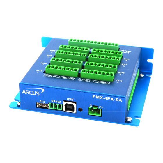
- Page 1 PMX-4EX-SA Advanced 4-Axis Stepper Motion Controller PMX-4EX-SA Manual page 1 Rev 3.11...
- Page 2 3.02 – 5 Revision 3.10 – 6 Revision 3.11 – 7 Revision Firmware Compatibility: V180BL † †If your module’s firmware version number is less than the listed value, contact Arcus for the appropriate documentation. PMX-4EX-SA Manual page 2 Rev 3.11...
-
Page 3: Table Of Contents
EATURES 1.2. M ..........................7 ODEL UMBERS 1.2.1. Top Board Options ........................7 2. Electrical Specifications ..................8 3. Dimensions ....................... 9 3.1. PMX-4EX-SA-TBS D IMENSIONS ..................... 9 3.2. PMX-4EX-SA-TB9 D ....................10 IMENSIONS 4. Connectivity ....................11 4.1. 2-P (5.08... - Page 4 7.2.1. DXF Viewer ..........................76 7.2.2. Status ............................76 7.2.3. Control ............................ 77 7.2.4. DXF Action ..........................77 7.2.5. Motion Conversion Program ....................79 7.2.6. DXF Converter – Important Notes ..................79 8. ASCII Language Specification ................ 81 PMX-4EX-SA Manual page 4 Rev 3.11...
- Page 5 9.2.7. Standalone Example Program 7 – Multi Thread............... 93 9.2.8. Standalone Example Program 8 – Multi Thread............... 94 A: Speed Settings ....................95 A.1. A CCELERATION ECELERATION ANGE ..................95 A.2. A – P CCELERATION ECELERATION ANGE OSITIONAL ............96 PMX-4EX-SA Manual page 5 Rev 3.11...
-
Page 6: Introduction
PMX-4EX-SA is an advanced 4 axis stepper standalone programmable motion controller. Communication to the PMX-4EX-SA can be established over USB or RS-485. It is possible to download a standalone program to the device and have it run independent of a host. -
Page 7: Model Numbers
4EX – 4-axis enhanced controller 1.2.1. Top Board Options The PMX-4EX-SA is available in two different top board configurations. The top board should be selected depending on your interfacing needs. The standard top board option (TBS) consists of 3.81mm screw terminals for X/Y/Z/U pulse/dir/enable outputs and alarm inputs. -
Page 8: Electrical Specifications
Digital Output Source Current Operating Temperature ° C Storage Temperature +150 ° C Table 2.0 Only applicable to the TB9 top board option. Current requirement is dependent on the driver settings Based on component ratings PMX-4EX-SA Manual page 8 Rev 3.11... -
Page 9: Dimensions
3. Dimensions 3.1. PMX-4EX-SA-TBS Dimensions Figure 3.0 PMX-4EX-SA Manual page 9 Rev 3.11... -
Page 10: Pmx-4Ex-Sa-Tb9 Dimensions
3.2. PMX-4EX-SA-TB9 Dimensions Figure 3.1 PMX-4EX-SA Manual page 10 Rev 3.11... -
Page 11: Connectivity
4. Connectivity In order for PMX-4EX-SA to operate, it must be supplied with +12VDC to +24VDC. Power pins as well as communication port pin outs are shown below. Figure 4.0 4.1. 2-Pin Power Connector (5.08mm) Pin # In/Out Name Description... -
Page 12: 10-Pin Aio Connector (2.0Mm)
4.4. 10-Pin DI Connector (3.81mm) Figure 4.3 Pin # In/Out Name Description Opto-Supply +12V to +24 VDC (for digital IO) Opto-Ground (for digital IO) Digital Input 1 Digital Input 2 Digital Input 3 Digital Input 4 PMX-4EX-SA Manual page 12 Rev 3.11... -
Page 13: 8-Pin Do Connector (3.81Mm)
Digital Output 6 Digital Output 7 Digital Output 8 Table 4.4 Mating Connector Description: 8 pin 0.15” (3.81mm) connector Mating Connector Manufacturer: On-Shore Mating Connector Manufacturer Part: EDZ1550/8 Other 3.81 compatible connectors can be used. PMX-4EX-SA Manual page 13 Rev 3.11... -
Page 14: 14-Pin Motion Inputs Connector (3.81Mm)
-Limit [X Axis] Home [X Axis] +Limit [X Axis] Table 4.5 Mating Connector Description: 14 pin 0.15” (3.81mm) connector Mating Connector Manufacturer: On-Shore Mating Connector Manufacturer Part: EDZ1550/14 Other 3.81 compatible connectors can be used. PMX-4EX-SA Manual page 14 Rev 3.11... -
Page 15: 8-Pin Encoder Connectors (3.81Mm)
/A Channel Encoder Input A Channel Encoder Input Table 4.6 Mating Connector Description: 8 pin 0.15” (3.81mm) connector Mating Connector Manufacturer: On-Shore Mating Connector Manufacturer Part: EDZ1550/8 Other 3.81 compatible connectors can be used PMX-4EX-SA Manual page 15 Rev 3.11... -
Page 16: 8-Pin Tbs Axis Connectors (3.81Mm)
Alarm No Connection No Connection Enable Direction Pulse Table 4.7 Mating Connector Description: 8 pin 0.15” (3.81mm) connector Mating Connector Manufacturer: On-Shore Mating Connector Manufacturer Part: EDZ1550/8 Other 3.81 compatible connectors can be used. PMX-4EX-SA Manual page 16 Rev 3.11... -
Page 17: 9-Pin Tb9 Axis Connectors (D-Sub 9)
Alarm Input (5V TTL) Reserved. Do not make connection. Driver Ground Direction Reserved. Do not make connection. Table 4.8 The pins on the DB9 headers can be connected directly to a DMX-A2-DRV module (pin-to-pin compatible) PMX-4EX-SA Manual page 17 Rev 3.11... -
Page 18: 2-Pin Tb9 Power Connectors (5.08Mm)
There are two separate driver power inputs. The right side is for axes X + Z. The left side is for axes Y + U. The power requirement will be dependent on the driver specifications for each axis. PMX-4EX-SA Manual page 18 Rev 3.11... -
Page 19: Pmx-4Ex-Sa Interface Circuit
4.11. PMX-4EX-SA Interface Circuit Figure 4.10 PMX-4EX-SA Manual page 19 Rev 3.11... -
Page 20: Pulse, Direction, And Enable Outputs
Each output is capable of sinking up to 40mA of current. Figure 4.11 Figure 4.12 shows an example wiring diagram between the pulse, direction, and enable outputs on the PMX-4EX-SA and the corresponding input on a typical stepper driver. Figure 4.12... -
Page 21: Limit, Home, And Digital Inputs
When the digital input is pulled to ground, current will flow from the opto-supply to ground, turning on the opto-isolator and activating the input. To de-activate the input, the digital input should be left unconnected or pulled up to the opto-supply, preventing current from flowing through the opto-isolator. PMX-4EX-SA Manual page 21 Rev 3.11... -
Page 22: Digital Outputs
When using single-ended encoders, use the /A, /B, and /Z inputs. +5V supply and Ground signals are available to power the encoder. Make sure that the total current usage is less than 200mA for the +5V. The maximum encoder frequency is 5MHz. PMX-4EX-SA Manual page 22 Rev 3.11... -
Page 23: Communication Interface
All USB communication will be done using an ASCII command protocol. 5.1.1. Typical USB Setup The PMX-4EX-SA can be connected to a PC directly via USB or through a USB hub. All USB cables should have a noise suppression choke to avoid communication loss or interruption. -
Page 24: Usb Communication Issues
A common problem that users may have with USB communication is that after sending a command from the PC to the device, the response is not received by the PC until another command is sent. In this case, the data buffers between the PMX-4EX-SA Manual page 24 Rev 3.11... -
Page 25: Serial Communication
Figure 5.1 5.2. Serial Communication The PMX-4EX-SA has the ability to communicate over an RS-485 interface using an ASCII protocol. An RS-485 serial port on the PC or PLC can be used to communicate with the PMX-4EX-SA. A USB to RS-485 converter can also be used. -
Page 26: Communication Port Settings
None Stop Bit Table 5.0 PMX-4EX-SA provides the user with the ability to set the desired baud rate of the serial communication. In order to make these changes, first set the desired baud rate by using the DB command. Return Value... -
Page 27: Rs-485 Communication Issues
For an RS-485 network, it may be required that a 120 Ohm resistor is placed in between the 485+ and 485- signals, at the beginning and end of the bus. A terminal resistor will help eliminate electrical reflections on the RS-485 network. PMX-4EX-SA Manual page 27 Rev 3.11... -
Page 28: Device Number
This will allow the PC to differentiate between multiple controllers. This is applicable for both USB and RS-485 communication types. In order to make this change to a PMX-4EX-SA, first store the desired number using the DN command. Note that this value must be within the range [4EX00,4EX99]. -
Page 29: General Operation Overview
USB. Standalone commands are used when writing a standalone program onto the PMX-4EX-SA. 6.1. Motion Profile By default, the PMX-4EX-SA uses trapezoidal velocity profile as shown in figure 6.0. Figure 6.0 S-curve velocity profile can also be achieved by using the SCV[axis] command. - Page 30 Once a move command is issued, the global speed settings for the low speed and deceleration while using the individual X-axis speed settings for the high speed and acceleration. ASCII ACC DEC HSn ACCn DECn EDEC SCV Standalone HSPD LSPD ACC DEC HSPDn LSPDn ACCn DECn PMX-4EX-SA Manual page 30 Rev 3.11...
-
Page 31: Pulse Speed
The SSPD[axis]=[speed] command can be used to perform the actual speed change. For non on-the-fly speed change moves, set the speed window to 0. ASCII SSPDM[axis] SSPD[axis] Standalone SSPDM[axis] SSPD[axis] PMX-4EX-SA Manual page 31 Rev 3.11... -
Page 32: Motor Position
6.4. Motor Position The PMX-4EX-SA has a 32 bit signed step position counter for each axis. Range of the position counter is from –2,147,483,648 to 2,147,483,647. Motor positions can be read using the ASCII command PP, which returns the pulse position of all 4 axes. -
Page 33: Jog Move
Standalone ABORT ABORT[axis] STOP STOP[axis] 6.8. Positional Moves The PMX-4EX-SA can perform positional moves for individual axis. Multiple axis can also be commanded to move to a specified position in order to perform linear coordinated motion. PMX-4EX-SA Manual page 33... -
Page 34: On-The-Fly Target Position Change
1000 if performed in absolute mode. 6.8.2. Interpolated Position Moves The PMX-4EX-SA can perform interpolated motion for up to 4 axis. A single move command will use the X, Y, Z, and U commands and can consist of up to 4 target positions (one for each axis). -
Page 35: Arc Interpolation Moves
Standalone CIRP[X]:[Y] CIRN[X]:[Y] 6.11. Arc Interpolation Moves PMX-4EX-SA supports arc interpolation moves using the ARCP and ARCN commands. Arcs are drawn using X,Y axes only. The Z and U axis are not support for arc interpolation. ARCP[X]:[Y]:[θ] – Draw arc in CW direction where [X][Y] signifies X,Y position of the arc center and θ... - Page 36 Figure 6.4 will show the difference between issuing the ARCP0:0:90000 and the ARCN0:0:90000 command if both cases have the same starting point at the 0° . Figure 6.4 ASCII θ θ ARCP[X]:[Y]:[ ARCN[X]:[Y]:[ Standalone θ θ ARCP[X]:[Y]:[ ARCN[X]:[Y]:[ PMX-4EX-SA Manual page 36 Rev 3.11...
-
Page 37: Buffered Interpolation Moves
The buffered move operation cannot be used while StepNLoop is enabled. The motor status of the PMX-4EX-SA contains the status of the buffer operation. See section 6.15 for more information on this. In ASCII mode, a buffered move command will have the syntax I[X pos]:[Y pos]:[Z pos]:[speed]. -
Page 38: Homing
Instead, an error response is returned. See table 9.1 for details on error responses. The PMX-4EX-SA has five different homing routines. In ASCII mode, use the H command to perform a home move. The syntax for the home command in ASCII mode can be found below. -
Page 39: Mode 1: Limit Only
C. The motor will start moving in the opposite direction at the low speed setting until the limit input is cleared. D. Once the specified limit input is cleared, the motor will immediately stop and mark the zero reference position. ASCII H[axis][+/-]1 Standalone LHOME[axis][+/-] PMX-4EX-SA Manual page 39 Rev 3.11... -
Page 40: Mode 2: Home Input And Z-Index
C. After the home input is triggered, the motor begins to search for the z- index pulse. D. Once the z-index pulse is found, the motor immediately stops and the position is set to zero. ASCII H[axis][+/-]2 Standalone ZHOME[axis][+/-] PMX-4EX-SA Manual page 40 Rev 3.11... -
Page 41: Mode 3: Z-Index Only
A. Issuing the command starts the motor at low speed. The motor will not use the high speed setting when performing this homing routine. B. Once the z-index pulse is found, the motor stops and the position is set to zero. H[axis][+/-]3 ASCII Standalone ZOME[axis][+/-] PMX-4EX-SA Manual page 41 Rev 3.11... -
Page 42: Mode 4 : Home Input Only (High Speed And Low Speed)
If the alarm input for an axis is triggered during movement in either direction, the motor will immediately stop and the motor status bit for alarm error is set. Each axis will have its own designated alarm input. PMX-4EX-SA Manual page 42 Rev 3.11... -
Page 43: Motor Status
This command returns the motor status for all axes, as well as other information. The MST return value has the following format: [Motor Status X]: [Motor Status Y]: [Motor Status Z]: [Motor Status U]: [Buffer enabled]: PMX-4EX-SA Manual page 43 Rev 3.11... -
Page 44: Digital Inputs/Outputs
Move mode – The current move mode for positional moves (0: ABS, 1: INC) 6.16. Digital Inputs/Outputs PMX-4EX-SA module comes with 8 digital inputs and 8 digital outputs. 6.16.1. Digital Inputs The digital input status of all 8 available inputs can be read with the DI command. -
Page 45: Digital Outputs
Standalone 6.17. High Speed Latch Inputs The PMX-4EX-SA module provides the following high speed position latch inputs. This feature will allow the controller to perform a high speed position capture of both pulse and encoder counters based on a digital input trigger. -
Page 46: Sync Outputs
LTE[axis] Standalone 6.18. Sync Outputs PMX-4EX-SA has a designated synchronization digital output for each axis. The synchronization digital output is triggered when the encoder position value meets the set condition. See the synchronization digital output for each axis below: Axis Synchronization Output Table 6.7... - Page 47 Return Value Description Sync output is off Waiting for the sync condition to occur Sync condition has occurred Table 6.9 ASCII SYN[axis]O SYN[axis]F SYN[axis]P SYN[axis]C Standalone SYNON[axis] SYNOFF[axis] SYNPOS[axis] SYNCFG[axis] PMX-4EX-SA Manual page 47 Rev 3.11...
-
Page 48: Analog Inputs
Standalone SYNTIME[axis] SYNSTAT[axis] 6.19. Analog Inputs The PMX-4EX-SA has 8 x 10-bit analog inputs available. The AI[1-8] command can be used to read the current analog input value. The return value is in milli- volts and can range from 0 to 5000 mV. - Page 49 The soft limits are in units of pulses. When moving in positive direction, as soon as the positive inner limit is crossed, the speed is reduced. If the position reaches the positive outer limit, the joystick PMX-4EX-SA Manual page 49 Rev 3.11...
- Page 50 X-axis negative outer limit X-axis negative inner limit X-axis positive inner limit X-axis positive outer limit Y-axis negative outer limit Y-axis negative inner limit Y-axis positive inner limit Y-axis positive outer limit Z-axis negative outer limit PMX-4EX-SA Manual page 50 Rev 3.11...
-
Page 51: Polarity
DOP can be used to toggle the polarity of the digital outputs. Similarly the EOP command can be used to set the polarity of the enable outputs. ASCII PO[axis] DIP Standalone - PMX-4EX-SA Manual page 51 Rev 3.11... -
Page 52: Stepnloop Closed Loop Control
6.22. StepNLoop Closed Loop Control PMX-4EX-SA features a closed-loop position verification algorithm called StepNLoop (SNL). The algorithm requires the use of an incremental encoder. SNL performs the following operations: 1) Position Verification: At the end of any targeted move, SNL will perform a correction if the current error is greater than the tolerance value. - Page 53 δ > SLE Correction Max Attempt Error. Motor stops Attempt > and signals an error. Table 6.15 [δ]: Error between the target position and actual position SLT: Tolerance range SLE: Error range SLA: Max correction attempt PMX-4EX-SA Manual page 53 Rev 3.11...
-
Page 54: Timer Register
Standalone 6.24. Communication Time-out Watchdog PMX-4EX-SA allows for the user to trigger an alarm if a master has not communicated with the device for a set period of time. When an alarm is triggered, bit 11 of the MSTX parameter is turned on. The time-out value is set by the TOC command. -
Page 55: Standalone Program Specification
PMX-4EX-SA. Each line of written standalone code creates 1-4 assembly lines of code after compilation The PMX-4EXSA can store and operate up to four separate standalone programs simultaneously. 6.25.1. Standalone Program Specification Memory size: 1,275 assembly lines. -
Page 56: Standalone Subroutines
6.25.4. Standalone Subroutines The PMX-4EX-SA has the capabilities of using up to 32 separate subroutines. Subroutines are typically used to perform functions that are repeated throughout the operation of the standalone program. Note that subroutines can be shared by both standalone programs. Refer to section 9 for further details on how to define subroutines. -
Page 57: Standalone Run On Boot-Up
DO configuration at boot-up Digital output polarity EDEC Unique deceleration enable EOBOOT EO configuration at boot-up Enable output polarity Automatic I-move acceleration/deceleration IACC enable IERR Ignore limit error enable JO, JF, JV[1-12], JL[1- Joystick settings 16],JMAX[axis],JMIN[axis] PMX-4EX-SA Manual page 57 Rev 3.11... - Page 58 Standalone program run on boot-up parameter Time-out counter reset value Note that on boot-up, V0-V49 are reset to V50-V99 value 0 Table 6.20 When a standalone program is downloaded, the program is immediately written to flash memory. PMX-4EX-SA Manual page 58 Rev 3.11...
-
Page 59: Software Overview
The PMX-4EX-SA has a Windows compatible software that allows for USB or RS485 communication. Standalone programming, along with all other available features of the PMX-4EX-SA, will be accessible through the software. It can be downloaded from the Arcus Technology website. - Page 60 For RS-485 communication, the first PMX-4EX-SA connected to the PC can be found using the Search button. If there are multiple PMX-4EX-SA connected to the PC over the RS-485 bus, the Search All button can be used to find them.
-
Page 61: Main Control Screen
7.1. Main Control Screen The Main Control Screen provides accessibility to all the available functions on the PMX-4EX-SA. All features can be tested and verified. Figure 7.2 7.1.1. Status Figure 7.3 1. Position (X,Y,Z,U) - displays the current pulse position counter. If StepNLoop is enabled, this shows the real-time target position. - Page 62 13. E - valid only for buffer mode. This is the current end of the buffer. Note that the buffer is a 36 position ring buffer. 14. A - valid only for buffer mode. Provides the available empty positions of the buffer. PMX-4EX-SA Manual page 62 Rev 3.11...
-
Page 63: Control
13. Z+/Z- - Home the axis using only the encoder index channel. 14. H+/H- - Home the axis at high speed using only the home input. 15. ZH+/ZH- - Home the axis using the home input and encoder index channel. PMX-4EX-SA Manual page 63 Rev 3.11... - Page 64 21. Buffer move Tool – Clicking on this button will provide the user with an interface to load buffer move commands to the PMX-4EX-SA. Figure 7.5 a. Buffer Array List – Enter the desired list of buffer commands here.
-
Page 65: On-The-Fly-Speed Control
PMX-4EX-SA until the Buffer I Move window is closed. e. Abort – Stop sending buffer commands to the PMX-4EX-SA. Also disables buffer move mode. f. Open/Save/New – Allows users to save/open or create new buffer array lists g. -
Page 66: On-The-Fly-Position Control
2. SP - Perform and on-the-fly position change. Only valid during single axis position moves. 7.1.5. Sync Outputs Figure 7.9 1. Sync output status (X,Y,Z,U) - displays the current sync output status. WAITING TRIGGERED 7.1.6. Digital Input/Output Figure 7.10 PMX-4EX-SA Manual page 66 Rev 3.11... -
Page 67: Analog Inputs
7.1.8. Program File Control Figure 7.12 1. Open – Open standalone program 2. Save – Save standalone program 3. New – Clear the standalone program editor 4. View – View the compiled program PMX-4EX-SA Manual page 67 Rev 3.11... -
Page 68: Standalone Program Editor
7.1.9. Standalone Program Editor Figure 7.13 1. Text Program – Text box for writing and editing a standalone program. 2. Clear Code Space – Clear the code space on the PMX-4EX-SA. 7.1.10. Standalone Program Control Figure 7.14 1. Run – run the standalone program (PRG 0) 2. -
Page 69: Standalone Program Compile/Download/Upload
Error – Program is in an error state. 7.1.11. Standalone Program Compile/Download/Upload Figure 7.15 1. Compile – Compile the standalone program 2. Download – Download the compiled program 3. Upload – Upload the standalone program from the controller PMX-4EX-SA Manual page 69 Rev 3.11... -
Page 70: Setup
Limit - set the limit polarity. Note that the limit polarity is fixed either high/low for all axes. d. DOP - set the digital output polarity e. DIP - set the digital input polarity PMX-4EX-SA Manual page 70 Rev 3.11... - Page 71 EDEC - enable/disable unique deceleration. 7. Sync Output Parameters - set the sync output parameters for all axis. See section 6.18 for details. 8. Open/Save parameters to file. 9. Upload/Download parameters to and from flash memory. PMX-4EX-SA Manual page 71 Rev 3.11...
-
Page 72: Terminal
1. Response Box – Displays sent command as well as corresponding response 2. Device Name – Device name of the PMX-4EX-SA. In USB communication mode, the field is fixed. In RS-485 communication mode, this field can be modified so that the user can communicate with a specific device. -
Page 73: Latches
3. Position – Latched position value. Note that this is reset to 0 each time that the latch is enabled. 4. Encoder – Latched encoder value. Note that this is reset to 0 each time that the latch is enabled. PMX-4EX-SA Manual page 73 Rev 3.11... -
Page 74: Variable Status
7.1.15. Variable Status Figure 7.19 1. Volatile Variables – status of volatile variable V0-V49 2. Non-volatile Variables – status of non-volatile variable V50-V99 3. Command line – set variables using V[0-99]=[value] syntax PMX-4EX-SA Manual page 74 Rev 3.11... -
Page 75: Dxf Converter
7.2. DXF Converter The DXF Converter allows a 2D DXF file to be converted to a standard Arcus A- Script standalone program. The program can be downloaded to the PMX-4EX- SA to allow for easy development. Figure 7.20 PMX-4EX-SA Manual page 75 Rev 3.11... -
Page 76: Dxf Viewer
2. Current speed (X,Y axes). 3. Motor status (X,Y axes) Idle – motor is not moving. Accel – motor is accelerating Const – motor is running in constant speed Decel – motor is decelerating PMX-4EX-SA Manual page 76 Rev 3.11... -
Page 77: Control
3. Abort - immediately stops all movement 7.2.4. DXF Action Figure 7.24 1. Parameter Setup – allows the user to setup the scaling of the DXF conversion. Once the button is clicked, the following screen appears: PMX-4EX-SA Manual page 77 Rev 3.11... - Page 78 2. Load DXF File – browse your PC for a 2D DXF file to load into the DXF Viewer 3. Convert File – Convert the loaded DXF file into PMX-4EX-SA compatible motion commands. The result will be loaded into the Motion Conversion Program box.
-
Page 79: Motion Conversion Program
7.2.5. Motion Conversion Program Figure 7.26 View DXF file code once it is converted to Arcus A-Script standalone programming language. To populate this box, first select a DXF file by clicking on “Load DXF File”, secondly click “Convert File”. This text box can be edited and compiled to customize your motion program 7.2.6. - Page 80 See below for an example. Figure 7.29 To zoom out, decrease the Max Stroke Length parameter. When creating a DXF file, the scaling is maintained when you load it into the DXF converter. PMX-4EX-SA Manual page 80 Rev 3.11...
-
Page 81: Ascii Language Specification
ASCII commands and are not analogous to standalone commands. Refer to section 9 for details regarding standalone commands. PMX-4EX-SA ASCII protocol is case sensitive. All commands should be in upper case letters. The [axis] value in the relevant commands below can be "X", "Y", "Z", or "U". - Page 82 Set the joystick control minimum voltage level. Return the global low speed setting.. [1-6,000,000] LS=[value] Set the global low speed. LS[axis] Return the individual low speed setting. [1-6,000,000] LS[axis]=[value] Set the individual low speed. PMX-4EX-SA Manual page 82 Rev 3.11...
- Page 83 [0-1274] standalone program. SSPD[axis]=[value] Perform on-the-fly speed change to the specified speed. SSPDM[axis] Return the on-the-fly speed change mode. Refer to [0-7] Table A.0. SSPDM[axis]=[value] Set on-the-fly speed change mode. Refer to Table A.0. PMX-4EX-SA Manual page 83 Rev 3.11...
-
Page 84: Error Codes
Y[target Y] Z[target Z] U[target U] Table 8.0 8.2. Error Codes If an ASCII command cannot be processed by the PMX-4EX-SA, the controller will reply with an error code. See below for possible error responses: Error Code Description ?[Command] The ASCII command is not understood by the PMX-4EX-SA ?ALARM A move command is sent while the alarm is on. - Page 85 Call to a subroutine using the GS command is not valid because the specified subroutine has not been defined. ?Timer Running An attempt to set the timer register while it is running has been made. Table 8.1 PMX-4EX-SA Manual page 85 Rev 3.11...
-
Page 86: Standalone Language Specification
Get individual bit status of digital inputs. IF DI1=0 Will return [0,1]. See Table 6.3 for bitwise DO=1 ;Turn on DO1 assignment. ENDIF V3=DI1 Set/get digital output status. See Table 6.4 DO=2 ;Turn on DO2 for bitwise assignment. PMX-4EX-SA Manual page 86 Rev 3.11... - Page 87 Get the current motor status of the motor of an axis. See Table 6.2 for motor status assignment. PRG [0-3] Used to define the beginning and end of a PRG 0 main program. Four standalone programs ;main program are available PMX-4EX-SA Manual page 87 Rev 3.11...
- Page 88 V3=DI ;Set V3 to DI [+] Addition V4=DO ;Set V4 to DO V5=~EO [-] Subtraction ;Set V5 to NOT EO [*] Multiplication [/] Division [%] Modulus [>>] Bit shift right [<<] Bit shift left PMX-4EX-SA Manual page 88 Rev 3.11...
-
Page 89: Example Standalone Programs
;* Enable the motor power X1000 ;* Move to 1000 WAITX ;* Wait for X-axis move to complete ;* Move to zero WAITX ;* Wait for X-axis move to complete ;* End of the program PMX-4EX-SA Manual page 89 Rev 3.11... -
Page 90: Standalone Example Program 2 - Single Thread
;* Move to zero WAITX ;* Wait for X-axis move to complete X1000 ;* Move to 1000 WAITX ;* Wait for X-axis move to complete V1=V1+1 ;* Increment variable 1 ENDWHILE ;* Go back to WHILE statement PMX-4EX-SA Manual page 90 Rev 3.11... -
Page 91: Standalone Example Program 4 - Single Thread
;* Wait for X-axis move to complete V1=V1+1000 ;* Increment V1 by 1000 WHILE DI1=1 ;* Wait until the DI1 is turned off so that ENDWHILE ;* multiple increment are not continuously done ENDSUB PMX-4EX-SA Manual page 91 Rev 3.11... -
Page 92: Standalone Example Program 6 - Single Thread
DO1=1 ;* Turn on digital output 1 ELSE ;* Else if first 3 bits are low (X axis idle) DO1=0 ;* Turn off digital output 1 ENDIF ENDWHILE ;* Go back to WHILE statement PMX-4EX-SA Manual page 92 Rev 3.11... -
Page 93: Standalone Example Program 7 - Multi Thread
;* Stop movement SR0=0 ;* Stop Program 1 ELSE ;* If digital input 1 is not triggered SR0=1 ;* Run Program 1 ENDIF ENDWHILE ;* Go back to WHILE statement ;* End Program 1 PMX-4EX-SA Manual page 93 Rev 3.11... -
Page 94: Standalone Example Program 8 - Multi Thread
;* Abort the motor DO=0 ;* Set DO=0 DELAY=3000 ;* Delay 3 seconds SR0=1 ;* Turn program 0 back on DO=1 ;* Set DO=1 ENDIF ENDWHILE ;* Go back to WHILE statement ;* End Program 1 PMX-4EX-SA Manual page 94 Rev 3.11... -
Page 95: A: Speed Settings
((20,000 – 10000) / 50) x 1,000 ms = 200,000 ms (200 sec) b) If HSPD = 900,000 pps, LSPD = 9,000 pps: a. Min acceleration allowable: 1 ms b. Max acceleration allowable: ((900,000 – 9,000) / 1500) x 1000 ms = 594,000 ms (594 sec) PMX-4EX-SA Manual page 95 Rev 3.11... -
Page 96: Acceleration/Deceleration Range - Positional Move
L/2, the acceleration value is used for both ramp up and ramp down. This is regardless of the EDEC setting. 3) Triangle Profile: If either (1) or (2) occur, the velocity profile becomes triangle. Maximum speed is reached at L/2. PMX-4EX-SA Manual page 96 Rev 3.11... - Page 97 Contact Information Arcus Technology, Inc. 3159 Independence Dr Livermore, CA 94551 925-373-8800 www.arcus-technology.com The information in this document is believed to be accurate at the time of publication but is subject to change without notice. PMX-4EX-SA Manual page 97 Rev 3.11...
Need help?
Do you have a question about the PMX-4EX-SA and is the answer not in the manual?
Questions and answers