Table of Contents
Advertisement
Advertisement
Table of Contents

Related Manuals for METREL Eurotest 61557


Summary of Contents for METREL Eurotest 61557
- Page 1 Eurotest 61557 MI 2086 User Manual Version 4.2, Code no. 20 750 719...
- Page 2 Mark on your equipment certifies that this equipment meets the requirements of the EU (European Union) concerning safety and interference causing equipment regulations. No part of this publication may be reproduced or utilized in any form or by any means without permission in writing from METREL.
-
Page 3: Table Of Contents
MI 2086 Eurotest Table of contents 1. Introduction......................5 1.1. General description ....................5 1.2. Warnings ......................5 1.3. List of parameters measurable by the Eurotest 61557........6 1.4. Standards applied ....................7 2. Instrument description...................8 2.1. Front panel ......................8 2.2 Connector panel....................10 2.3. Bottom side ......................11 2.4. - Page 4 MI 2086 Eurotest Table of contents 5. Maintenance ......................87 5.1. Batteries ......................87 5.2. Fuses .......................88 5.3. Cleaning ......................89 5.4. Periodic calibration...................89 5.5. Service ......................89 6. Technical specification ..................90 6.1. Functions......................90 6.2. General characteristics ..................95...
-
Page 5: Introduction
1.2. Warnings In order to reach high operator’s safety, while carrying out various measurements and tests using the Eurotest 61557, as well as to keep the test equipment undamaged, it is necessary to consider the following general warnings: If the test equipment is used in manner not specified in this... -
Page 6: List Of Parameters Measurable By The Eurotest 61557
Consider all generally known precautions, in order to avoid risk of electric shock, while dealing with electric installations! Use only standard or optional test cables, supplied by your distributor! 1.3. List of parameters measurable by the Eurotest 61557 Parameter Function... -
Page 7: Standards Applied
Short-circuit Current Ipsc - No trip out RCD LOOP N-PE (without tripping out RCD) 1.4. Standards applied The Eurotest 61557 is designed according to European safety standard ♦ EN 61010 - 1 EMC (noise and immunity) according to European standards ♦... -
Page 8: Instrument Description
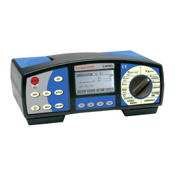
MI 2086 Eurotest Instrument description 2. Instrument description 2.1. Front panel Fig. 1. Front panel... - Page 9 MI 2086 Eurotest Instrument description Legend: ON/OFF key, to switch ON or OFF the instrument. Auto OFF will occur automatically 10 minutes after last strike to any key or function switch rotation. HELP key, to display help menu (connection of test leads and other data). Light key, to turn ON or OFF display backlight.
-
Page 10: Connector Panel
Instrument description 2.2 Connector panel Fig. 2. Connector panel Legend: Main test connector Protective connector cover (protects simultaneous connection of test and RS232 cable) Clamp/Probe (C2/P) test terminal Clamp (C1) test terminal RS 232 connector (to connect Eurotest 61557 to PC) -
Page 11: Bottom Side
MI 2086 Eurotest Instrument description 2.3. Bottom side Fig. 3. Bottom side Legend: Nylon strip (it serves the operator to carry the instrument hung on his neck). Auxiliary nylon strip (it serves the operator to fix the instrument along his body). Plastic cover (it fixes nylon strip to the instrument). -
Page 12: Standard Accessories
MI 2086 Eurotest Instrument description 2.4. Standard accessories See attached sheet, to compare received set of accessories with listed one. 2.5. Optional accessories See attached sheet, to check the list of possible optional accessories, which may be supplied upon request. 2.6. -
Page 13: Accessories Required For Specific Measurement
MI 2086 Eurotest Instrument description 2.7. Accessories required for specific measurement The table below presents accessories (standard or optional) required for specific measurement. The accessories marked as optional may also be standard ones in some set configurations; Please see attached list of standard accessories for your set configuration or contact your dealer for further information. -
Page 14: Measurement Instructions
How to carry out the measurement? Step 1 ♦ Connect test cable (Universal test cable or Tip commander) to Eurotest 61557. ♦ Set function switch to R position, the following menu will be displayed: 50 V .....Latest set nominal test voltage. - Page 15 MI 2086 Eurotest Measurement instructions Step 2 ♦ Select Test voltage by using the Uiso (F2) key. The voltage can be set to 50, 100, 250, 500 or 1000 V and it is currently displayed on top display line. Step 3 ♦...
- Page 16 MI 2086 Eurotest Measurement instructions switched off closed mains voltage switches Fig. 6. Connection of Universal Test Cable and optional Tip Commander (Order No. A 1002) Step 5 ♦ Press the START key and keep it pressed, until result is stabilised, then release the key.
-
Page 17: Varistor Over-Voltage Protection Devices
Measurements on electric installations in practice and theory. How to carry out the Breakdown voltage test? Step 1 ♦ Connect Universal test cable to Eurotest 61557. Note! Set function switch to Riso position and press the FUNC (F1), the following menu will be displayed. - Page 18 MI 2086 Eurotest Measurement instructions How to set the Low limit value? ♦ Press the Llim (F2) key, to enter Limit value adjustment mode, the following menu will be displayed: Fig. 9. Limit adjustment menu ♦ Value between 0 and 1000 V in steps of 5 V may be selected by using the ↑ (F2) and ↓...
- Page 19 MI 2086 Eurotest Measurement instructions Fig. 10. Connection of tested device Step 5 ♦ Press the START key and release it. Test voltage starts to rise (500 V/s) and as soon as varistor’s forward current reaches the value of 1 mA (breakdown voltage is defined at that current), test voltage will be displayed.
-
Page 20: Continuity Of Protective Conductors
Make sure, tested object to be deenergised (mains voltage disconnected) before starting the measurement! How to carry out the measurement? Step 1 ♦ Connect test cable (Universal test cable or Tip commander) to Eurotest 61557. ♦ ±200mA Set function switch to R / CONTINUITY position, “Continuity of protective conductors”... - Page 21 MI 2086 Eurotest Measurement instructions Step 3 ♦ Set High limit resistance value. Later will test results be compared with the set limit value and, if higher, they will be equipped with “!” mark and Result over limit message, while, if lower, they will be accompanied with sound signal (in case of active buzzer only).
- Page 22 MI 2086 Eurotest Measurement instructions ♦ Press the Comp (F4) key and release it, Compensating t. leads message will appear for a while, then displayed result will alter to 0,00 Ω and Co mark will appear on top display line, indicating the compensation was successfully accomplished.
- Page 23 MI 2086 Eurotest Measurement instructions Step 6 ♦ Press the START key and release it. Measurement will be carried out and result displayed afterwards. Each measurement is accomplished in two steps (polarity is reversed between the two steps automatically). See an example of displayed test result on figure below.
-
Page 24: Continuity
(see the chapter 5.2. Fuses). How to carry out the measurement? Step 1 ♦ Connect test cable (Universal test cable or Tip commander) to Eurotest 61557. ♦ ±200mA Set function switch to R / CONTINUITY position, “Continuity of protective conductors”... - Page 25 MI 2086 Eurotest Measurement instructions How to set the high limit value? ♦ Press the Hlim (F2) key, to enter “Limit value adjustment menu”; see the figure below: Fig. 19. Limit adjustment menu ♦ Value between 0,1 Ω and 20,0 Ω in steps of 0,1Ω may be set by using the ↑ (F2) and ↓...
- Page 26 MI 2086 Eurotest Measurement instructions 3 ph. M Option A 1002 Fig. 21. Connection of optional Tip Commander (Order No. A 1002) ♦ Press the START key again, to stop the measurement. Last current result will be displayed; see an example of displayed test result on figure below..Displayed result is equiped with buzzer sign in case, if it is lower than set high...
-
Page 27: Earth Resistance (Internal Generator)
Measurement instructions 3.5. Earth Resistance (internal generator) The Eurotest 61557 test instrument is able to carry out Earth Resistance measurement using tree different methods. The appropriate one is to be selected by the operator on basis of concrete earthing system to be tested. - Page 28 MI 2086 Eurotest Measurement instructions Range / discrete Step (Ω) value (Ω) 1 – 100 166, 250, 500, ⁄ 833, 1666, 2500, 5000 Fig. 24. Limit adjustment menu and table of presettable limit values ♦ Value between 1 Ω and 5000 Ω, according to the table above may be selected by using the ↑...
- Page 29 MI 2086 Eurotest Measurement instructions Option S 2002 MPEC >5d Fig. 26. Connection of optional Earth Test Set – 50 m (Order No. S 2002) Step 4 ♦ Press the START key and keep it pressed, until result is stabilised, then release the key.
- Page 30 MI 2086 Eurotest Measurement instructions How to carry out Earth Resistance measurement using standard four-lead test method in combination with test clamp? Step 1 ♦ Set function switch to ρ R position, “Earth Resistance” or “Earth Resistivity” menu will be displayed. ♦...
- Page 31 MI 2086 Eurotest Measurement instructions ... Make sure to connect test clamp under the E test terminal, otherwise parallel resistance of all other electrodes (R 1 up to R 3) will be measured! Step 4 ♦ Press the START key and keep it pressed, until result is stabilised, then release the key.
- Page 32 MI 2086 Eurotest Measurement instructions How to carry out Earth Resistance measurement using two test clamps? Step 1 ♦ Set function switch to ρ R position, “Earth Resistance” or “Earth Resistivity” menu will be displayed. ♦ Select Earth Resistance function using two test clamps by using the FUNC (F1) key.
- Page 33 MI 2086 Eurotest Measurement instructions Step 4 ♦ Press the START key and release it. The measurement starts to run (continuous measurement). Test results are currently displayed. ♦ Press the START key again after finishing the measurement, last result will stay displayed;...
-
Page 34: Specific Earth Resistance
MI 2086 Eurotest Measurement instructions 3.6. Specific Earth Resistance It is advisable to measure Earth Resistivity, when calculating parameters of earthing system (required length and surface of earth electrodes, most appropriate depth of installing earthing system etc.) in order to reach more accurate calculations. For additional general information concerning Earth Resistivity measurement, refer to enclosed handbook Measurements on electric installations in practice and theory. - Page 35 MI 2086 Eurotest Measurement instructions Set distance value Fig. 35. Distance value adjustment menu ♦ Value between 1m and 30 m in steps of 1 m may be selected by using the DIST (F2) key. The value is currently displayed on top display line. ♦...
- Page 36 MI 2086 Eurotest Measurement instructions Fig. 37. Example of Earth Resistivity test result ♦ Store displayed result for documentation purpose; see instructions how to store it in chapter 4.3. Storing test results. Notes! ♦ In case of present voltage higher than 20 V a.c./d.c. between H and E test terminals, the Earth Resistivity measurement will not be carried out after pressing START key, but the voltage will be displayed, equipped with “!”...
-
Page 37: Pe Terminal Test
3.7. PE terminal test While carrying out measurements, which require presence of mains voltage (R LOOP or RCD parameters), the Eurotest 61557 automatically tests presence of LOOP phase voltage on PE protection terminal. The test is actual to be done on all mains outlets (one-phase as well as three-phase) on new or adapted installations, where phase and protective conductors might be reversed by mistake. - Page 38 MI 2086 Eurotest Measurement instructions Fig. 39. Connection of Universal Test Cable to load connection terminals with reversed L and PE conductors Step 3 ♦ Touch PE test probe (operator touches it automatically, when pressing the START key, in order to carry out a measurement). If PE terminal is connected to phase voltage, warning message Dangerous PE voltage will appear on display, continuous bip bip….
-
Page 39: Rcd - Contact Voltage And Earth / Fault Loop Resistance
How to carry out the Contact Voltage measurement? Step 1 ♦ Connect test cable (Plug commander or Universal test cable) to Eurotest 61557. ♦ Set function switch to RCD position, one of RCD initial menus will be displayed. ♦... - Page 40 MI 2086 Eurotest Measurement instructions Step 4 ♦ Select Type of involved RCD by using the TYPE (F3) key. The following types can be selected: General, Selective, General Selective AC or A AC or A pulsed, A pulsed, A Selection is displayed on the top line. Step 5 ♦...
- Page 41 Contact Voltage function) the following procedure is advised to be carried out: Step 1 ♦ Connect test cable (Plug commander or Universal test cable) to Eurotest 61557. ♦ Set function switch to RCD position, one of RCD initial menus will be displayed.
- Page 42 Disconnect such appliances before measurement! ♦ Valid for GB version of the Eurotest 61557: If N/L2 and L/L1 test leads are connected reversed way (Universal test cable) or terminals on tested wall plug are reversed, L-N crossed message marked with “!” symbol will be displayed and no measurement will be carried out after pressing the START key.
-
Page 43: Rcd - Trip-Out Time
MI 2086 Eurotest Measurement instructions 3.9. RCD – Trip-Out Time In order to assure safe conditions, RCD device must trip out within a certain time, in case of present fault on connected electric appliance. See allowed trip out time ranges in the following table. - Page 44 MI 2086 Eurotest Measurement instructions Step 3 ♦ Δ Δ Select Nominal differential current I n by using the I n (F2) key. The current can be set to 10, 30, 100, 300, 500 or 1000* mA and it is currently displayed on top display line.
- Page 45 MI 2086 Eurotest Measurement instructions Fig. 48. Example of Trip out time test result ♦ Store displayed result for documentation purpose; see instructions how to store it in chapter 4.3. Storing test results. Test of Selective RCD For safety reason, Contact voltage measurement is carried out (regardless of RCD type) before Trip out Time measurement is realised.
-
Page 46: Rcd - Trip-Out Current
MI 2086 Eurotest Measurement instructions 3.10. RCD – Trip-Out Current For general information concerning Tripping current measurement, refer to enclosed handbook Measurements on electric installations in practice and theory. How to carry out the measurement? Step 1 ♦ Follow Step 1, described under paragraph 3.7. Contact Voltage, except selecting RCD function;... - Page 47 MI 2086 Eurotest Measurement instructions Step 5 ♦ Connect test cable to tested object. Follow Step 5 described under paragraph 3.7. Contact Voltage. Step 6 ♦ Press the START key and release it. Wait for the measurement to be accomplished (stepping up current is displayed during measurement), final result will be displayed afterwards.
-
Page 48: Rcd - Automatic Test
MI 2086 Eurotest Measurement instructions 3.11. RCD – Automatic Test Purpose of the function is to carry out complete test of RCD and measurement of belonging parameters (Contact Voltage, Earth / Fault loop resistance and Trip out time at different fault currents) in one set of automatic tests, led by the instrument. If any false parameter is noticed during this automatic test, individual parameter test is to be used for further investigation. - Page 49 MI 2086 Eurotest Measurement instructions Step 7 ♦ Press the START key and release it. Measurement will start to run, partial tests will be followed by partial results as follows: The next presentation is valid for standard type of RCD. test Δ...
- Page 50 MI 2086 Eurotest Measurement instructions Fig. 54. Example of the third partial result Reswitch RCD, fourth test will follow automatically. test Δ Trip out time test, using test current Itest = I n, at negative start polarity of test current (180°).
- Page 51 MI 2086 Eurotest Measurement instructions RCD O.K. mark indicates that all partial results are within Limit values. Δ Uc ..Contact voltage at I Δ (standard RCD) or at 2I (selective type). Fig. 57. Example of the sixth partial result ♦...
-
Page 52: Fault Loop Impedance And Prospective Short-Circuit Current
Measurements on electric installations in practice and theory. How to carry out the measurement? Step 1 ♦ Connect test cable (Plug commander or Universal test cable) to Eurotest 61557. ♦ Set function switch to Z position, the following menu will be displayed: LOOP Isc.. - Page 53 MI 2086 Eurotest Measurement instructions Option A 1001 Fig. 59. Connection of optional Plug Commander (Order No. A 1001) Fig. 60. Connection of Universal Test Cable Step 4 ♦ Press the START key and release it. Measurement will be carried out and result displayed afterwards.
- Page 54 MI 2086 Eurotest Measurement instructions ♦ Store displayed result for documentation purpose; see instructions how to store it in chapter 4.3. Storing test results. Notes! ♦ Nominal input voltage range is 100 ÷ 264 V, if voltage is out of the range, “!” mark and Voltage Ulpe <...
-
Page 55: Contact Voltage At Prospective Short-Circuit Current
58. Step 1 ♦ Connect Universal test cable to main test connector and auxiliary test lead to C2/P test terminal of the Eurotest 61557. ♦ Set function switch to Z position, the menu according to the figure 54. will LOOP be displayed. - Page 56 Measurement instructions Step 4 ♦ Press the START key and release it. The Eurotest 61557 will automatically recognise connection of auxiliary test probe, measurement will be carried out and result displayed afterwards. See an example of the result on the figure below.
-
Page 57: Line Impedance And Prospective Short-Circuit Current
Measurements on electric installations in practice and theory. How to carry out the measurement? Step 1 ♦ Connect test cable (Plug commander or Universal test cable) to Eurotest 61557. ♦ Set function switch to Z position, the following menu will be displayed: LINE Isc ... - Page 58 MI 2086 Eurotest Measurement instructions Fig. 66. Connection of Universal Test Cable Step 3 ♦ Press the START key and release it. Measurement will be carried out and result displayed afterwards. See an example of the result on the figure below. Ipsc (Isc marked on display) = = Un ⋅1,06 / Z LINE...
-
Page 59: N-Pe Loop Resistance And Prospective Short-Circuit Current
Measurements on electric installations in practice and theory. How to carry out the measurement? Step 1 ♦ Connect test cable (Plug commander or Universal test cable) to Eurotest 61557. ♦ Set function switch to R position, the following menu will be displayed: LOOP N-PE Isc ..Prospective short-circuit... - Page 60 MI 2086 Eurotest Measurement instructions Fig. 70. Connection of Universal Test Cable Step 3 ♦ Press the START key and release it, the measurement will be carried out and result displayed afterwards; see an example of the result on the figure below. Ipsc (Isc marked on display) = = Un ⋅1,06 / R LOOP N-PE...
-
Page 61: Phase Rotation
MI 2086 Eurotest Measurement instructions 3.16. Phase rotation For general information concerning the test, refer to enclosed handbook Measurements on electric installations in practice and theory. How to carry out the measurement? Step 1 ♦ Connect test cable (Three phase cable or Universal test cable) to Eurotest 61557. - Page 62 MI 2086 Eurotest Measurement instructions Step 3 ♦ Press the START key and release it. Measurement starts to run (continuous measurement), result is currently displayed; see an example of the result on the figure below. 1.2.3 Phase rotation at tested object is in accordance with test leads' marks (figure 67.
-
Page 63: Current
Measurements on electric installations in practice and theory. How to carry out the measurement? Step 1 ♦ Connect 1A/1mA test clamp (green one) to Eurotest 61557; see the figure 72. ♦ Set function switch to CURRENT clamp position, “Current” or “Peak current” menu will be displayed. - Page 64 4.3. Storing test results. Note! ♦ Use test clamp supplied by Metrel or other with similar characteristics (Current/Current, 1000:1, appropriate measurement range, consider error of test clamp at final result)! How to carry out the measurement of Maximal peak current...
- Page 65 Store displayed result for documentation purpose; see instructions how to store it in chapter 4.3. Storing test results. Note! ♦ Use test clamp supplied by Metrel or other with similar characteristics (Current/Current, 1000:1, appropriate measurement range, consider error of test clamp at final result)!
-
Page 66: Illumination
3.18. Illumination How to carry out the illumination measurement? Step 1 ♦ Connect LUXmeter probe to Eurotest 61557. ♦ Set function switch to SENSOR position, the following menu will be displayed. 18 : 35 : 27 Fig. 81. Illumination measurement initial menu Step 2 ♦... - Page 67 MI 2086 Eurotest Measurement instructions Step 3 ♦ Turn on the LUXmeter probe pressing ON/OFF key. Green lamp should light. Position LUXmeter probe parallel to the surface to be evaluated (press the HELP key for basic connection information). Fig. 83. LUXmeter probe positioning Step 4 Press the START key and release it.
-
Page 68: Tracing Of Electric Installation
MI 2086 Eurotest Measurement instructions 3.19. Tracing of electric installation There are two possible manners to trace installation by using the Eurotest 61557 namely: ♦ Eurotest 61557 loads installation under mains voltage in a pulsed manner. In that case, hand-held indicator follows electro-magnetic field, generated around the loaded conductor. - Page 69 ♦ Press the START key and release it. Signal generating starts to run (continuous function). The Eurotest 61557 will recognise automatically, whether there is a free-voltage or energised installation. On that basis will instrument start to impose it’s own signal (free-voltage installation) or to load mains voltage (mains...
- Page 70 MI 2086 Eurotest Measurement instructions Fig. 88. Display menu, while tracing function is running - installation under mains voltage (left figure) and voltage-free installation (right figure) Step 4 ♦ Set the same test signal-receiving mode on hand-held indicator, as written on display of the instrument (see the figure above).
-
Page 71: Power
Measurements on electric installations in practice and theory. How to carry out the measurement? Step 1 ♦ Connect 1A/1mA test clamp and Universal test cable to Eurotest 61557; see the figure 90. ♦ Set function switch to POWER/ENERGY position, “Power” or “Energy” menu will be displayed. - Page 72 MI 2086 Eurotest Measurement instructions Step 3 ♦ Press the START key and release it. Measurement starts to run (continuous measurement), result is currently displayed. ♦ Press the START key again after finishing the measurement, last current result will stay displayed; see an example of the result on figure below. Fig.
-
Page 73: Energy
MI 2086 Eurotest Measurement instructions 3.21. Energy For general information concerning the measurement, refer to enclosed handbook Measurements on electric installations in practice and theory. How to carry out the measurement? Step 1 ♦ Follow Step 1, described under the paragraph 3. 19. Power, except selecting measurement function;... - Page 74 MI 2086 Eurotest Measurement instructions Fig. 93. Example of final energy result ♦ Store displayed result for documentation purpose; see instructions how to store it in chapter 4.3. Storing test results. Notes! ♦ Take care, to connect voltage test tips and current clamp correctly (polarity and direction of test clamp –...
-
Page 75: Harmonics
How to carry out the measurement? Step 1 ♦ Connect 1A/1mA test clamp to Eurotest 61557; see the figure 91. (only if current harmonics are to be measured). ♦ Connect appropriate test cable (Universal test cable or Plug commander) to Eurotest 61557;... - Page 76 MI 2086 Eurotest Measurement instructions Fig. 95. Connection of optional Low-range Current Clamp (Order No. A 1018) in combination with Universal Test Cable or opt. Tip Commander (Order No. A 1002) Step 3 ♦ Press the START key and release it. Measurement starts to run (continuous measurement), result is currently displayed.
- Page 77 MI 2086 Eurotest Measurement instructions Fig. 98. Example of displayed result (individual harmonics from 13-th up to 21-th component) ♦ Press the START key again, to stop the measurement. Last current result will stay displayed. ♦ Store displayed result for documentation purpose; see instructions how to store it in chapter 4.3.
-
Page 78: Other Operations
MI 2086 Eurotest Other operations 4. Other operations 4.1. Set-up functions The following actions can be done in the Set-up menu: ♦ Display contrast adjustment (within 0 and 100 %) ♦ Real time & Date setting ♦ Communication parameter – Baud rate selection (2400, 4800, 9600 or 19200) ♦... -
Page 79: Creating Installation Structure On Pc
The organisation is called Installation structure and may be created by a measurer either directly on the Eurotest 61557 simultaneously with storing test results, or prepared in advance by means of PC with installed PC SW Euro Link. - Page 80 MI 2086 Eurotest Other operations How to create Installation structure on PC Step 1 Install enclosed PC SW Euro Link – Lite to your PC (printing out final protocols and test reports is possible using the Euro Link – Pro version only). Step 2 Create the Installation structure on basis of actual installation plan (use HELP menu).
-
Page 81: Storing Test Results
Table 2. List of the measurements, that can be attached to a certain meas. place Step 3 Connect the Eurotest 61557 to PC via enclosed RS 232 cable and transfer created structure to the Eurotest 61557. Now the Eurotest 61557 is ready for carrying out measurements and storing test results into prepared installation structure. - Page 82 If no structure has been transferred to Eurotest 61557 from PC, then appropriate one can be created using the add key. The Eurotest 61557 will offer only standard names in this case, which cannot be renamed through instrument's keyboard. This can be done later on PC after transferring stored results back to PC again for final protocol purpose.
-
Page 83: Recalling Stored Test Results
Already started storing procedure can be interrupted pressing the ESC key. ♦ Installation structure once installed to the Eurotest 61557 (either by PC or through instrument's keyboard) cannot be erased any longer, except when performing erasing of all stored results in SETUP menu. Only basic structure (installed by the producer of test instrument;... -
Page 84: Erasing Stored Test Results
MI 2086 Eurotest Other operations Fig. 103. Example of recalled last stored test result Step 4 ♦ Use the ↑ (F1) and ↓ (F2) keys to recall other results stored under the same measurement place. Notes! ♦ All potential subresults and function parameters will be recalled too. ♦... - Page 85 ♦ Installation structure installed to the Eurotest 61557 (either by PC or through instrument's keyboard) will be erased together with results too. Only basic structure (installed by the producer of test instrument; see the figure 96) will stay installed.
-
Page 86: Reset Of The Instrument
Other operations 4.6. Reset of the instrument If any malfunction is noticed when dealing with the Eurotest 61557, RESET function is advised to be effected. In that case all settable parameters will be set to their initial values; see the table below. Stored results will not be erased. -
Page 87: Maintenance
MI 2086 Eurotest Maintenance 5. Maintenance 5.1. Batteries - Disconnect test cable and switch off the instrument, before removing battery compartment cover! - Hazardous voltage under the battery compartment cover! Battery condition is currently displayed; see the battery condition mark in the right upper corner of display. -
Page 88: Fuses
MI 2086 Eurotest Maintenance One set of full-capacity batteries can supply the instrument approx. 50 hours at the ratio measurement / pause = 5s / 25s Commander and Locator batteries: Red lamp ON means low battery condition. Unscrew two screws on backside of the device in order to remove battery cover. -
Page 89: Cleaning
Tel.: +386 1 75 58 200 Fax.: +386 1 75 49 226 E-mail: metrel@metrel.si http://www.metrel.si Unauthorised person is not allowed to open the Eurotest 61557. There are no user replaceable components inside the instrument, except three fuses, refer to paragraph 5.2. Fuses. -
Page 90: Technical Specification
MI 2086 Eurotest Technical specification 6. Technical specification 6.1. Functions Insulation resistance Continuity Meas. range Riso (Un ≥ 250V) .. (0.008 ÷ 1000)MΩ Display range Resolution Accuracy Display range Resolution Accuracy* R (Ω) (Ω) 0.0 ÷ 199.9 ±(3% of r. + 3D) Riso (MΩ) (MΩ) Un ≥... - Page 91 MI 2086 Eurotest Technical specification Indication in case of low clamp current ..< 0.5 mA Specific Earth Resistance Automatic test of noise current ......yes (resistivity) Additional clamp error is to be considered. All technical data listed under four-lead method are valid, except display range table;...
- Page 92 MI 2086 Eurotest Technical specification ΔN Calculation ........R ) = Uc / I Fault Loop Impedance Measurement principle..with auxiliary probe (R and Prospective Short-circuit without auxiliary probe (R Current ΔN Test current ..........< 0.5 I , R, Xl ....(0.11 ÷ 1999)Ω Meas.
- Page 93 MI 2086 Eurotest Technical specification Display range Resolution Accuracy Current (True RMS) Ipsc (A) 0.06 ÷ 19.99 0.01 Display range Resolution Accuracy 20.0 ÷ 199.9 Consider acc. I (A) of Z 200 ÷ 1999 L-N(L) 0.0m ÷ 99.9m ±(5% of r. + 3D) 0.1m 2.00k ÷...
- Page 94 MI 2086 Eurotest Technical specification Illumination (LUX meter type C) Energy Display range Resolution Accuracy Display range Resolution Accuracy E (Lux) (Lux) W (Wh) (Wh) 0.0 ÷ 19.99 0.000 ÷ 1.999 0.01 0.001 20.0 ÷ 199.9 ±(10 % of r. + 2.00 ÷...
-
Page 95: General Characteristics
MI 2086 Eurotest Technical specification 6.2. General characteristics Power supply..6Vd.c. (4 × 1.5V battery IEC LR14) Protection classification....double insulation Automatic comparation of test result with set high Over-voltage cat. . . CATIII / 300 V or CAT II /600 V and low limit value..........
Need help?
Do you have a question about the Eurotest 61557 and is the answer not in the manual?
Questions and answers