Vega VEGAPULS 68 Operating Instructions Manual
4 ... 20 ma/hart - four-wire
Hide thumbs
Also See for VEGAPULS 68:
- Operating instructions manual (105 pages) ,
- Quick setup manual (24 pages) ,
- Product information (20 pages)

Related Manuals for Vega VEGAPULS 68


Summary of Contents for Vega VEGAPULS 68
-
Page 1: Operating Instructions
Operating Instructions VEGAPULS 68 4 … 20 mA/HART - four-wire Document ID: 29262... -
Page 2: Table Of Contents
Parameter adjustment with PACTware ................49 7.3 Parameter adjustment with AMS™ and PDM ..............50 Saving the parameter adjustment data ................51 8 Maintenance and fault rectification 8.1 Maintenance, cleaning ....................52 Rectify faults ........................52 Exchanging the electronics module ................53 VEGAPULS 68 • 4 … 20 mA/HART - four-wire... - Page 3 10.4 Trademark ........................73 Safety instructions for Ex areas Take note of the Ex specific safety instructions for Ex applications. These instructions are attached as documents to each instrument with Ex approval and are part of the operating instructions manual. Editing status: 2016-07-07 VEGAPULS 68 • 4 … 20 mA/HART - four-wire...
-
Page 4: About This Document
This arrow indicates a single action. Sequence of actions Numbers set in front indicate successive steps in a procedure. Battery disposal This symbol indicates special information about the disposal of bat- teries and accumulators. VEGAPULS 68 • 4 … 20 mA/HART - four-wire... -
Page 5: For Your Safety
During work on and with the device the required personal protective equipment must always be worn. Appropriate use VEGAPULS 68 is a sensor for continuous level measurement. You can find detailed information about the area of application in chapter "Product description". Operational reliability is ensured only if the instrument is properly used according to the specifications in the operating instructions manual as well as possible supplementary instructions. -
Page 6: Ce Conformity
FCC ID: O6QPULS68 • IC: 3892A-PS68 Modifications not expressly approved by VEGA will lead to expiry of the operating licence according to FCC. VEGAPULS 68 is in conformity with part 15 of the FCC regulations. Take note of the respective operating regulations: • This device may not cause interference, and •... - Page 7 2 For your safety Please help us fulfil this obligation by observing the environmental instructions in this manual: • Chapter "Packaging, transport and storage" • Chapter "Disposal" VEGAPULS 68 • 4 … 20 mA/HART - four-wire...
-
Page 8: Product Description
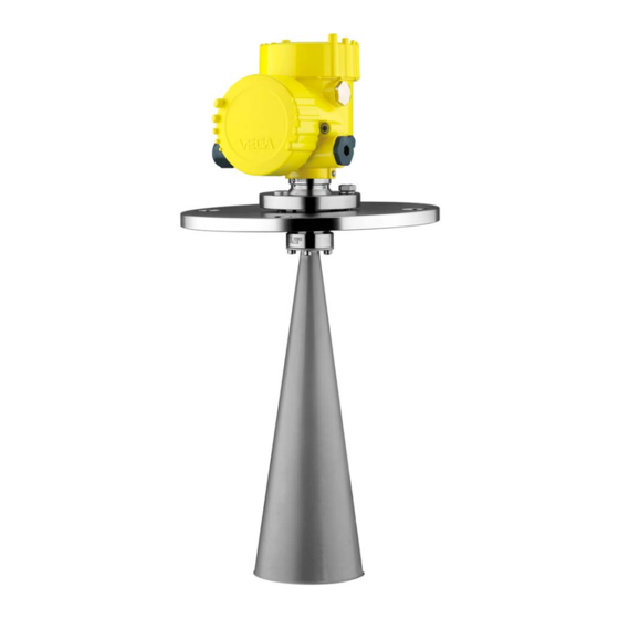
The VEGAPULS 68 consists of the components: • Horn or parabolic antenna • process fitting (depending on the version flange or thread) • Bulk solid • Each optionally available with swivelling holder (only with flange), rinsing air connection, reflux valve • Housing with electronics • Housing cover, optionally available with display and adjustment module PLICSCOM The components are available in different versions. VEGAPULS 68 • 4 … 20 mA/HART - four-wire... - Page 9 3 Product description Fig. 1: VEGAPULS 68 - horn antenna and swivelling holder Housing cover with integrated PLICSCOM (optional) Housing with electronics 3 Swivelling holder with flange Horn antenna Type label The type label contains the most important data for identification and use of the instrument: • Instrument type • Article and serial number device •...
-
Page 10: Principle Of Operation
Application area VEGAPULS 68 is a radar sensor in K-band technology for continuous level measurement of solids. A version of VEGAPULS 68 is available for each area of application. • The version with horn antenna is particularly suitable for measure- ment of virtually all bulk solids in small silos and vessels. -
Page 11: Accessories And Replacement Parts
You can find further information in the operating instructions "Interface adapter VEGACONNECT" (Document-ID 32628). VEGADIS 81 The VEGADIS 81 is an external display and adjustment unit for VEGA plics sensors. ® For sensors with double chamber housing the interface adapter "DISADAPT"... - Page 12 You find further information in the mounting instructions "Antenna impedance cone VEGAPULS 62 and 68" (Document-ID 31381). Antenna covers The antenna covers can be retrofitted to the VEGAPULS 68 radar sensors. They prevent from dust accumulating on the antenna system. You find further information in the mounting instructions "Antenna cov- ers VEGAPULS 68" (Document-ID 33543). VEGAPULS 68 • 4 … 20 mA/HART - four-wire...
-
Page 13: Mounting
Prior to setup you have to replace these protective caps with ap- proved cable glands or close the openings with suitable blind plugs. Measuring range The reference plane for the measuring range of the sensors is the lower edge of the flange or the seal surface of the thread. VEGAPULS 68 • 4 … 20 mA/HART - four-wire... - Page 14 If the medium reaches the antenna, buildup can form on it and cause faulty measurements later on. Polarisation The emitted radar pulses of VEGAPULS 68 are electromagnetic waves. They thus have electrical and magnetical components that are perpendicular to each other. The polariation is defined by the direction of the electrical component. With radar sensors, the polarisation can be used to considerably reduce the effect of false echoes by turning the instrument in the connection flange or mounting boss. The posi-...
-
Page 15: Mounting Preparations - Horn Antenna
You can find the specifications in chapter "Technical data" and on the nameplate. Mounting preparations - Horn antenna VEGAPULS 68 is also available in versions where the antenna has a bigger diameter than the process fitting (thread, flange). The antenna must therefore be disconnected from the process fitting before mount- ing. Proceed as follows: 1. Loosen the hexagon socket screws (3) on the antenna socket with an Allen wrench (size 3) 2. -
Page 16: Mounting Preparations - Parabolic Antenna
9. Tighten compression nut (1) with SW 41, torque max. 50 Nm 10. Tighten counter nut (2) with SW 36, torque max. 40 Nm. Note: Take note for VEGAPULS 68 with rinsing air connection that the holes in the antenna and in the process fitting correspond. This ensures a sufficient air flow (the air is led through the holes to the feed system. A rinsing of the parabolic antenna in total is not intended). -
Page 17: Mounting Instructions
4 Mounting Mounting instructions Horn and parabolic The illustrations with the following mounting instructions show a antenna VEGAPULS 68 with horn antenna. The mounting instructions apply analogously also to the version with parabolic antenna. Installation position Mount the sensor at least 200 mm (7.874 in) away from the vessel wall. > 200 mm (7.87") - Page 18 If mounting in the centre of the silo is not possible, the sensor can be directed to the vessel center by using the optional swivelling holder. The following description shows a simple way to determine the required angle of inclination. VEGAPULS 68 • 4 … 20 mA/HART - four-wire...
- Page 19 4 Mounting Fig. 9: Proposal for installation after orientation VEGAPULS 68 The angle of inclination depends on the vessel dimensions. It can be easily checked with a suitable level or water leve on the sensor. Tip: VEGA recommends the adjusting aid from VEGA line of accessory.
- Page 20 3. Tighten the terminal screw, torque max. 15 Nm. Information: The hexagon screws must not be loosened. Inflowing medium Mounting should not be too close to the inflowing material as the microwave signal will be interferred. The optimum mounting position is on the opposite of the filling. To avoid strong pollution, the distance to the filter or dust extraction must be as big as possible. VEGAPULS 68 • 4 … 20 mA/HART - four-wire...
- Page 21 10 mm (0.4 in) out of the socket. Fig. 11: Recommended socket mounting If the reflective properties of the medium are good, you can mount VEGAPULS 68 on sockets which are higher than the length of the antenna. You will find recommended values for socket heights in the following illustration. The socket end should be smooth and burr-free, if possible also rounded.
- Page 22 The optimal mounting position is on the outer wall of the silo with the sensor directed towards the emptying aperture in the silo center. Fig. 13: Mounting of VEGAPULS 68 in multiple chamber silos VEGAPULS 68 • 4 … 20 mA/HART - four-wire...
- Page 23 4 Mounting Fig. 14: Orientation of VEGAPULS 68 for emptying in the silo center Vessel installations Silo installations such as e.g. ladders, level switches, struts, and also structured vessel walls, can cause false echoes that get superim- posed on the useful echo. The mounting location of the radar sensor should be a place where no installations cross the microwave signals.
- Page 24 4 Mounting Tip: In case of extreme dust in the antenna system, VEGAPULS 68 is available with rinsing connection e.g. for air. The air is distributed via channels in the antenna system and keeps it virtually free of dust. Fig. 16: Purging air connection with horn antenna Fig.
- Page 25 Fig. 18: Radar sensors on traverse crane Information: Keep in mind that for these applications, the sensors are designed for relatively slow level changes. When using VEGAPULS 68 on a mov- able bracket, the max. measuring rate must be observed (see chapter "Technical data").
-
Page 26: Connecting To Power Supply
In Ex systems, the grounding is carried out according to the installa- tion regulations. With the Exd version, the minus side of the signal output is galvani- cally connected to ground via protective diodes. When connecting the instrument to a grounded PLC, equalising currents can flow in case VEGAPULS 68 • 4 … 20 mA/HART - four-wire... -
Page 27: Connection Procedure
11. Connect the lead cable for power supply in the same way accord- ing to the wiring plan, in addition connect the ground conductor to the inner ground terminal. 12. Screw the housing lid back on The electrical connection is finished. VEGAPULS 68 • 4 … 20 mA/HART - four-wire... -
Page 28: Wiring Plan, Double Chamber Housing
Fig. 20: Double chamber housing Housing cover, connection compartment Blind plug or plug M12 x 1 for VEGADIS 61 (optional) Housing cover, electronics compartment Filter element for air pressure compensation Cable gland VEGAPULS 68 • 4 … 20 mA/HART - four-wire... - Page 29 Ground terminal for connection of the ground conductor and screen Spring-loaded terminals for voltage supply Information: Keep in mind that the display and adjustment module must only be used in the electronics compartment. VEGAPULS 68 • 4 … 20 mA/HART - four-wire...
-
Page 30: Switch-On Phase
Fig. 23: Wiring plan, double chamber housing Voltage supply Signal output Switch-on phase Switch-on phase After connecting VEGAPULS 68 to power supply or after a voltage recurrence, the instrument carries out a self-check for approx. 30 seconds: • Internal check of the electronics •... -
Page 31: Set Up With The Display And Adjustment Module Plicscom
4. Screw housing lid with inspection window tightly back on Disassembly is carried out in reverse order. The display and adjustment module is powered by the sensor, an ad- ditional connection is not necessary. VEGAPULS 68 • 4 … 20 mA/HART - four-wire... -
Page 32: Adjustment System
Adjustment system Fig. 25: Display and adjustment elements LC display Indication of the menu item number Adjustment keys • [OK] key: Key functions VEGAPULS 68 • 4 … 20 mA/HART - four-wire... -
Page 33: Setup Steps
To perform the adjustment, enter the distance with full and empty ves- sel, see the following example: VEGAPULS 68 • 4 … 20 mA/HART - four-wire... - Page 34 3. Prepare the % value for editing with [OK] and set the cursor to the requested position with [->]. Set the requested percentage value with [+] and save with [OK]. The cursor jumps now to the distance value. VEGAPULS 68 • 4 … 20 mA/HART - four-wire...
- Page 35 To adapt the sensor to these measuring conditions, this menu item offers different options depending on whether liquid or solid is selected. With "Solid" these are "Silo" or "Bunker", with "Liq- uid", "Storage tank", "Stilling tube", "Open vessel" or "Stirred vessel". Vessel form Silo VEGAPULS 68 • 4 … 20 mA/HART - four-wire...
- Page 36 Enter the requested parameters via the appropriate keys, save your settings and jump to the next menu item with the [->] key. Caution: Note the following if the VEGAPULS 68 with corresponding approval is used as part of an overfill protection system according to WHG (Water Resources Act): If a linearisation curve is selected, the measuring signal is no longer necessarily linear to the filling height. This must be considered by the...
- Page 37 100 % = 100.0 l Display - Backlight A background lighting integrated by default can be adjusted via the adjustment menu. The function depends on the height of the supply voltage. See "Technical data/Voltage supply". VEGAPULS 68 • 4 … 20 mA/HART - four-wire...
- Page 38 The selected curve is updated continuously. With the [OK] key, a submenu with zoom functions is opened. The following functions are available with "Echo and false echo curve": VEGAPULS 68 • 4 … 20 mA/HART - four-wire...
- Page 39 Check the distance to the product surface, because if an incorrect (too large) value is entered, the existing level will be saved as a false signal. The level would then no longer be detectable in this area. VEGAPULS 68 • 4 … 20 mA/HART - four-wire...
- Page 40 The menu item "Extended setting" offers the possibility to optimise Service - Extended set- ting VEGAPULS 68 for applications in which the level changes very quickly. To do this, select the function "Quick level change > 1 m/min.". Extended setting quick level change > 1 m/min.
- Page 41 Current output - max. current 20 mA Current output - min. current 4 mA Current output - failure < 3.6 mA Sensor-specific basic adjustment. Depending on the sensor type, see chapter "Technical data". VEGAPULS 68 • 4 … 20 mA/HART - four-wire...
- Page 42 SIL via the indicating and adjustment module. The SIL factory setting cannot be deactivated by the user. Special parameters are parameters which are set customer-specifically on the service level with the adjustment software PACTware. VEGAPULS 68 • 4 … 20 mA/HART - four-wire...
- Page 43 The following safety-relevant data are not read out or written: • HART mode • • The 4 … 20 mA signal of the HART sensor is switched off. The sensor consumes a constant current of 4 mA. The measuring signal is transmitted exclusively as digital HART signal. VEGAPULS 68 • 4 … 20 mA/HART - four-wire...
- Page 44 Date of last change using PC: Date of the last change of sensor parameters via PC Last change using PC • Sensor details, e.g. approval, process fitting, seal, measuring cell, measuring range, electronics, housing, cable entry, plug, cable length etc. VEGAPULS 68 • 4 … 20 mA/HART - four-wire...
-
Page 45: Menu Schematic
Sensor Display Basic adjustment ▶ Display Diagnostics Service Info Displayed value Display unit Scaling Backlight ▼ ▼ Scaled 0 % = 0.0 l Volume Switched off ▼ 100 % = 100.0 l VEGAPULS 68 • 4 … 20 mA/HART - four-wire... - Page 46 Basic adjustment Display Diagnostics Service ▶ Info Instrument type Date of manufacture Last change using PC Sensor characteristics 22. November 2010 Software version Display now? Serial number 3.80 22. November 2010 12345678 VEGAPULS 68 • 4 … 20 mA/HART - four-wire...
-
Page 47: Saving The Parameter Adjustment Data
They are thus available for multiple use or service purposes. If VEGAPULS 68 is equipped with a display and adjustment module, the most important data can be read out of the sensor into the display and adjustment module. -
Page 48: Set Up With Pactware And Other Adjustment Programs
Fig. 28: Connection via VEGACONNECT externally I²C bus (com.) interface on the sensor I²C connection cable of VEGACONNECT VEGACONNECT USB cable to the PC Necessary components: • VEGAPULS 68 • PC with PACTware and suitable VEGA DTM VEGAPULS 68 • 4 … 20 mA/HART - four-wire... -
Page 49: Parameter Adjustment With Pactware
Power supply unit or processing system Note: With power supply units with integrated HART resistance (internal resistance approx. 250 Ω), an additional external resistance is not necessary. This applies, e. g. to the VEGA instruments VEGATRENN 149A, VEGADIS 371, VEGAMET 381. Common Ex separators are also usually equipped with a sufficient current limitation resistance. In such cases, VEGACONNECT 4 can be connected parallel to the 4 …... -
Page 50: Parameter Adjustment With Ams™ And Pdm
Parameter adjustment with AMS™ and PDM For VEGA sensors, instrument descriptions for the adjustment programs AMS™ and PDM are available as DD or EDD. The instru- ment descriptions are already implemented in the current versions of AMS™ and PDM. For older versions of AMS™ and PDM, a free-of-charge download is available via Internet. Move to www.vega.com. VEGAPULS 68 • 4 … 20 mA/HART - four-wire... -
Page 51: Saving The Parameter Adjustment Data
It is recommended to document or save the parameter adjustment data. That way they are available for multiple use or service purposes. The VEGA DTM Collection and PACTware in the licensed, profession- al version provide suitable tools for systematic project documentation and storage. VEGAPULS 68 • 4 … 20 mA/HART - four-wire... -
Page 52: Maintenance And Fault Rectification
24 hour service hotline Should these measures not be successful, please call in urgent cases the VEGA service hotline under the phone no. +49 1805 858550. The hotline is manned 7 days a week round-the-clock. Since we offer this service worldwide, the support is only available in the English language. The service is free, only standard call charges are incurred. -
Page 53: Exchanging The Electronics Module
Or on site by the user In both cases, the sensor serial number is necessary. The serial num- bers are stated on the type label of the instrument, inside the housing or on the delivery note. VEGAPULS 68 • 4 … 20 mA/HART - four-wire... -
Page 54: Software Update
Attach the completed form and, if need be, also a safety data sheet outside on the packaging • Please contact the agency serving you to get the address for the return shipment. You can find the agency on our home page www.vega.com. VEGAPULS 68 • 4 … 20 mA/HART - four-wire... -
Page 55: Dismount
WEEE directive. Correct disposal avoids negative effects on humans and the environ- ment and ensures recycling of useful raw materials. Materials: see chapter "Technical data" If you have no way to dispose of the old instrument properly, please contact us concerning return and disposal. VEGAPULS 68 • 4 … 20 mA/HART - four-wire... -
Page 56: Supplement
Torques Max. torques, antenna system Ʋ Mounting screws, antenna cone 2.5 Nm (1.8 lbf ft) Ʋ Compression nut, parabolic antenna 50 Nm (36.89 lbf ft) Ʋ Counter nut, parabolic antenna 40 Nm (29.50 lbf ft) VEGAPULS 68 • 4 … 20 mA/HART - four-wire... - Page 57 Ʋ ø 40 mm (1.575 in) 22° Ʋ ø 48 mm (1.89 in) 18° Ʋ ø 75 mm (2.953 in) 10° With inductive load ohmic share min. 25 Ω/mH. Corresponds to the range with 50 % of the emitted power VEGAPULS 68 • 4 … 20 mA/HART - four-wire...
- Page 58 Time to output the correct level (with max. 10 % deviation) after a sudden level change. Incl. non-linearity, hysteresis and non-repeatability. Relating to the nominal measuring range, in the temperature range -40 … +80 °C . VEGAPULS 68 • 4 … 20 mA/HART - four-wire...
- Page 59 Ʋ Parabolic antenna mechanical vibrations with 1 g and 5 … 100 Hz Data on rinsing air connection Pressure < 6 bar (87.02 psi) Air quantity see diagram Tested according to the guidelines of German Lloyd, GL directive 2. VEGAPULS 68 • 4 … 20 mA/HART - four-wire...
- Page 60 – 1 x plug (depending on the version), 1 x blind plug M20 x 1.5; plug M12 x 1 for VEGADIS 61 (optional) Spring-loaded terminals for wire cross- < 2.5 mm² (AWG 14) section Display and adjustment module Voltage supply and data transmission through the sensor Indication LC display in dot matrix VEGAPULS 68 • 4 … 20 mA/HART - four-wire...
- Page 61 For that reason the associated approval documents of these instruments have to be carefully noted. They are part of the delivery or can be downloaded under www.vega.com, "VEGA Tools" and "Instrument search" as well as in the general download area.
-
Page 62: Dimensions
ø48 3" ø75 4" ø95 inch 3.94" ø1.58" 1½" 4.72" ø1.89" 2" 8.50" ø2.95" 3" 16.93" ø3.74" 4" Fig. 35: VEGAPULS 68, horn antenna in threaded version Standard with temperature adapter VEGAPULS 68 • 4 … 20 mA/HART - four-wire... - Page 63 1½" ø40 2" ø48 3" ø75 4" ø95 inch 3.94" ø1.58" 1½" 4.72" ø1.89" 2" 8.50" ø2.95" 3" 16.93" ø3.74" 4" Fig. 36: VEGAPULS 68, horn antenna in threaded version with purging air connection and reflux valve (option) Standard with temperature adapter Purging air connection G⅛ A for mounting of a suitable adapter Reflux valve - unmounted (with non-Ex optionally available, with Ex in the scope of delivery), for tube diam- eters 6 mm VEGAPULS 68 • 4 … 20 mA/HART - four-wire...
- Page 64 An antenna extension causes a reduction of sensitivity at close range in dependence on product properties. A suitable support for the antenna extension must be provided as required by its length. VEGAPULS 68 • 4 … 20 mA/HART - four-wire...
- Page 65 8xø19,1 4" 150 lb 9.00" 0.94" 7.50" 8xø0.75" 3.74" 16.93" 16.93" 6" 150 lb 279,4 25,4 241,3 8xø22,4 6" 150 lb 11.00" 1.00" 9.50" 8xø0.88" 3.74" Fig. 38: VEGAPULS 68, horn antenna in flange version Standard with temperature adapter VEGAPULS 68 • 4 … 20 mA/HART - four-wire...
- Page 66 0.94" 7.50" 8xø0.75" 3.74" 16.93" 6" 150 lb 279,4 25,4 241,3 8xø22,4 6" 150 lb 11.00" 1.00" 9.50" 8xø0.88" 3.74" 16.93" Fig. 39: VEGAPULS 68, horn antenna in flange version with purging air connection Standard with temperature adapter Purging air connection G⅛ A for mounting of a suitable adapter Reflux valve - unmounted (with non-Ex optionally available, with Ex in the scope of delivery), for tube diam- eters 6 mm VEGAPULS 68 • 4 … 20 mA/HART - four-wire...
- Page 67 6" 4x ø 0.75" 9" 0.45" 7.5" 8x ø 0.75" 4" 228,6 11,5 190,5 8x ø 19,1 4" Fig. 40: VEGAPULS 68, horn antenna and swivelling holder Standard with temperature adapter VEGAPULS 68 • 4 … 20 mA/HART - four-wire...
- Page 68 3" 7.5" 0.45" 6" 4x ø 0.75" 9" 0.45" 7.5" 8x ø 0.75" 4" 228,6 11,5 190,5 8x ø 19,1 4" Fig. 41: VEGAPULS 68, horn antenna, swivelling holder and rinsing air connection and reflux valve Standard with temperature adapter Purging air connection G⅛ A for mounting of a suitable adapter Reflux valve - unmounted (with non-Ex optionally available, with Ex in the scope of delivery), for tube diam- eters 6 mm VEGAPULS 68 • 4 … 20 mA/HART - four-wire...
- Page 69 10 Supplement VEGAPULS 68, parabolic antenna in threaded version SW 46 mm (1.81") G1½A / 1½ NPT ø 244 mm (9.61") Fig. 42: VEGAPULS 68, parabolic antenna in threaded version Standard with temperature adapter VEGAPULS 68 • 4 … 20 mA/HART - four-wire...
- Page 70 7.50" 8xø0.75" 4" 150 lb 228,6 23,9 190,5 8xø19,1 4" 150 lb 6" 150 lb 279,4 25,4 241,3 8xø22,4 6" 150 lb 11.00" 1.00" 9.50" 8xø0.88" Fig. 43: VEGAPULS 68, parabolic antenna in flange version Standard with temperature adapter VEGAPULS 68 • 4 … 20 mA/HART - four-wire...
- Page 71 4x ø 19,1 3" 9" 0.45" 7.5" 8x ø 0.75" 4" 228,6 11,5 190,5 8x ø 19,1 4" Fig. 44: VEGAPULS 68, parabolic antenna and swivelling holder Standard with temperature adapter VEGAPULS 68 • 4 … 20 mA/HART - four-wire...
- Page 72 0.45" 7.5" 8x ø 0.75" 4" 228,6 11,5 190,5 8x ø 19,1 4" Fig. 45: VEGAPULS 68, parabolic antenna and swivelling holder Standard with temperature adapter Purging air connection G⅛ A for mounting of a suitable adapter Reflux valve - unmounted (with non-Ex optionally available, with Ex in the scope of delivery), for tube diam- eters 6 mm VEGAPULS 68 • 4 … 20 mA/HART - four-wire...
-
Page 73: Industrial Property Rights
Les lignes de produits VEGA sont globalement protégées par des droits de propriété intellec- tuelle. Pour plus d'informations, on pourra se référer au site www.vega.com. VEGA lineas de productos están protegidas por los derechos en el campo de la propiedad indus- trial. Para mayor información revise la pagina web www.vega.com. - Page 74 Notes VEGAPULS 68 • 4 … 20 mA/HART - four-wire...
- Page 75 Notes VEGAPULS 68 • 4 … 20 mA/HART - four-wire...
- Page 76 Subject to change without prior notice © VEGA Grieshaber KG, Schiltach/Germany 2016 VEGA Grieshaber KG Phone +49 7836 50-0 Am Hohenstein 113...
Need help?
Do you have a question about the VEGAPULS 68 and is the answer not in the manual?
Questions and answers