Vega VEGAPULS 68 Operating Instructions Manual
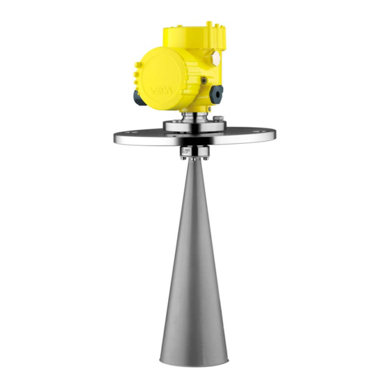
Foundation fieldbus radar sensor for continuous level measurement of bulk solids
Hide thumbs
Also See for VEGAPULS 68:
- Operating instructions manual (84 pages) ,
- Quick setup manual (24 pages) ,
- Product information (20 pages)

Related Manuals for Vega VEGAPULS 68


Summary of Contents for Vega VEGAPULS 68
-
Page 1: Operating Instructions
Operating Instructions Radar sensor for continuous level measurement of bulk solids VEGAPULS 68 Foundation Fieldbus Document ID: 36538... - Page 2 Measured value indication - Selection of national language ........... 43 Parameter adjustment ....................43 Saving the parameterisation data ................... 59 Setup with PACTware Connect the PC ......................60 Parameter adjustment ....................60 Saving the parameterisation data ................... 61 Set up with other systems VEGAPULS 68 • Foundation Fieldbus...
- Page 3 11.4 Industrial property rights ....................99 11.5 Trademark ........................99 Safety instructions for Ex areas Take note of the Ex specific safety instructions for Ex applications. These instructions are attached as documents to each instrument with Ex approval and are part of the operating instructions manual. Editing status: 2017-04-03 VEGAPULS 68 • Foundation Fieldbus...
-
Page 4: Symbols Used
Action This arrow indicates a single action. Sequence of actions Numbers set in front indicate successive steps in a procedure. Battery disposal This symbol indicates special information about the disposal of bat- teries and accumulators. VEGAPULS 68 • Foundation Fieldbus... -
Page 5: For Your Safety
During work on and with the device the required personal protective equipment must always be worn. Appropriate use VEGAPULS 68 is a sensor for continuous level measurement. You can find detailed information about the area of application in chapter "Product description". Operational reliability is ensured only if the instrument is properly used according to the specifications in the operating instructions manual as well as possible supplementary instructions. -
Page 6: Eu Conformity
• If necessary, existing viewing windows in the vessel must be coated with a microwave impermeable material (e.g. electrically conductive coating) VEGAPULS 68 • Foundation Fieldbus... -
Page 7: Radio License For Usa
This device has been approved for both closed containers and open- air environments with the following limitations: • Closed Containers: For installations utilizing a tilt during installa- tion: This device is limited to installation in a completely enclosed VEGAPULS 68 • Foundation Fieldbus... - Page 8 Cuves fermées : Pour les installations impliquant une inclinaison lors de l'installation : cet appareil ne doit être installé que dans une cuve totalement fermée en en métal, en béton ou en matière plas- tiqe renforcée de fibres de verre, pour empêcher les émissions RF VEGAPULS 68 • Foundation Fieldbus...
-
Page 9: Environmental Instructions
That is why we have introduced an environment management system with the goal of continuously improving company environmental pro- tection. The environment management system is certified according to DIN EN ISO 14001. Please help us fulfil this obligation by observing the environmental instructions in this manual: • Chapter "Packaging, transport and storage" • Chapter "Disposal" VEGAPULS 68 • Foundation Fieldbus... -
Page 10: Product Description
Alternatively, you can access the data via your smartphone: • Download the smartphone app "VEGA Tools" from the "Apple App Store" or the "Google Play Store" • Scan the Data Matrix code on the type label of the instrument or •... -
Page 11: Principle Of Operation
Principle of operation Application area The VEGAPULS 68 is a radar sensor for continuous measurement of bulk solids also under arduous process conditions and large measur- ing ranges. It the ideal solution for level measurement in high silos, large bunkers, stone crushers and melting furnaces. With different antenna versions and materials, this sensor is the optimum solution for virtually all applications and processes. -
Page 12: Packaging, Transport And Storage
The integrated Bluetooth module (optional) enables wireless adjust- ment via standard adjustment devices: • Smartphone/tablet (iOS or Android operating system) • PC/notebook with Bluetooth USB adapter (Windows operating system) You can find further information in the operating instructions "Display and adjustment module PLICSCOM" (Document-ID 27835). VEGAPULS 68 • Foundation Fieldbus... - Page 13 USB interface of a PC. For parameter adjustment of these instruments, the adjustment software PACTware with VEGA-DTM is required. You can find further information in the operating instructions "Interface adapter VEGACONNECT" (Document-ID 32628). The VEGADIS 81 is an external display and adjustment unit for VEGA VEGADIS 81 plics sensors. ®...
- Page 14 Foundation Fieldbus" (Document-ID 45111). Antenna impedance cone The antenna impedance cone is a replacement part used for optimum transmission of microwaves and for sealing against the process. You find further information in the operating instructions "Antenna impedance cone VEGAPULS 62 and 68" (Document-ID 31381). VEGAPULS 68 • Foundation Fieldbus...
-
Page 15: Mounting 4.1 General Instructions
The free openings for the cable glands are therefore covered with red dust protection caps as transport protection. The dust protection caps do not provide sufficient protection against moisture. VEGAPULS 68 • Foundation Fieldbus... -
Page 16: Mounting Preparations
Antenna Caution: A secure hold of the antenna is only ensured with the untwist guard. The untwist guards inserted on site must hence be used again. Depending on temperature range and antenna material, these are VEGAPULS 68 • Foundation Fieldbus... - Page 17 On the version with rinsing air connection, make sure that the holes in the antenna and in the process fitting coincide. This ensures a suf- ficient air flow (the air is led through the holes to the feed system. A rinsing of the whole parabolic antenna is not intended). Fig. 3: Dismounting, parabolic antenna Connection piece Compression nut Counter nut Parabolic antenna VEGAPULS 68 • Foundation Fieldbus...
-
Page 18: Mounting Preparations - Parabolic Antenna
On the version with rinsing air connection, make sure that the holes in the antenna and in the process fitting coincide. This ensures a suf- ficient air flow (the air is led through the holes to the feed system. A rinsing of the whole parabolic antenna is not intended). Fig. 4: Dismounting, parabolic antenna Connection piece Compression nut Counter nut Parabolic antenna VEGAPULS 68 • Foundation Fieldbus... -
Page 19: Mounting Instructions
In such cases, we recommend repeating the false signal suppression at a later date with existing buildup. Mounting should not be too close to the inflowing material as the Inflowing medium microwave signal will be interferred. The optimum mounting position is on the opposite of the filling. To avoid strong pollution, the distance to the filter or dust extraction must be as big as possible. VEGAPULS 68 • Foundation Fieldbus... - Page 20 4 Mounting Fig. 7: Mounting of the radar sensor with inflowing medium With bulk solids silos with lateral pneumatic filling, mounting should not be in the filling stream as the microwave signal will be interferred. The optimum mounting position is next to the filling. To avoid strong pollution, the distance to the filter or dust extraction must be as big as possible. VEGAPULS 68 • Foundation Fieldbus...
- Page 21 4 Mounting Fig. 8: Mounting of the radar sensor with inflowing medium Mounting socket The socket piece should be dimensioned in such a way that the antenna end protrudes slightly out of the socket. VEGAPULS 68 • Foundation Fieldbus...
- Page 22 When using a swivelling holder, keep in mind that the distance between antenna and socket gets smaller as the inclination of the sensor increases. Additional false reflections may be generated which can influence the measuring result at close range. Max. torque see chapter "Technical data" Fig. 11: Distance between antenna and socket with horn antenna VEGAPULS 68 • Foundation Fieldbus...
- Page 23 The antenna length can be selected (either ex works or later) to allow the antenna to protrude slightly out of the end of the mounting socket. Due to the antenna extension however, disturbing reflections are generated in the close-up range. This can lead to an increase in the VEGAPULS 68 • Foundation Fieldbus...
- Page 24 If mounting in the centre of the silo is not possible, the sensor can be directed to the vessel center by using the optional swivelling holder. The following description shows a simple way to determine the required angle of inclination. VEGAPULS 68 • Foundation Fieldbus...
- Page 25 4 Mounting Fig. 15: Proposal for installation after orientation VEGAPULS 68 The angle of inclination depends on the vessel dimensions. It can be easily checked with a suitable level or water leve on the sensor. The following table specifies the distance "a" between installation position and vessel centre dependent on the measuring distance for inclination angles of 2°...
- Page 26 Proceed as follows to align the sensor with the swivelling holder: 1. Loosen terminal screw of the swivelling holder with a fork spanner SW 13 Fig. 16: VEGAPULS 68 with swivelling holder Terminal screw Information: The hexagon screws must not be loosened.
- Page 27 Large material heaps are detected with several sensors, which can be mounted on e.g. traverse cranes. For this type of application, it is best to orient the sensor toward the solid surface. A mutual infuence of the sensors is not possible. VEGAPULS 68 • Foundation Fieldbus...
- Page 28 Fig. 19: Radar sensors on traverse crane Information: Keep in mind that for these applications, the sensors are designed for relatively slow level changes. When using VEGAPULS 68 on a mov- able bracket, the max. measuring rate must be observed (see chapter "Technical data").
- Page 29 The optimal mounting position is on the outer wall of the silo with the sensor directed towards the emptying aperture in the silo center. VEGAPULS 68 • Foundation Fieldbus...
- Page 30 4 Mounting Fig. 22: Mounting of VEGAPULS 68 in multiple chamber silos Fig. 23: Orientation of VEGAPULS 68 for emptying in the silo center Dust deposits To avoid strong buildup and dust in the antenna system, the sensor should not be mounted directly at the dust extraction of the vessel.
- Page 31 4 Mounting Fig. 24: Purging air connection with horn antenna Fig. 25: Purging air connection with parabolic antenna The practice has shown that a pressure of approx. 0.2 … 1 bar provides a sufficient air flow (see diagram in chapter "Technical data", "Purging air connection". VEGAPULS 68 • Foundation Fieldbus...
-
Page 32: Connecting To The Bus System 5.1 Preparing The Connection
In systems with potential equalisation, connect the cable screen directly to ground potential at the power supply unit, in the connection box and at the sensor. The screen in the sensor must be connected VEGAPULS 68 • Foundation Fieldbus... -
Page 33: Connecting
1 cm (0.4 in) of insulation from the ends of the individual wires 5. Insert the cable into the sensor through the cable entry Fig. 26: Connection steps 5 and 6 - Single chamber housing VEGAPULS 68 • Foundation Fieldbus... - Page 34 9. Tighten the compression nut of the cable entry gland. The seal ring must completely encircle the cable 10. Reinsert the display and adjustment module, if one was installed 11. Screw the housing lid back on The electrical connection is finished. VEGAPULS 68 • Foundation Fieldbus...
-
Page 35: Wiring Plan, Single Chamber Housing
6 7 8 Fig. 29: Electronics compartment - double chamber housing Internal connection to the terminal compartment Contact pins for the display and adjustment module or interface adapter Simulation switch ("1" = mode for simulation release) VEGAPULS 68 • Foundation Fieldbus... - Page 36 Terminal compart- ment - Radio module PLICSMOBILE Status SIM-Card Test Fig. 31: Terminal compartment - Radio module PLICSMOBILE Voltage supply You can find detailed information on connection in the supplementary instructions "PLICSMOBILE GSM/GPRS radio module". VEGAPULS 68 • Foundation Fieldbus...
-
Page 37: Wiring Plan, Double Chamber Housing Ex D Ia
Fig. 34: Top view of the plug connector Pin 1 Pin 2 Pin 3 Pin 4 Contact pin Colour, connection ca- Terminal, electronics ble in the sensor module Pin 1 Brown VEGAPULS 68 • Foundation Fieldbus... -
Page 38: Double Chamber Housing With Vegadis-Adapter
Fig. 36: View to the plug connector M12 x 1 Pin 1 Pin 2 Pin 3 Pin 4 Contact pin Colour, connection ca- Terminal, electronics ble in the sensor module Pin 1 Brown Pin 2 White Pin 3 Blue Pin 4 Black VEGAPULS 68 • Foundation Fieldbus... -
Page 39: Wiring Plan - Version Ip 66/Ip 68, 1 Bar
Brown (+) and blue (-) to power supply or to the processing system Shielding Switch-on phase After VEGAPULS 68 is connected to the bus system, the instrument carries out a self-test for approx. 30 seconds. The following steps are carried out: •... -
Page 40: Set Up With The Display And Adjustment Module 6.1 Insert Display And Adjustment Module
The display and adjustment module is powered by the sensor, an ad- ditional connection is not necessary. Fig. 38: Installing the display and adjustment module in the electronics compart- ment of the single chamber housing VEGAPULS 68 • Foundation Fieldbus... -
Page 41: Adjustment System
In the terminal compartment Note: If you intend to retrofit the instrument with a display and adjustment module for continuous measured value indication, a higher lid with an inspection glass is required. Adjustment system Fig. 40: Display and adjustment elements LC display Adjustment keys • Key functions [OK] key: VEGAPULS 68 • Foundation Fieldbus... - Page 42 (with inspection window) of the sensor housing. Fig. 41: Display and adjustment elements - with adjustment via magnetic pen LC display Magnetic pen Adjustment keys Bluetooth symbol Lid with inspection window VEGAPULS 68 • Foundation Fieldbus...
-
Page 43: Measured Value Indication - Selection Of National Language
The instrument is adapted to the application conditions via the pa- rameter adjustment. The parameter adjustment is carried out with an adjustment menu. Main menu The main menu is divided into five sections with the following func- tions: Setup: Settings, for example, for medium, application, vessel, adjust- ment, damping VEGAPULS 68 • Foundation Fieldbus... - Page 44 With this menu item, the sensor can be adapted to the applications. The adjustment possibilities depend on the selection "Liquid" or "Bulk solid" under "Medium". The following options are available when "Liquid" is selected: VEGAPULS 68 • Foundation Fieldbus...
- Page 45 – Slight foam generation – Overfilling possible • Properties, sensor: – Low sensitivity to sporadic false echoes – Stable and reliable measured values through averaging – High accuracy, because not set for max. speed – False signal suppression recommended VEGAPULS 68 • Foundation Fieldbus...
- Page 46 – Sporadic false echoes are suppressed – False signal suppression recommended Standpipe: • Medium speed: very fast filling and emptying • Vessel: – Vent hole – Joins like flanges, weld joints – Shifting of the running time in the tube • Process/measurement conditions: – Condensation VEGAPULS 68 • Foundation Fieldbus...
- Page 47 Transportable plastic tank: • Vessel: – Material and thickness different – Measurement through the vessel top • Process/measurement conditions: – Measured value jump with vessel change • Properties, sensor: – Quick adaptation to changing reflection conditions due to ves- sel change – False signal suppression required VEGAPULS 68 • Foundation Fieldbus...
- Page 48 – Sensor accepts all measured value changes within the measur- ing range immediately – High sensitivity to interference, because virtually no averaging Caution: If liquids with different dielectric constants separate in the vessel, for example through condensation, the radar sensor can detect under certain circumstances only the medium with the higher dielectric VEGAPULS 68 • Foundation Fieldbus...
- Page 49 To indicate the actual level, the measured distance must be assigned to a certain height percentage. To perform the adjustment, enter the distance with full and empty ves- sel, see the following example: VEGAPULS 68 • Foundation Fieldbus...
- Page 50 2. Edit the percentage value with [OK] and set the cursor to the requested position with [->]. 3. Set the requested percentage value with [+] and save with [OK]. The cursor jumps now to the distance value. VEGAPULS 68 • Foundation Fieldbus...
- Page 51 The default setting is a damping of 0 s. Setup - Lock adjustment In this menu item, the PIN is activated/deactivated permanently. Entering a 4-digit PIN protects the sensor data against unauthorized access and unintentional modifications. If the PIN is activated perma- nently, it can be deactivated temporarily (i.e. for approx. 60 min.) in any menu item. VEGAPULS 68 • Foundation Fieldbus...
- Page 52 • Height Display - Backlight The optionally integrated background lighting can be switched on via the adjustment menu. This function depends on the level of the supply voltage, see operating instructions of the respective sensor. VEGAPULS 68 • Foundation Fieldbus...
- Page 53 In this menu item you simulate measured values via the signal output. Diagnosis - Simulation Hence, the signal path can be tested via the segment coupler up to the input card of the control system. VEGAPULS 68 • Foundation Fieldbus...
- Page 54 "dB" over the entire measuring range. A comparison of echo curve and false signal suppression allows a more detailed statement about measurement reliability. The selected curve is continuously updated. A submenu with zoom functions is opened with the [OK] key: • "X-Zoom": Zoom function for the meas. distance • "Y-Zoom": 1, 2, 5 and 10x signal magnification in "dB" • "Unzoom": Reset the presentation to the nominal measuring range without magnification VEGAPULS 68 • Foundation Fieldbus...
- Page 55 By activating the appropriate curve, the volume percentage of the vessel is displayed correctly. If the volume should not be displayed in percent but e.g. in l or kg, a scaling can be also set in the menu item "Display". VEGAPULS 68 • Foundation Fieldbus...
- Page 56 • Basic settings: Resetting of the parameter settings incl. special parameters to the default values of the respective instrument. Any created false signal suppression, user programmable linearization curve, measured value memory as well as event memory will be deleted. VEGAPULS 68 • Foundation Fieldbus...
- Page 57 • Peak values, measured value: Resets the measured min. and max. distances to the current measured value. Select the requested reset function [->] and confirm with [OK]. The following table shows the default values of VEGAPULS 68: Menu section Menu item Default value Setup...
- Page 58 PC. Info - Device ID In this menu item, the FF Device ID of the instrument will be dis- played: VEGAPULS 68 • Foundation Fieldbus...
-
Page 59: Saving The Parameterisation Data
If it is necessary to exchange a sensor, the display and adjustment module is inserted into the replacement instrument and the data are likewise written into the sensor via the menu item "Copy device settings". VEGAPULS 68 • Foundation Fieldbus... -
Page 60: Setup With Pactware 7.1 Connect The Pc
Further setup steps are described in the operating instructions manu- al "DTM Collection/PACTware" attached to each DTM Collection and which can also be downloaded from the Internet. Detailed descrip- tions are available in the online help of PACTware and the DTMs. VEGAPULS 68 • Foundation Fieldbus... -
Page 61: Saving The Parameterisation Data
The standard version is available as a download under www.vega.com/downloads and "Software". The full version is avail- able on CD from the agency serving you. Saving the parameterisation data We recommend documenting or saving the parameterisation data via PACTware. -
Page 62: Dd Adjustment Programs
This software is updated via the Internet and new EDDs are automatically accepted into the device catalogue of this software after they are released by the manufacturer. They can then be transferred to a Field Communicator. VEGAPULS 68 • Foundation Fieldbus... -
Page 63: Diagnosis, Asset Management And Service 9.1 Maintenance
The memory is divided into two sections: Echo curve of the setup: This is used as reference echo curve for the measurement conditions during setup. Changes in the measure- ment conditions during operation or buildup on the sensor can thus be recognized. The echo curve of the setup is stored via: VEGAPULS 68 • Foundation Fieldbus... -
Page 64: Asset Management Function
This status message is inactive by default. It can be activated by the user via PACTware/DTM or EDD. Out of specification: The measured value is unreliable because an instrument specification was exceeded (e.g. electronics temperature). This status message is inactive by default. It can be activated by the user via PACTware/DTM or EDD. Maintenance: Due to external influences, the instrument function is limited. The measurement is affected, but the measured value is VEGAPULS 68 • Foundation Fieldbus... - Page 65 Error in the cali- • Error in the EEPROM bration • • F261 Error during setup Repeat setup Bit 9 • • False signal suppression faulty Repeat reset Error in the config- • Error when carrying out a reset uration VEGAPULS 68 • Foundation Fieldbus...
- Page 66 Load XML file with sensor data Error during the re- status into the sensor set "delivery status" • • M501 Hardware error EEPROM Exchanging the electronics Bit 14 • Send instrument for repair Error in the non- active linearisation table VEGAPULS 68 • Foundation Fieldbus...
-
Page 67: Rectify Faults
• Constant level • Filling • Emptying The images in column "Error pattern" show the real level as a broken line and the level displayed by the sensor as a continuous line. VEGAPULS 68 • Foundation Fieldbus... - Page 68 Amplitude or position of a false Determine the reason for the signal has changed (e.g. con- changed false signals, carry out densation, buildup); false signal false signal suppression, e.g. suppression no longer matches with condensation actual conditions VEGAPULS 68 • Foundation Fieldbus...
- Page 69 Remove contamination on the time antenna • Minimize interfering installations in the close range by changing the polarization direction • After eliminating the false sig- nals, the false signal suppres- sion must be deleted. Carry out a new false signal suppression VEGAPULS 68 • Foundation Fieldbus...
-
Page 70: Exchanging The Electronics Module
24 hour service hotline Should these measures not be successful, please call in urgent cases the VEGA service hotline under the phone no. +49 1805 858550. The hotline is also available outside normal working hours, seven days a week around the clock. -
Page 71: Software Update
Clean the instrument and pack it damage-proof • Attach the completed form and, if need be, also a safety data sheet outside on the packaging • Please contact the agency serving you to get the address for the return shipment. You can find the agency on our home page www.vega.com. VEGAPULS 68 • Foundation Fieldbus... -
Page 72: Dismounting Steps
Pass the instrument directly on to a spe- cialised recycling company and do not use the municipal collecting points. These may be used only for privately used products according to the WEEE directive. VEGAPULS 68 • Foundation Fieldbus... -
Page 73: Technical Data
DIN from DN 25, ASME from 1" Weights Ʋ Instrument (depending on housing, approx. 2 … 17.2 kg (4.409 … 37.92 lbs) process fitting and antenna) Ʋ Antenna extension 1.6 kg/m (1.157 lbs/ft) Length antenna extension max. 5.85 m (19.19 ft) VEGAPULS 68 • Foundation Fieldbus... - Page 74 Ʋ ø 40 mm (1.575 in) up to 15 m (49.21 ft) Ʋ ø 48 mm (1.89 in) up to 20 m (65.62 ft) Ʋ ø 75 mm (2.953 in) up to 40 m (131.2 ft) VEGAPULS 68 • Foundation Fieldbus...
- Page 75 2 mm (0.079 in) 1,0 m (3.28 ft) - 2 mm (- 0.079 in) - 10 mm (- 0.394 in) Fig. 56: Deviation under reference conditions Reference plane Antenna edge Recommended measuring range Repeatability ≤ ±1 mm VEGAPULS 68 • Foundation Fieldbus...
- Page 76 -40 … +200 °C (-40 … +392 °F) Time span after a sudden measuring distance change by max. 0.5 m in liquid applications, max 2 m with bulk solids applications, until the output signal has taken for the first time 90 % of the final value (IEC 61298-2). Outside the specified beam angle, the energy level of the radar signal is 50% (-3 dB) less. EIRP: Equivalent Isotropic Radiated Power. Not with steam. Not with steam. VEGAPULS 68 • Foundation Fieldbus...
- Page 77 3.9 m 1.8 m 0.9 bar (13.05 psig) 4.0 m 2.1 m 1 bar (14.5 psig) 4.2 m 2.2 m 1.5 bar (21.76 psig) 5.0 m 3.2 m 2 bar (29.0 psig) 5.5 m 4.5 m VEGAPULS 68 • Foundation Fieldbus...
- Page 78 ● – ● steel Wire cross-section (spring-loaded terminals) Ʋ Massive wire, stranded wire 0.2 … 2.5 mm² (AWG 24 … 14) Ʋ Stranded wire with end sleeve 0.2 … 1.5 mm² (AWG 24 … 16) VEGAPULS 68 • Foundation Fieldbus...
- Page 79 Ʋ mounted in the housing without lid IP 40 Materials Ʋ Housing Ʋ Inspection window Polyester foil Functional safety SIL non-reactive Interface to the external display and adjustment unit Data transmission Digital (I²C-Bus) Connection cable Four-wire VEGAPULS 68 • Foundation Fieldbus...
- Page 80 Ʋ Ex-d-ia instrument No lighting possible (integrated ia barrier) Power supply by/max. number of sensors Ʋ Fieldbus max. 32 (max. 10 with Ex) Potential connections and electrical separating measures in the instrument Electronics Not non-floating Ground terminal Galvanically connected with the metal process fitting VEGAPULS 68 • Foundation Fieldbus...
-
Page 81: Supplementary Information Foundation Fieldbus
Instruments with approvals can have different technical specifications depending on the version. For that reason the associated approval documents of these instruments have to be carefully noted. They are part of the delivery or can be downloaded under www.vega.com, "Instrument search (serial number)" as well as in the download area. 11.2 Supplementary information Foundation Fieldbus The following table gives you an overview of the instrument versions and the corresponding device descriptions, the electrical characteristics of the bus system as well as the applied function blocks. - Page 82 Discret Input (DI) PID Control Output Splitter (OS) Signal Characterizer (SC) Integrator Input Selector (IS) Arithmetic (AR) Diagnostics Standard Advanced Performance Function Blocks Instantiable General Information LAS (Link Active Scheduler) Master Capable Number of VCRs (Virtual Communication Re- lationships) VEGAPULS 68 • Foundation Fieldbus...
- Page 83 Number and makes it available to additional function blocks on its output. Fig. 59: Schematic presentation function block Discret Input (DI) Function block PID Control The function block "PID Control " is a key component for various tasks in the process automation VEGAPULS 68 • Foundation Fieldbus...
- Page 84 Optionally the function axis can be exchanged in channel 2 so that the block can be also used in a reverse control loop. VEGAPULS 68 • Foundation Fieldbus...
- Page 85 Typical input signals are AI blocks. Selection possibilities are maximum, minimum, mean value, average value and first useful signal. Through parameter combination, the block can be used as rotary switch or as preselection switch for the first useful value. Switch information can be received by other input blocks or the user. Mean value selection is also supported. VEGAPULS 68 • Foundation Fieldbus...
- Page 86 Fourth order polynomial • Simple HTG compensated level • Fourth order Polynomial Based on PV Fig. 65: Schematic presentation function block Arithmetic Parameter list The following table gives you an overview of the parameters used. VEGAPULS 68 • Foundation Fieldbus...
- Page 87 FIRMWARE_VERSION_MAIN Firmware versions major, minor, revision and build PHYSICAL_VALUES Distance, distance unit, distance status, level and status DEVICE_UNITS Distance and temperature units of the instrument APPLICATION_CONFIG Medium type, media, application type, vessel bottom, vessel height LINEARIZATION_TYPE_SEL Type of linearization VEGAPULS 68 • Foundation Fieldbus...
- Page 88 Indication value, menu language, lightning SIL_MODE EDENVELOPE_CURVE_FIL- Parameters of envelope curve filter, activation of smooth raw value curve EDDETECTION_CURVE_FIL- Parameters of the detection filter, offset threshold value curve EDECHO_COMBINATION Parameters for echo combination, function combine echoes, amplitude difference of combined echoes, position difference of combined echoes LIN_TABLE_A … LIN_ 32 couples of percentage and lin. percentage values TABLE_Q ELECTRONICS_INFORMA- Electronics version TION VEGAPULS 68 • Foundation Fieldbus...
-
Page 89: Dimensions
System noise treatment ECHO_MEM_SAVE_CURVE_ TYPE ECHO_MEM_STATE Busy, curve type, error code 11.3 Dimensions The following dimensional drawings represent only an extract of all possible versions. Detailed dimensional drawings can be downloaded at www.vega.com/downloads under "Drawings". VEGAPULS 68 • Foundation Fieldbus... - Page 90 ½ NPT Fig. 67: Housing versions with protection rating IP 66/IP 68 (0.2 bar) - with integrated display and adjustment module the housing is 9 mm/0.35 in higher Aluminium - single chamber Aluminium - double chamber VEGAPULS 68 • Foundation Fieldbus...
- Page 91 Fig. 69: Housing versions with protection rating IP 66/IP 68 (0.2 bar) - with integrated display and adjustment module the housing is 9 mm/0.35 in higher Stainless steel single chamber (electropolished) Stainless steel single chamber (precision casting) Stainless steel double chamber housing (precision casting) VEGAPULS 68 • Foundation Fieldbus...
- Page 92 ø48 3" ø75 4" ø95 inch 3.94" ø1.58" 1½" 4.72" ø1.89" 2" 8.50" ø2.95" 3" 16.93" ø3.74" 4" Fig. 71: VEGAPULS 68, horn antenna in threaded version Standard With temperature adapter up to 250 °C VEGAPULS 68 • Foundation Fieldbus...
- Page 93 11 Supplement VEGAPULS 68, horn antenna in flange version inch 3.94" ø1.58" 1½" ø40 1½" 4.72" ø1.89" 2" ø48 2" 8.50" ø2.95" 3" ø75 3" 16.93" ø3.74" 4" ø95 4" Fig. 72: VEGAPULS 68, horn antenna in flange version Standard With temperature adapter up to 250 °C VEGAPULS 68 • Foundation Fieldbus...
- Page 94 41 mm (1.61") inch 3.94" ø1.58" 1½" ø40 1½" 4.72" ø1.89" 2" ø48 2" 8.50" ø2.95" 3" ø75 3" 16.93" ø3.74" 4" ø95 4" Fig. 73: VEGAPULS 68, horn antenna in flange version with purging air connection Standard With temperature adapter up to 250 °C Blind plug Reflux valve VEGAPULS 68 • Foundation Fieldbus...
- Page 95 11 Supplement VEGAPULS 68, horn antenna in flange version 450 °C 2" ø 48 3" ø 75 4" ø 95 inch 2" 4.72" ø 1.89" 3" 8.50" ø 2.95" 4" 11.30" ø 3.74" Fig. 74: VEGAPULS 68, horn antenna in flange version with temperature adapter up to 450 °C VEGAPULS 68 • Foundation Fieldbus...
- Page 96 ø 95 inch 1½" 3.94" ø 1.58" 2" 4.72" ø 1.89" 8.50" ø 2.95" 3" 4" 16.93" ø 3.74" Fig. 75: VEGAPULS 68, horn antenna and swivelling holder Standard With temperature adapter up to 250 °C VEGAPULS 68 • Foundation Fieldbus...
- Page 97 11 Supplement VEGAPULS 68, horn antenna and swivelling holder, threaded fitting SW 70 mm (2.76") G2 / 2NPT Fig. 76: VEGAPULS 68, horn antenna and swivelling holder, threaded fitting Standard With temperature adapter up to 250 °C VEGAPULS 68 • Foundation Fieldbus...
- Page 98 11 Supplement VEGAPULS 68, parabolic antenna and swivelling holder Fig. 77: VEGAPULS 68, parabolic antenna and swivelling holder Standard With temperature adapter up to 200 °C VEGAPULS 68 • Foundation Fieldbus...
-
Page 99: Industrial Property Rights
Les lignes de produits VEGA sont globalement protégées par des droits de propriété intellec- tuelle. Pour plus d'informations, on pourra se référer au site www.vega.com. VEGA lineas de productos están protegidas por los derechos en el campo de la propiedad indus- trial. Para mayor información revise la pagina web www.vega.com. - Page 100 – PID Control 83 Vessel height 49 – Signal Characterizer 84 Vessel installations 26 – Transducer Block (TB) 83 Indication value with Foundation Fieldbus 52 Instrument units 55 Instrument version 58 Language 52 Linearisation curve 55 Lock adjustment 51 VEGAPULS 68 • Foundation Fieldbus...
- Page 101 Notes VEGAPULS 68 • Foundation Fieldbus...
- Page 102 Notes VEGAPULS 68 • Foundation Fieldbus...
- Page 103 Notes VEGAPULS 68 • Foundation Fieldbus...
- Page 104 Subject to change without prior notice © VEGA Grieshaber KG, Schiltach/Germany 2017 VEGA Grieshaber KG Phone +49 7836 50-0 Am Hohenstein 113...
Need help?
Do you have a question about the VEGAPULS 68 and is the answer not in the manual?
Questions and answers