Advertisement
Table of Contents
- 1 Using Your Appliance
- 2 Getting to Know Your Product
- 3 Hob Controls
- 4 Key Lock
- 5 Auto Heat-Up
- 6 Safety Shut down
- 7 Error Codes
- 8 Cleaning Your Appliance
- 9 Installation Instructions
- 10 Choosing Your Installation
- 11 Installation above an Oven
- 12 Dimensions and Clearances
- 13 Connect to the Electricity Supply
- 14 Technical Data
- Download this manual
Advertisement
Table of Contents

Related Manuals for Lamona LAM1744


Summary of Contents for Lamona LAM1744
- Page 1 Ceramic Touch Control Hob LAM1744 User Guide www.howdens.com/appliance-registration Part No: 083550101 Date: 07/02/2017...
- Page 3 INTRODUCTION Thank you for buying this British-built appliance from us. This user guide book is designed to help you through each step of owning your new product. Please read it carefully before you start using your appliance, as we have endeavored to answer as many questions as possible, and provide you with as much support as we can.
- Page 4 SAFETY WARNING • If the hob surface is cracked, broken or shattered, switch off the appliance to avoid the possibility of electric shock and call for a service engineer’s visit. • The appliance and its accessible parts become hot during use. Care should be taken to avoid touching heating elements.
- Page 5 If you have an electrical fire in the kitchen: • Pull the plug out, or switch off the power at the fuse box - this may be enough to stop the fire imme- diately • Smother the fire with a fire blanket, or use a dry powder or carbon dioxide extinguisher •...
-
Page 6: Using Your Appliance
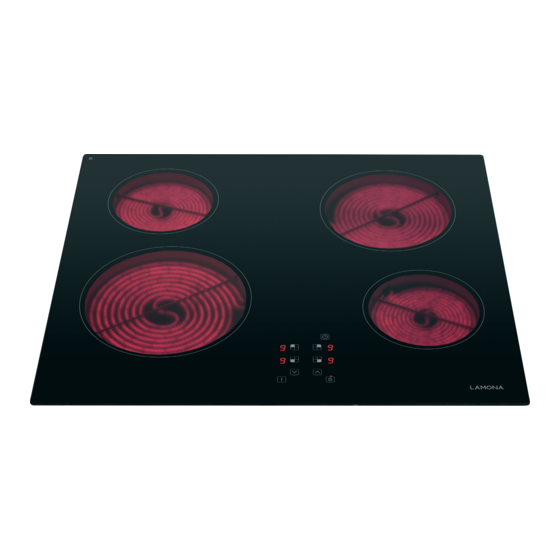
USING YOUR APPLIANCE Getting to know your product Note: Your appliance layout may differ depending on the model. Left hand rear Right hand rear Left hand front Right hand front Hob Controls COOK ZONE KEYS INDIVIDUAL COOK ZONE DISPLAYS POWER DOWN KEY POWER UP KEY ON/OFF KEY MINUTE MINDER / FAULT CODES... - Page 7 Overview Function Description Symbol Once a cook zone is selected, a power level can Power Level be set to a low or high temperature. After use, the cooking surface remains hot and the residual heat symbol will be displayed. As it cools, Residual Heat the residual heat symbol will disappear from the display.
-
Page 8: Key Lock
Key Lock Press and hold key lock to deactivate/activate. The red LED will be illuminated when active Note: If any of the cook zones are ON, the key lock function locks all the keys except the ON/OFF key. If the cook zones are OFF, the key lock function locks all the keys, including the ON/OFF key. The Key Lock is automatically activated every time the electricity supply is switched off and back on to the hob. - Page 9 Switching on an individual hob cook zone Touch and hold the on /off key for 1 second The hob will make a sound and 0 will appear in the cook zone displays Touch the required cook zone key, it will start Whilst flashing, adjust the power level by to flash using the up or down keys...
- Page 10 Switching off an individual hob cook zone Touch the required cook zone key until the Return the power level to 0 by pressing the up and down keys together zone display flashes Note: You can also touch the down key to until power level 0 appears on the display. Set a time for a cook zone Whilst the cook zone power level is flashing, touch the timer Touch the cook zone symbol for the desired...
- Page 11 Using the up or down keys, set the time required in minutes The cook zone being timed is indicated by flashing LED on the timer To check remaining time Touch the the timer symbol to check the Touch the cook zone symbol for the desired zone remaining time...
- Page 12 Adjust the set time Touch the cook zone symbol for the desired Touch the timer symbol zone Using the up or down keys, set the time required in minutes Deactivating timed cooking Touch the timer symbol Touch the cook zone symbol for the desired zone...
-
Page 13: Auto Heat-Up
Using the down key to return timer to 00 Auto heat up Press the up key and increase the Select appropriate cook zone power level to 9... - Page 14 Press the plus key again and until the Red The power level will still be flashing, so LED is illuminated next to the cook zone. now select the power level you would like Once set the Red LED is illuminated. Approx heat up time Power Level Time (min/sec)
-
Page 15: Safety Shut Down
Safety Shut Down If the power level is not changed for a long period of time the cook zone will automatically turn itself off. The maximum time a cook zone can stay on depends on the power level. Power Level Max Time (Hours) Error codes Hob status... -
Page 16: Cleaning Your Appliance
CLEANING YOUR APPLIANCE Do’s Note: Always switch off your appliance and allow it to cool down before you clean any part of it. Note: Please take extra care when cleaning over the symbols on the control panel, as this can lead to them fading. -
Page 17: Installation Instructions
INSTALLATION INSTRUCTIONS Before you start please read the instructions. Planning your installation will save you time and effort. FAILURE TO INSTALL APPLIANCES CORRECTLY IS DANGEROUS AND COULD LEAD TO PROSECUTION. Please take care when handling - we recommend the use of protective gloves during installation. Installation should only be carried out by a competent electrician / qualified technician. -
Page 18: Choosing Your Installation
CHOOSING YOUR INSTALLATION Installation above an oven Refer to the manufacturer’s instructions for clearances above the oven. We recommend a minimum 20mm gap between the bottom of the hob and appliance, should the work surface be less than 38mm deep Installation above a unit with a drawer or door If necessary, remove the front crosspiece of the unit. -
Page 19: Dimensions And Clearances
DIMENSIONS AND CLEARANCES rear wall Hobs - 53mm min Worktop cutout sizes Please see table below for hob cut out dimensions for your appliance Product X(mm) Y(mm) *60cm hob *77cm hob 737.5 487.5 The nominal dimensions are shown on the hob cut out table and must be fabricated to a toler- ance of +2.0mm -0.0mm with maximum corner radi of 4.0mm Fitting into work top Sufficient length of cable should be allowed so the hob can be removed for servicing, but make sure it... - Page 20 Cupboard / hood clearances Nominal width of the hob No shelf or overhang of combustible material should be closer than 650mm above the hob. Wall Unit Wall Unit inc cornice inc cornice 400mm 400mm 650mm 90mm 90mm worktop Self adhesive seal Apply the self adhesive seal to the underside edges of the hob glass.
- Page 21 Recessed Method (selected models) Recess the work top to the appropriate depth (Approx 5mm) and shape to fit the hob (add 1mm to over- all glass size). Refer to the installation bracket advice to determine your installation type. Insert the hob into the re- cess, ensuring that the foam seal is sitting correctly.
- Page 22 Push fit hob installation Your new hob is pre-fitted with push fit installation clips which are designed to simplify the installation procedure and retain the hob into the worktop. Care must be taken to not damage these clips whilst installing this product. Depending on your product the images below show the push fit clips...
- Page 23 Depending on your product, the images below represents how the system interacts with your worktop. Note; The worktop cut out dimensions are critical and will affect the performance of how the push fit system works. The nominal dimensions are shown on the hob cut out table and must be fabricated to a tolerance of +2.0mm -0.0mm.
-
Page 24: Connect To The Electricity Supply
CONNECT TO THE ELECTRICITY SUPPLY This appliance must be earthed. Only connect to the electrical mains terminal with the power switched off. The electrical mains terminal is live. Loose and inappropriate connections can make the terminal overheat. A device must be provided in the electrical installation which allows the appliance to be disconnected from the mains at all poles with a contact opening of at least 3mm. - Page 25 3 PHASE SUPPLY - FOR INSTALLATION IN MAINLAND EUROPE For connection to a 3 phase supply, the supplied mains cable and bridging links will need to be removed. • Firstly open the terminal block cover using a small flat bladed screwdriver in the door release tabs shown.
-
Page 26: Technical Data
RH Rear RH Front For the specific power rating of your model, refer to the data badge on the under side of your appliance. Warning: This appliance must be earthed. Product Information Commission Regulation (EU) No 66/2014 LAMONA Model LAM1744 Type of Hob Ceramic No of Cooking Zones Heating Technology Ceramic FL – 210mm RL – 145mm Diameter FR –... - Page 27 Call the Depot number on your Proof of Purchase Document supplied with the product / kitchen. Call the LAMONA Service Line on 0845 00 60 006 *Product installed within a domestic kitchen or a non-domestic kitchen where 8 or fewer people are using the appliance.
- Page 28 Product serial number (Place sticker here) ISSUE V2 060217...
Need help?
Do you have a question about the LAM1744 and is the answer not in the manual?
Questions and answers