Advertisement
Water Specialist
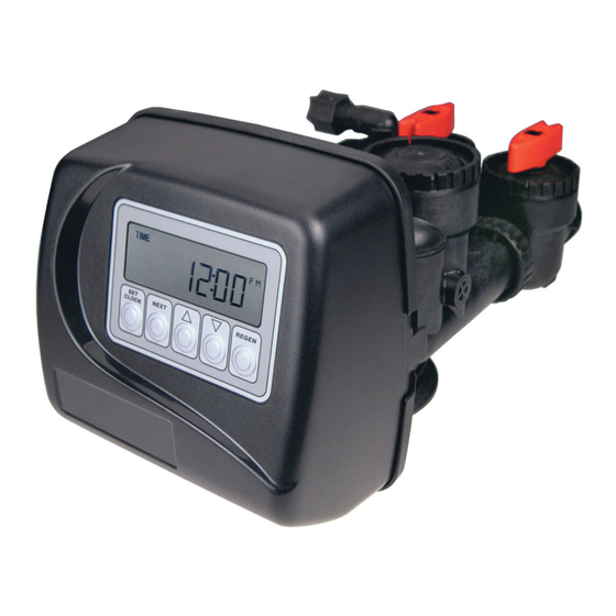
1" Control Valve Series Model: WS1
1.25" Control Valve Series Model: WS1.25
Operation and Instruction Manual for OEM Only.
Please Note: This operation and instruction manual is for the training of
the OEM and for the OEM to use to train their customers. This document
is not to be used as the complete system manual.
Advertisement
Table of Contents

Related Manuals for Clack Valve WS1.25

Summary of Contents for Clack Valve WS1.25
- Page 1 Water Specialist 1” Control Valve Series Model: WS1 1.25” Control Valve Series Model: WS1.25 Operation and Instruction Manual for OEM Only. Please Note: This operation and instruction manual is for the training of the OEM and for the OEM to use to train their customers. This document...
- Page 2 Page 2 WS1 & 1.25 Man u al...
-
Page 3: Table Of Contents
Installer Displays/Settings ........................12 User Displays/Settings ..........................12 Diagnostics ..............................14 Valve History ............................15 Drawings and Part Numbers Front Cover and Drive Assembly ......................16 FOR INFORMATION COMMON TO ALL 1” & 1.25” CONTROL VALVES REFER TO THE WS1 & WS1.25 DRAWINGS AND SERVICE MANUAL... -
Page 4: Control Valve Function And Cycles Of Operation
Table 1 shows the order of the cycles when the valve is set up as a softener. When the WS1 or WS1.25 control valve is used as a downfl ow softener, two backwashes always occur. When the WS1 or WS1.25 control valve is used as an upfl ow softener, only one backwash occurs after brining. -
Page 5: Backwash Normal Length Softener
Backwash Normal Length Softener Cycle Times in Minutes WS1 & WS1.25 Downfl ow Softener WS1 & WS1.25 Upfl ow Softener Grains Capacity/lb NaCl 6000 to 3501 3500 to 2501 2500 to 1700 6000 to 3501 3500 to 2501 2500 to 1700 Less than 7.5... -
Page 6: Cycle Times In Minutes
Page 6 WS1 & 1.25 Man u al Table 4 Regeneration Cycles Filtering WS1 & WS1.25 Downfl ow WS1 & WS1.25 Downfl ow WS1 & WS1.25 Regenerant Refi ll After Rinse Regenerant Prefi ll No Regeneration Cycle: Backwash Cycle: Fill... - Page 7 The WS1 & WS1.25 control valves can also be set to regenerate immediately or at the next regeneration time by changing the Regeneration Time Option.
-
Page 8: Oem Softener System Setup
Page 8 WS1 & 1.25 Man u al OEM General In struc tions The control valve offers multiple procedures that allow the valve to be modifi ed to suit the needs of the installation. These pro ce dures are: OEM Softener Setup OEM Filter Setup Installer Displays &... - Page 9 Prior to selecting a regenerant fl ow direction, verify the correct valve body, main piston, regenerant piston, and stack are being used, and that the injector or injector plug(s) are in the correct locations. See Valve Body Compliance Table in WS1 & WS1.25 Drawings and Service Manual.
- Page 10 Page 10 WS1 & 1.25 Man u al Setting Options Table Filters should only use shaded options. Volume Regeneration Result Capacity Time Option Override Reserve capacity automatically estimated. AUTO NORMAL Regeneration occurs when volume capacity falls below the reserve capacity at the next Regen Set Time Reserve capacity automatically estimated.
-
Page 11: Oem Filter System Setup
WS1 & 1.25 Man u al Page 11 OEM Filter System Setup Quick Reference This is a quick reference setup procedure. See OEM Filter System Setup Detail for more information on available settings. STEP 1F STEP 1F – Press NEXT and ▼ simultaneously for 3 seconds. If screen in step 2F does not appear in 5 seconds the lock on the valve is activated. - Page 12 Page 12 WS1 & 1.25 Man u al Installer Display Settings STEP 1I - Press NEXT and ▲ simultaneously for 3 seconds. STEP 1I STEP 2I – Hardness: Set the amount of hardness in grains of hardness as calcium car bon ate per gallon using ▼ or ▲. The default is 20 with value STEP 2I ranges from 1 to 150 in 1 grain increments.
- Page 13 WS1 & 1.25 Man u al Page 13 Regeneration Mode Typically a system is set to regenerate at a time of low water usage. An example of a time with low water usage is when a household is asleep. If there is a demand for water when the system is regenerating, untreated water will be used.
-
Page 14: Diagnostics
Page 14 WS1 & 1.25 Man u al STEP 1D Diagnostics STEP 1D – Press ▼ or ▲ simultaneously for three seconds. If screen in step 2D does not appear in 5 seconds the lock on the valve is activated. To unlock press ▼, NEXT, ▲, and STEP 2D SET CLOCK in sequence, then press NEXT and ▼... -
Page 15: Valve History
WS1 & 1.25 Man u al Page 15 Valve History STEP 1VH – Press ▲ and ▼ simultaneously for three seconds and release. Then STEP 1VH press ▲ and ▼ si mul ta neous ly and release. If screen in step 2VH does not appear in 5 seconds the lock on the valve is activated. -
Page 16: Front Cover And Drive Assembly
Page 16 WS1 & 1.25 Man u al Front Cover and Drive Assembly Drawing No. Order No. Description Quantity V3175-01 WS1 Front Cover ASY V3107-01 WS1 Motor V3106-01 WS1 Drive Bracket&Spring Clip V3108-10BOARD WS1 PCB XMEGA REPL V3110 WS1 Drive Reducing Gear 12x36 V3109 WS1 Drive Gear Cover V3002... - Page 17 WS1 & 1.25 Man u al Page 17...
- Page 18 Page 18 WS1 & 1.25 Man u al...
- Page 19 WS1 & 1.25 Man u al Page 19...
-
Page 20: Revision History
Page 20 WS1 & 1.25 Man u al Revision History: 5/27/2014 PAGE 13: New regeneration cycle status display, new error display PAGE 15: Step 7VH Error Log: new display PAGE 16: V3108-10BOARD WS1/125 PCB XMEGA REPLACE New board drawing 9/15/2015 PAGE 16: Drive Bracket &...
Need help?
Do you have a question about the WS1.25 and is the answer not in the manual?
Questions and answers
How much does that unit cost!?