HP ProLiant DL60 Gen9 User Manual
Hide thumbs
Also See for ProLiant DL60 Gen9:
- Maintenance and service manual (113 pages) ,
- Maintenance and service manual (104 pages)
Table of Contents
Advertisement
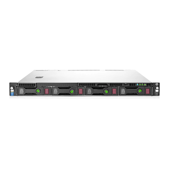
HPE ProLiant DL60 Gen9 Server
User Guide
Abstract
This document is for the person who installs, administers, and troubleshoots servers and storage systems. Hewlett Packard Enterprise
assumes you are qualified in the servicing of computer equipment and trained in recognizing hazards in products with hazardous energy
levels.
Part Number: 786245-003
April 2016
Edition: 3
Advertisement
Table of Contents

Related Manuals for HP ProLiant DL60 Gen9


Summary of Contents for HP ProLiant DL60 Gen9
-
Page 1: User Guide
HPE ProLiant DL60 Gen9 Server User Guide Abstract This document is for the person who installs, administers, and troubleshoots servers and storage systems. Hewlett Packard Enterprise assumes you are qualified in the servicing of computer equipment and trained in recognizing hazards in products with hazardous energy levels. - Page 2 © Copyright 2014, 2016 Hewlett Packard Enterprise Development LP The information contained herein is subject to change without notice. The only warranties for Hewlett Packard Enterprise products and services are set forth in the express warranty statements accompanying such products and services. Nothing herein should be construed as constituting an additional warranty.
-
Page 3: Table Of Contents
Contents Component identification ..........................6 Front panel components............................. 6 Front panel LEDs and buttons ........................... 7 Front panel LED power fault codes ......................... 8 Rear panel components ............................. 8 Rear panel LEDs ................................ 9 PCIe riser board slot definitions ..........................9 System board components ............................ - Page 4 Redundant power supply option..........................71 Power input module and RPS backplane characteristics ................71 Installing the redundant power supply option ....................71 HP Trusted Platform Module option ......................... 76 Installing the Trusted Platform Module board ....................76 Retaining the recovery key/password ......................78 Enabling the Trusted Platform Module ......................
- Page 5 Flexible boot control ............................95 Restoring and customizing configuration settings ..................96 Secure Boot configuration ..........................96 Embedded UEFI shell ........................... 96 Embedded Diagnostics option ........................97 RESTful API support for UEFI ........................97 Re-entering the server serial number and product ID .................. 97 Utilities and features ..............................
-
Page 6: Component Identification
Component identification Front panel components Item Description Optical drive (optional) Serial label pull tab The serial number/iLO information pull tab is double-sided. The top side shows the server serial number and the customer asset tag label. The reverse side shows the default iLO account information and QR code label. -
Page 7: Front Panel Leds And Buttons
Front panel LEDs and buttons Item Description Status UID button/LED Solid blue = Activated Flashing blue: • 1 flash per second = Remote management or firmware upgrade in progress • 4 flashes per second = iLO manual reboot sequence initiated •... -
Page 8: Front Panel Led Power Fault Codes
When all four LEDs described in this table flash simultaneously, a power fault has occurred. For more information, see "Power fault LEDs ("Front panel LED power fault codes" on page 8)." Front panel LED power fault codes The following table provides a list of power fault codes, and the subsystems that are affected. Not all power faults are used by all servers. -
Page 9: Rear Panel Leds
Rear panel LEDs Item Description Status UID LED Solid blue = Activated Flashing blue: • 1 flash per second = Remote management or firmware upgrade in progress • 4 flashes per second = iLO manual reboot sequence initiated • 8 flashes per second = iLO manual reboot sequence in progress Off = Deactivated NIC link LED... -
Page 10: System Board Components
System board components Item Description Primary PCIe riser board connector* TPM connector System battery SATA connector Storage backup power connector for PCIe slots 1-2 Reserved Secondary PCIe riser board connector* MicroSD slot Storage backup power connector for PCIe slot 3 System maintenance switch NMI header Reserved... -
Page 11: Dimm Slot Locations
DIMM slot locations DIMM slots are numbered sequentially (1 through 4) for each processor. The supported AMP modes use the letter assignments for population guidelines. The arrow points to the front of the server. System maintenance switch Position Default Function Off = iLO 4 security is enabled. -
Page 12: Nmi Functionality
CAUTION: Clearing CMOS and/or NVRAM deletes configuration information. Be sure to properly configure the server or data loss could occur. Before using the S7 switch to change the boot mode to Legacy BIOS Mode, you must first disable the Dynamic Smart Array B140i Controller. To disable the Dynamic Smart Array B140i Controller: Reboot the server. -
Page 13: Hot-Plug Drive Led Definitions
Hot-plug drive LED definitions Item Status Definition Locate Solid blue The drive is being identified by a host application. Flashing blue The drive carrier firmware is being updated or requires an update. Activity ring Rotating green Drive activity No drive activity Do not remove Solid white Do not remove the drive. -
Page 14: Fan Locations
Fan locations Component identification 14... -
Page 15: Operations
Operations Power up the server Connect each power cord to the server. Connect each power cord to the power source. Press the Power On/Standby button. The server exits standby mode and applies full power to the system. The system power LED changes from amber to green. - Page 16 If the rear panel cables are not secured by a cable management arm, do the following: Power down the server (on page 15). Disconnect all peripheral cables from the server. Disconnect each power cord from the server. Do one of the following: In a server that uses thumbscrew rack ears, loosen the captive thumbscrews that secure the server faceplate to the front of the rack, and then slide the server out of the rack.
-
Page 17: Access The Product Rear Panel
In a server that uses quick-release latch rack ears, if necessary, tighten the shipping screws. If the rear panel cables were disconnected because a cable management arm is not in use, do the following: Connect each power cord to the server. Connect all peripheral cables to the server. -
Page 18: Remove The Server From The Rack
Remove the server from the rack WARNING: This server is very heavy. To reduce the risk of personal injury or damage to the equipment: • Observe local occupational health and safety requirements and guidelines for manual material handling. • Get help to lift and stabilize the product during installation or removal, especially when the product is not fastened to the rails. -
Page 19: Install The Access Panel
CAUTION: To prevent damage to electrical components, take the appropriate anti-static precautions before beginning any installation, removal, or replacement procedure. Improper grounding can cause electrostatic discharge. CAUTION: Do not operate the server for long periods with the access panel open or removed. -
Page 20: Install The Air Baffle
To remove the component: Power down the server (on page 15). If you are performing a non-hot-plug procedure, remove all power: Disconnect each power cord from the power source. Disconnect each power cord from the server. Do one of the following: Extend the server from the rack (on page 15). -
Page 21: Remove The Pci Riser Cage
To install the component: Install the air baffle. Install the access panel (on page 19). Do one of the following: Slide the server into the rack. Install the server into the rack. Power up the server (on page 15). Remove the PCI riser cage WARNING: To reduce the risk of personal injury from hot surfaces, allow the drives and the internal system components to cool before touching them. - Page 22 Secondary PCI riser cage PCI blank Operations 22...
-
Page 23: Install The Pci Riser Cage
Remove any expansion boards installed in the primary riser cage. Remove the primary PCI riser cage. Install the PCI riser cage CAUTION: To prevent damage to the server or expansion boards, power down the server, and disconnect all power cords before removing or installing the PCI riser cage. To install the component: Operations 23... - Page 24 Align the PCI riser board with the corresponding connectors on the system board, and then press down the PCI riser cage. If installing the secondary PCI riser cage, remove the PCI blank. Retain the blank and screws for future use. Align the PCI riser board with the corresponding connectors on the system board, and then press down the PCI riser cage.
- Page 25 Tighten the two screws to secure the cage. Install the access panel (on page 19). Do one of the following: Slide the server into the rack. Install the server into the rack. Power up the server (on page 15). Operations 25...
-
Page 26: Setup
Setup Optional services Delivered by experienced, certified engineers, HPE support services help you keep your servers up and running with support packages tailored specifically for HPE ProLiant systems. HPE support services let you integrate both hardware and software support into a single package. A number of service level options are available to meet your business and IT needs. -
Page 27: Temperature Requirements
CAUTION: To prevent improper cooling and damage to the equipment, do not block the ventilation openings. When vertical space in the rack is not filled by a server or rack component, the gaps between the components might cause changes in airflow through the rack and across the servers. To maintain airflow cover all gaps with blanking panels. -
Page 28: Electrical Grounding Requirements
When installing more than one server, you might need to use additional power distribution devices to safely provide power to all devices. Observe the following guidelines: • Balance the server power load between available AC supply branch circuits. • Do not allow the overall system AC current load to exceed 80% of the branch circuit AC current rating. -
Page 29: Rack Warnings
CAUTION: Do not operate the server for long periods with the access panel open or removed. Operating the server in this manner results in improper airflow and improper cooling that can lead to thermal damage. Rack warnings WARNING: To reduce the risk of personal injury or damage to the equipment, be sure that: •... -
Page 30: Installing Hardware Options
If you are installing the server into a telco rack, order the appropriate option kit at the RackSolutions.com website (http://www.racksolutions.com/hp). Follow the server-specific instructions on the website to install the rack brackets. WARNING: This server is very heavy. To reduce the risk of personal injury or damage to the equipment: •... - Page 31 If the clip is positioned too near the power cord that it blocks the power cord plug connection, slide the clip backward. Connect the power cord to the server. Press the top part of the clip, and then pull the clip open. Position the power cord inside the clip, and then close the clip.
- Page 32 Slide the clip forward until it is flush against the edge of the power cord plug. For a server using a hot-plug power supply: To prevent accidental power cord disconnection when sliding the server in and out of the rack, secure the power cord in the strain relief strap attached to the power input module handle: Unwrap the strain relief strap from the power input module handle.
-
Page 33: Installing The Rack Rail Hook-And-Loop Strap
Secure the power cord with the strain relief strap. Employ best practices to route and manage the power cords and other cables in the server rear panel. IMPORTANT: When using cable management arm components, be sure to leave enough slack in each of the cables to prevent damage to the cables when the server is extended from the rack. -
Page 34: Installing The Operating System
Loop the end of the hook-and-loop strap through the buckle. When multiple hook-and-loop straps are used in the same rack, stagger the strap location, so that the straps are adjacent to each other when viewed from top to bottom. This positioning will enable the rack rail to slide easily in and out of the rack. -
Page 35: Powering On And Selecting Boot Options In Uefi Boot Mode
For additional system software and firmware updates, download the Service Pack for ProLiant from the Hewlett Packard Enterprise website (http://www.hpe.com/servers/spp/download). Software and firmware must be updated before using the server for the first time, unless any installed software or components require an older version. For more information, see "Keeping the system current (on page 99)."... -
Page 36: Hardware Options Installation
Hardware options installation Introduction If more than one option is being installed, read the installation instructions for all the hardware options and identify similar steps to streamline the installation process. WARNING: To reduce the risk of personal injury from hot surfaces, allow the drives and the internal system components to cool before touching them. -
Page 37: Drive Installation Guidelines
Drive installation guidelines When adding drives to the server, observe the following general guidelines: • The system automatically sets all device numbers. • Populate drive bays, based on the drive numbering sequence. Start from the drive bay with the lowest device number ("Drive numbering"... -
Page 38: Installing A Hot-Plug Drive
Install the drive in the carrier. Install the drive. CAUTION: To prevent improper cooling and thermal damage, do not operate the server unless all bays are populated with either a component or a blank. If removed, install the security bezel ("Security bezel option"... -
Page 39: Storage Controller Options
Remove the drive blank. Prepare the drive. Install the drive. Determine the status of the drive from the drive LED definitions ("Hot-plug drive LED definitions" on page 13). If removed, install the security bezel ("Security bezel option" on page 36). To configure arrays, see the HPE Smart Storage Administrator User Guide on the Hewlett Packard Enterprise website (http://www.hpe.com/info/smartstorage/docs). -
Page 40: Installing A Storage Controller And Fbwc Module
To configure arrays, see the HPE Smart Storage Administrator User Guide on the Hewlett Packard Enterprise website (http://www.hpe.com/info/smartstorage/docs). The server supports FBWC. FBWC consists of a cache module and a Smart Storage Battery Pack. The DDR cache module buffers and stores data being written by an integrated Gen9 P-series Smart Array Controller. - Page 41 Remove the secondary PCI riser cage ("Remove the PCI riser cage" on page 21). CAUTION: When connecting or disconnecting the cache module cable, the connectors on the cache module and cable are susceptible to damage. Avoid excessive force and use caution to avoid damage to these connectors.
-
Page 42: Installing A Smart Storage Battery
Install the access panel (on page 19). Do one of the following: Slide the server into the rack. Install the server into the rack. Power up the server (on page 15). If you are planning to install new drives, install them now. For more information about the integrated storage controller and its features, select the relevant user documentation on the Hewlett Packard Enterprise website (http://www.hpe.com/info/smartstorage/docs). -
Page 43: Drive Cable Options
Install the access panel (on page 19). Do one of the following: Slide the server into the rack. Install the server into the rack. Power up the server (on page 15). Drive cable options Use these drive cable options to install a Host Bus Adapter or a Smart Array Controller board option. For more information about product features, specifications, options, configurations, and compatibility, see the product QuickSpecs on the Hewlett Packard Enterprise website (http://www.hpe.com/info/qs). - Page 44 Route the Mini-SAS cables through the clip and connect the connectors to the drive backplane. H240 Host Bus Adapter to the 4 LFF drive backplane P440 Smart Array Controller to the 4 LFF drive backplane Connect the rest of the drive cables required in this drive configuration. For more information, see "Storage cabling (on page 80)."...
-
Page 45: Optical Drive Option
Optical drive option For more information about product features, specifications, options, configurations, and compatibility, see the product QuickSpecs on the Hewlett Packard Enterprise website (http://www.hpe.com/info/qs). To install the component: Power down the server (on page 15). Remove all power: Disconnect each power cord from the power source. Disconnect each power cord from the server. -
Page 46: Redundant Fan Option
Install the optical drive into the bay. Connect the optical drive cable to the optical drive. Route the optical drive cable through the cable clip, connect the cable to the system board SATA connector, and then connect the power cable to the system board power cable connector: Install the access panel (on page 19). -
Page 47: Fan Population Guidelines
Fan population guidelines Configuration Fan bay Fan bay Fan bay Fan bay Fan bay Fan bay Blank Blank Blank One processor, non-redundant Blank One processor, redundant Blank Blank Two processors, non-redundant Two processors, redundant • In the redundant fan mode: If one fan rotor fails, the system continues to operate without redundancy. - Page 48 To determine which fan blanks need to be removed to install the additional fans, see "Fan population guidelines." Remove the fan blank. Install the fan. CAUTION: The fan does not have a fan guard. Special attention is needed when removing or installing the fan to prevent finger injury.
-
Page 49: Memory Options
Install the server into the rack. Power up the server (on page 15). Memory options IMPORTANT: This server does not support mixing LRDIMMs and RDIMMs. Attempting to mix any combination of these DIMMs can cause the server to halt during BIOS initialization. The memory subsystem in this server can support LRDIMMs or RDIMMs: •... -
Page 50: Smartmemory
Populated DIMM speed (MT/s) Operating memory speed is a function of rated DIMM speed, the number of DIMMs installed per channel, processor model, and the speed selected in the BIOS/Platform Configuration (RBSU) of the UEFI System Utilities ("HPE UEFI System Utilities"... -
Page 51: Memory Subsystem Architecture
Qualified memory is performance-tuned for ProLiant and BladeSystem servers and provides future enhanced support through Active Health and manageability software. Memory subsystem architecture The memory subsystem in this server is divided into channels. Each processor supports four channels, and each channel supports one DIMM slot. Channel Population order Slot number... -
Page 52: Dimm Identification
DIMM identification To determine DIMM characteristics, see the label attached to the DIMM and refer to the following illustration and table. Item Description Definition Capacity 8 GB 16 GB 32 GB 64 GB Rank 1R = Single-rank 2R = Dual-rank 4R = Quad-rank Data width on DRAM x4 = 4-bit... -
Page 53: General Dimm Slot Population Guidelines
ECC mode. For more information, see the HPE UEFI System Utilities User Guide for HPE ProLiant Gen9 Servers on the Hewlett Packard Enterprise website (http://www.hpe.com/info/ProLiantUEFI/docs). Advanced ECC memory configuration Advanced ECC memory is the default memory protection mode for this server. Standard ECC can correct single-bit memory errors and detect multi-bit memory errors. -
Page 54: Identifying The Processor Type
• When single-rank, dual-rank, and quad-rank DIMMs are populated for two DIMMs per channel, always populate the higher number rank DIMM first (starting from the farthest slot). For example, first quad-rank DIMM, then dual-rank DIMM, and then lastly single-rank DIMM. •... -
Page 55: Processor Option
Remove all power: Disconnect each power cord from the power source. Disconnect each power cord from the server. Do one of the following: Extend the server from the rack (on page 15). Remove the server from the rack (on page 18). Remove the access panel (on page 18). -
Page 56: Processor Installation Cautions
Processor installation cautions The server supports single-processor and dual-processor operations. CAUTION: To avoid damage to the processor and system board, only authorized personnel should attempt to replace or install the processor in this server. CAUTION: To prevent possible server overheating, always populate each processor socket with a processor socket cover and a processor blank, or a processor and a heatsink. - Page 57 Retain the blank for future use. CAUTION: The pins on the processor socket are very fragile. Any damage to them may require replacing the system board. Open each of the processor locking levers in the order indicated in the following illustration, and then open the processor retaining bracket.
- Page 58 Remove the clear processor socket cover. Retain the processor socket cover for future use. CAUTION: THE PINS ON THE SYSTEM BOARD ARE VERY FRAGILE AND EASILY DAMAGED. To avoid damage to the system board, do not touch the processor or the processor socket contacts.
- Page 59 Press and hold the processor retaining bracket in place, and then close each processor locking lever. Press only in the area indicated on the processor retaining bracket. Remove the thermal interface protective cover from the heatsink. Install the heatsink: Tighten one pair of diagonally opposite screws halfway, and then tighten the other pair of screws. Hardware options installation 59...
- Page 60 Finish the installation by completely tightening the screws in the same sequence. To determine which fan blanks need to be removed to install the additional fans, see "Fan population guidelines." Remove the air baffle (on page 19). Remove the fan blanks. Install the additional fans included in the processor option kit.
-
Page 61: Flexiblelom Option
Connect the fan cable to the system board. Install the air baffle ("Remove the air baffle" on page 19, on page 20). Install the access panel (on page 19). Do one of the following: Slide the server into the rack. Install the server into the rack. - Page 62 Remove the PCI riser cage. Retain the cage and screws for future use. Remove the blank from the FLexibleLOM slot of the riser cage. Install the component: Firmly seat the FlexibleLOM into the slot. Hardware options installation 62...
-
Page 63: Full-Height Half-Length Riser Option
Tighten the T-15 screw to secure the component. Align the PCI riser board with the corresponding connector on the system board, and then press down the riser cage. Tighten the two screws to secure the assembly. CAUTION: To prevent improper cooling and thermal damage, do not operate the server unless all PCI slots have either an expansion slot cover or an expansion board installed. - Page 64 CAUTION: To prevent improper cooling and thermal damage, do not operate the server unless all PCI slots have either an expansion slot cover or an expansion board installed. For more information about product features, specifications, options, configurations, and compatibility, see the product QuickSpecs on the Hewlett Packard Enterprise website (http://www.hpe.com/info/qs). To install the component: Power down the server (on page 15).
-
Page 65: Expansion Board Options
Install the expansion board. Align the PCI riser board with the corresponding connector on the system board, and then press down the riser cage. Tighten the two screws to secure the cage. Install the access panel (on page 19). Install the server into the rack. Power up the server (on page 15). - Page 66 CAUTION: To prevent improper cooling and thermal damage, do not operate the server unless all expansion slots have either an expansion slot cover or an expansion board installed. To install the component: Power down the server (on page 15). Remove all power: Disconnect each power cord from the power source.
- Page 67 Slot 3 Install the expansion board. Slot 1 (If a secondary PCI riser cage is installed, remove the secondary cage before installing the expansion board into slot 1.) Slot 2 Hardware options installation 67...
-
Page 68: M.2 Ssd Enablement Option
Slot 3 Align the PCI riser board with the corresponding connector on the system board, and then press down the riser cage. Tighten the two screws to secure the cage. IMPORTANT: The server does not power up if the PCI riser cage is not seated properly. Install the access panel (on page 19). - Page 69 Remove all power: Disconnect each power cord from the power source. Disconnect each power cord from the server. Do one of the following: Extend the server from the rack (on page 15). Remove the server from the rack (on page 18). Remove the access panel (on page 18).
-
Page 70: Dual 8Gb Microsd Enterprise Midline Usb Device
Slot 2 Slot 3 Install the PCI riser cage (on page 23). Connect the SATA cables to the SATA connectors on the system board. For slot 2 and 3 cable routing, see "M.2 SSD cabling (on page 83)." Install the access panel (on page 19). Do one of the following: Slide the server into the rack. -
Page 71: Redundant Power Supply Option
This USB storage device contains a dual-SD card module that supports up to two SD, SDHC, or SDXC storage cards providing data redundancy through a mirrored RAID-1 configuration. This USB storage device connects to an internal USB connector and is configured upon boot. To locate the internal USB connector, see "System board components (on page 10)."... - Page 72 Release the power cord from the strain relief clip. Remove all power: Disconnect each power cord from the power source. Disconnect each power cord from the server. Remove the server from the rack (on page 18). Place the server on a sturdy, level surface. Remove the access panel (on page 18).
- Page 73 Remove the non-hot-plug power supply. Install the RPS backplane assembly in the server. Hardware options installation 73...
- Page 74 Connect the RPS backplane cables to the system board. Install a hot-plug power input module in power supply bay 1. For the power supply bay locations, see "Rear panel components." If you intend to enable power redundancy in the server, install a second power input module in power supply bay 2: Remove the power supply blank.
- Page 75 Install a hot-plug power input module in power supply bay 2. If removed, install the secondary PCI riser cage. Install the access panel (on page 19). Install the server into the rack. Connect the power cords to the power supplies. To prevent accidental power cord disconnection when sliding the server in and out of the rack, secure the power cord in the strain relief strap attached to the power input module handle: Unwrap the strain relief strap from the power input module handle.
-
Page 76: Hp Trusted Platform Module Option
Power up the server (on page 15). HP Trusted Platform Module option This server supports both TPM 1.2 and TPM 2.0. However, once the TPM version 1.2 is installed on the system board, it can no longer be upgraded to TPM version 2.0. - Page 77 WARNING: To reduce the risk of personal injury from hot surfaces, allow the drives and the internal system components to cool before touching them. To install the component: Power down the server (on page 15). Remove all power: Disconnect each power cord from the power source. Disconnect each power cord from the server.
-
Page 78: Retaining The Recovery Key/Password
Install the TPM security rivet by pressing the rivet firmly into the system board. Install the PCI riser cage (on page 23). Install the access panel (on page 19). Install the server into the rack. Power up the server (on page 15). Retaining the recovery key/password The recovery key/password is generated during BitLocker setup, and can be saved and printed after BitLocker is enabled. - Page 79 OS application TPM settings. For more information on firmware updates and hardware procedures, see the HP Trusted Platform Module Best Practices White Paper on the Hewlett Packard Enterprise Support Center website (http://www.hpe.com/support/hpesc).
-
Page 80: Cabling
Cabling Cabling overview This section provides guidelines that help you make informed decisions about cabling the server and hardware options to optimize performance. For information on cabling peripheral components, refer to the white paper on high-density deployment at the Hewlett Packard Enterprise website (http://www.hpe.com/info/servers). CAUTION: When routing cables, always be sure that the cables are not in a position where they can be pinched or crimped. -
Page 81: Four-Bay Lff Hot-Plug Drive Cabling
• Four-bay LFF non-hot-plug drive backplane connected to the H240 Host Bus Adapter Item Description Drive power cable Mini-SAS cable Four-bay LFF hot-plug drive cabling • Four-bay LFF drive backplane connected to the system board Item Description Drive power cable Mini-SAS cable Cabling 81... - Page 82 • Four-bay LFF drive backplane connected to a P440 controller in the low-profile expansion slot 1 Item Description Drive power cable Mini-SAS cable • Four-bay LFF drive backplane connected to a H240 adapter in the low-profile expansion slot 1 Item Description Drive power cable Mini-SAS cable...
-
Page 83: M.2 Ssd Cabling
M.2 SSD cabling • Slot 2 cable routing (2 ports supported when slot 1 is unoccupied) • Slot 2 cable routing (1 port supported when slot 1 is occupied) Cabling 83... - Page 84 • Slot 3 cable routing (2 ports supported when slot 1 is unoccupied) • Slot 3 cable routing (1 port supported when slot 1 is occupied) Cabling 84...
-
Page 85: Fbwc Cabling
• Slot 2 cable routing with FlexibleLOM riser (2 ports supported when slot 1 is unoccupied) • Slot 2 cable routing with FlexibleLOM riser (1 port supported when slot 1 is occupied) FBWC cabling The FBWC solution is a separately purchased option. This server only supports FBWC module installation when a Smart Array P-Series controller is installed. - Page 86 • FBWC module slot 1 cabling • FBWC module slot 2 cabling Cabling 86...
-
Page 87: Smart Storage Battery Cabling
• FBWC module slot 3 cabling Smart Storage battery cabling Cabling 87... -
Page 88: Power Supply Cabling
Power supply cabling • HPE 550 W non-hot-plug power supply cabling Item Description 16-pin power supply sideband signal cable 24-pin power supply cable • HPE Redundant Power Supply cabling Item Description 16-pin power supply sideband signal cable 24-pin power supply cable Reserved Cabling 88... -
Page 89: Optical Drive Cabling
Optical drive cabling Item Description Optical drive cable Drive power cable Front I/O cabling Item Description Front I/O cable USB 2.0 connector cable Ambient temperature sensor cable Cabling 89... -
Page 90: Software And Configuration Utilities
Scripting Toolkit for Windows and Linux (on page 94) Online and Offline Service Pack for ProLiant (on page 94) Online and Offline HP Smart Update Manager (on page 94) Offline HPE UEFI System Utilities (on page 94) Online and Offline... -
Page 91: Active Health System
• Implement true Agentless Management with SNMP alerts from iLO, regardless of the state of the host server. • Download the Active Health System log. • Register for HPE remote support. • Use iLO Federation to manage multiple servers from one system running the iLO web interface. •... -
Page 92: Restful Api Support For Ilo
log can be downloaded manually from iLO 4 or HPE Intelligent Provisioning and sent to Hewlett Packard Enterprise. For more information, see the following documents: • iLO User Guide on the Hewlett Packard Enterprise website (http://www.hpe.com/info/ilo/docs) • Intelligent Provisioning User Guide on the Hewlett Packard Enterprise website (http://www.hpe.com/info/intelligentprovisioning/docs) RESTful API support for iLO HPE iLO 4 firmware version 2.00 and later includes the RESTful API. -
Page 93: Hpe Insight Diagnostics
For more information about Intelligent Provisioning software, see the Hewlett Packard Enterprise website (http://www.hpe.com/servers/intelligentprovisioning). For Intelligent Provisioning recovery media downloads, see the Resources tab on the Hewlett Packard Enterprise website (http://www.hpe.com/servers/intelligentprovisioning). For consolidated drive and firmware update packages, see the Smart Update: Server Firmware and Driver Updates page on the Hewlett Packard Enterprise website (http://www.hpe.com/info/SmartUpdate). -
Page 94: Scripting Toolkit For Windows And Linux
The SPP is a comprehensive systems software (drivers and firmware) solution delivered as a single package with major server releases. This solution uses HP SUM as the deployment tool and is tested on all supported ProLiant servers including ProLiant Gen8 and later servers. -
Page 95: Using Uefi System Utilities
• Configuring memory options • Selecting a language • Launching other pre-boot environments such as the Embedded UEFI Shell and Intelligent Provisioning For more information on the UEFI System Utilities, see the HPE UEFI System Utilities User Guide for HPE ProLiant Gen9 Servers on the Hewlett Packard Enterprise website (http://www.hpe.com/info/uefi/docs). -
Page 96: Restoring And Customizing Configuration Settings
For more information, see the HPE UEFI System Utilities User Guide for HPE ProLiant Gen9 Servers on the Hewlett Packard Enterprise website (http://www.hpe.com/info/uefi/docs). Restoring and customizing configuration settings You can reset all configuration settings to the factory default settings, or you can restore system default configuration settings, which are used instead of the factory default settings. -
Page 97: Embedded Diagnostics Option
Embedded Diagnostics option The system BIOS in all ProLiant Gen9 servers includes an Embedded Diagnostics option in the ROM. The Embedded Diagnostics option can run comprehensive diagnostics of the server hardware, including processors, memory, drives, and other server components. For more information on the Embedded Diagnostics option, see the HPE UEFI System Utilities User Guide for HPE ProLiant Gen9 Servers on the Hewlett Packard Enterprise website (http://www.hpe.com/info/uefi/docs). -
Page 98: Automatic Server Recovery
• Supports online array capacity expansion, logical drive extension, assignment of online spares, and RAID or stripe size migration • Provides diagnostic and SmartSSD Wear Gauge functionality on the Diagnostics tab • For supported controllers, provides access to additional features. For more information about HPE SSA, see the Hewlett Packard Enterprise website (http://www.hpe.com/servers/ssa). -
Page 99: Keeping The System Current
Access to some updates for ProLiant Servers may require product entitlement when accessed through the Hewlett Packard Enterprise Support Center support portal. Hewlett Packard Enterprise recommends that you have an HP Passport set up with relevant entitlements. For more information, see the Hewlett Packard Enterprise website (http://www.hpe.com/support/AccessToSupportMaterials). - Page 100 Online Flash components This component provides updated system firmware that can be installed directly on supported operating systems. Additionally, when used in conjunction with the HP SUM ("HP Smart Update Manager" on page 94), this Smart Component allows the user to update firmware on remote servers from a central location.
-
Page 101: Drivers
For more information about version control tools, see the Systems Insight Manager User Guide, the Version Control Agent User Guide, and the Version Control Repository Manager User Guide on the Hewlett Packard Enterprise website (http://www.hpe.com/info/enterprise/docs). Select HP Insight Management from the available options in Products and Solutions. Software and configuration utilities 101... -
Page 102: Operating Systems And Virtualization Software Support For Proliant Servers
Select HP Version Control from the available options in Insight Management. Download the latest document. Operating systems and virtualization software support for ProLiant servers For information about specific versions of a supported operating system, see the Hewlett Packard Enterprise website (http://www.hpe.com/info/ossupport). -
Page 103: Troubleshooting
Troubleshooting Troubleshooting resources The HPE ProLiant Gen9 Troubleshooting Guide, Volume I: Troubleshooting provides procedures for resolving common problems and comprehensive courses of action for fault isolation and identification, issue resolution, and software maintenance on ProLiant servers and server blades. To view the guide, select a language: •... -
Page 104: System Battery Replacement
System battery replacement If the server no longer automatically displays the correct date and time, then replace the battery that provides power to the real-time clock. Under normal use, battery life is 5 to 10 years. WARNING: The computer contains an internal lithium manganese dioxide, a vanadium pentoxide, or an alkaline battery pack. - Page 105 Insert the battery with the "+" side facing up underneath the outer lip of the socket, and then press the battery down to secure it in place. Install the access panel (on page 19). Do one of the following: Slide the server into the rack. Install the server into the rack.
-
Page 106: Warranty And Regulatory Information
Warranty and regulatory information Warranty information HPE ProLiant and x86 Servers and Options (http://www.hpe.com/support/ProLiantServers-Warranties) HPE Enterprise Servers (http://www.hpe.com/support/EnterpriseServers-Warranties) HPE Storage Products (http://www.hpe.com/support/Storage-Warranties) HPE Networking Products (http://www.hpe.com/support/Networking-Warranties) Regulatory information Safety and regulatory compliance For important safety, environmental, and regulatory information, see Safety and Compliance Information for Server, Storage, Power, Networking, and Rack Products, available at the Hewlett Packard Enterprise website (http://www.hpe.com/support/Safety-Compliance-EnterpriseProducts). -
Page 107: Turkey Rohs Material Content Declaration
Local representative information Kazakh: • Russia: • Belarus: • Kazakhstan: Manufacturing date: The manufacturing date is defined by the serial number. CCSYWWZZZZ (serial number format for this product) Valid date formats include: • YWW, where Y indicates the year counting from within each new decade, with 2000 as the starting point;... -
Page 108: Electrostatic Discharge
Electrostatic discharge Preventing electrostatic discharge To prevent damaging the system, be aware of the precautions you need to follow when setting up the system or handling parts. A discharge of static electricity from a finger or other conductor may damage system boards or other static-sensitive devices. -
Page 109: Specifications
Specifications Environmental specifications Specification Value — Temperature range* 10°C to 35°C (50°F to 95°F) Operating -30°C to 60°C (-22°F to 140°F) Nonoperating — Relative humidity (noncondensing) Minimum to be the higher (more moisture) of Operating -12°C (10.4°F) dew point or 8% relative humidity Maximum to be 24°C (75.2°F) dew point or 90% relative humidity... -
Page 110: Hot-Plug Power Supply Calculations
• HPE 800 W/900 W Gold AC Power Input Module (PN 744689-B21) • HPE 900 W AC/240 V DC Gold Power Input Module (PN 775595-B21) For more information about the compatibility between the power input module and RPS backplane types, see "Power input module and RPS backplane characteristics (on page 71)."... -
Page 111: Support And Other Resources
Hewlett Packard Enterprise Support Center More Information on Access to Support Materials page (http://www.hpe.com/support/AccessToSupportMaterials). IMPORTANT: Access to some updates might require product entitlement when accessed through the Hewlett Packard Enterprise Support Center. You must have an HP Passport set up with relevant entitlements. Websites •... -
Page 112: Customer Self Repair
Software Depot (http://www.hpe.com/support/softwaredepot) • Customer Self Repair (http://www.hpe.com/support/selfrepair) • Insight Remote Support (http://www.hpe.com/info/insightremotesupport/docs) • Serviceguard Solutions for HP-UX (http://www.hpe.com/info/hpux-serviceguard-docs) • Single Point of Connectivity Knowledge (SPOCK) Storage compatibility matrix (http://www.hpe.com/storage/spock) • Storage white papers and analyst reports (http://www.hpe.com/storage/whitepapers) Customer Self Repair Hewlett Packard Enterprise products are designed with many Customer Self Repair (CSR) parts to minimize repair time and allow for greater flexibility in performing defective parts replacement. - Page 113 • Obligatoire—Pièces pour lesquelles la réparation par le client est obligatoire. Si vous demandez à Hewlett Packard Enterprise de remplacer ces pièces, les coûts de déplacement et main d'œuvre du service vous seront facturés. • Facultatif—Pièces pour lesquelles la réparation par le client est facultative. Ces pièces sont également conçues pour permettre au client d'effectuer lui-même la réparation.
- Page 114 spedizione fornito. La mancata restituzione del componente può comportare la fatturazione del ricambio da parte di Hewlett Packard Enterprise. Nel caso di riparazione da parte del cliente, Hewlett Packard Enterprise sostiene tutte le spese di spedizione e resa e sceglie il corriere/vettore da utilizzare. Per ulteriori informazioni sul programma CSR di Hewlett Packard Enterprise, contattare il centro di assistenza di zona.
- Page 115 • Obligatorio—componentes cuya reparación por parte del usuario es obligatoria. Si solicita a Hewlett Packard Enterprise que realice la sustitución de estos componentes, tendrá que hacerse cargo de los gastos de desplazamiento y de mano de obra de dicho servicio. •...
- Page 116 Hewlett Packard Enterprise vermeldt in de documentatie bij het vervangende CSR-onderdeel of het defecte onderdeel aan Hewlett Packard Enterprise moet worden geretourneerd. Als het defecte onderdeel aan Hewlett Packard Enterprise moet worden teruggezonden, moet u het defecte onderdeel binnen een bepaalde periode, gewoonlijk vijf (5) werkdagen, retourneren aan Hewlett Packard Enterprise. Het defecte onderdeel moet met de bijbehorende documentatie worden geretourneerd in het meegeleverde verpakkingsmateriaal.
- Page 117 Support and other resources 117...
- Page 118 Support and other resources 118...
-
Page 119: Remote Support
Remote support Remote support is available with supported devices as part of your warranty or contractual support agreement. It provides intelligent event diagnosis, and automatic, secure submission of hardware event notifications to Hewlett Packard Enterprise, which will initiate a fast and accurate resolution based on your product’s service level. -
Page 120: Acronyms And Abbreviations
Acronyms and abbreviations ABEND abnormal end Array Configuration Utility Advanced Memory Protection application program interface ASHRAE American Society of Heating, Refrigerating and Air-Conditioning Engineers Automatic Server Recovery backplane column address strobe Canadian Standards Association Customer Self Repair DDR3 double data rate-3 DDR4 double data rate-4 DIMMs per channel... - Page 121 FBWC flash-backed write cache host bus adapter HP SUM HP Smart Update Manager HPE SIM HPE Systems Insight Manager HPE SSA HPE Smart Storage Administrator International Electrotechnical Commission Integrated Lights-Out Integrated Management Log International Organization for Standardization...
- Page 122 NVRAM nonvolatile memory Onboard Administrator Optical Disk Drive PCIe Peripheral Component Interconnect Express power distribution unit POST Power-On Self Test power supply unit RDIMM registered dual in-line memory module Rapid Deployment Pack REST representational state transfer RoHS Restriction of Hazardous Substances redundant power supply serial attached SCSI SATA...
- Page 123 small form factor Systems Insight Manager Service Pack for ProLiant solid-state drive standard (DIMM voltage) TMRA recommended ambient operating temperature Trusted Platform Module UEFI Unified Extensible Firmware Interface unit identification universal serial bus Virtual Connect Version Control Agent VCRM Version Control Repository Manager xHCI Extensible Host Controller Interface Acronyms and abbreviations 123...
-
Page 124: Documentation Feedback
Documentation feedback Hewlett Packard Enterprise is committed to providing documentation that meets your needs. To help us improve the documentation, send any errors, suggestions, or comments to Documentation Feedback (mailto:docsfeedback@hpe.com). When submitting your feedback, include the document title, part number, edition, and publication date located on the front cover of the document. For online help content, include the product name, product version, help edition, and publication date located on the legal notices page. -
Page 125: Index
Index DIMMs, installing 54 DIMMs, single- dual-, and quad-rank 51 documentation feedback 123 access panel, install 19 drive cabling 43, 79 Active Health System 89, 90 drive LEDs 13 Advanced ECC memory 52, 53 drive numbering 12 Advanced ECC population guidelines 53 drivers 100 Advanced ECC support 52 drives 13... - Page 126 87 hot-plug drive, installing 38 notification actions 101 hot-swap fan 47 HP Smart Update Manager overview 89, 93 HP Trusted Platform Module option 75 online spare memory 53, 54 HPE Collaborative Support 101 online spare population guidelines 53, 54...
- Page 127 requirements, power 27 utilities 89, 93, 94, 96 requirements, site 27 utilities, deployment 89, 93 requirements, space 26 requirements, temperature 27 RESTful API 91, 96 ventilation 26 RoHS 106 Version Control Agent (VCA) 100 Version Control Repository Manager (VCRM) 100 Virtualization option 101 safety considerations 98, 105, 107 safety information 98, 105...
Need help?
Do you have a question about the ProLiant DL60 Gen9 and is the answer not in the manual?
Questions and answers