Table of Contents
Advertisement
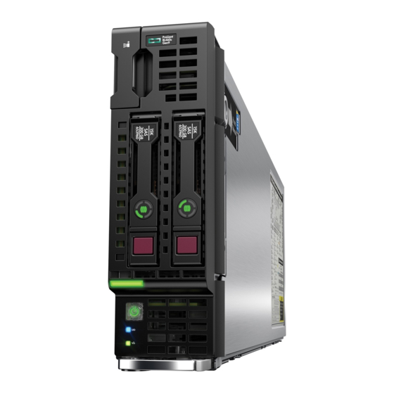
HPE ProLiant BL460c Gen9 Server
Blade
User Guide
Abstract
This document is for the person who installs, administers, and troubleshoots servers and storage systems. Hewlett Packard Enterprise
assumes you are qualified in the servicing of computer equipment and trained in recognizing hazards in products with hazardous energy
levels.
Part Number: 768826-005
March 2017
Edition: 5
Advertisement
Table of Contents

Subscribe to Our Youtube Channel
Related Manuals for HPE ProLiant BL460c Gen9


Summary of Contents for HPE ProLiant BL460c Gen9
-
Page 1: User Guide
HPE ProLiant BL460c Gen9 Server Blade User Guide Abstract This document is for the person who installs, administers, and troubleshoots servers and storage systems. Hewlett Packard Enterprise assumes you are qualified in the servicing of computer equipment and trained in recognizing hazards in products with hazardous energy levels. - Page 2 © Copyright 2014, 2017 Hewlett Packard Enterprise Development LP The information contained herein is subject to change without notice. The only warranties for Hewlett Packard Enterprise products and services are set forth in the express warranty statements accompanying such products and services. Nothing herein should be construed as constituting an additional warranty.
-
Page 3: Table Of Contents
Install the front panel/drive cage assembly ......................23 Remove the front panel/drive cage assembly ......................24 Setup ..............................25 Overview ................................25 Installing an HPE BladeSystem c-Class enclosure ....................25 Preparing the enclosure ..........................25 Installing server blade options ..........................25 Installing interconnect modules ..........................25 Interconnect bay numbering and device mapping .................. - Page 4 HPE Smart Storage Battery cabling ........................53 Direct connect SATA cabling ..........................53 Using the HPE c-Class Blade SUV Cable ......................54 Connecting locally to a server blade with video and USB devices ................. 54 Accessing a server blade with local KVM ....................54 Accessing local media devices ........................
- Page 5 System battery replacement ........................ 70 Regulatory information ......................... 72 Safety and regulatory compliance .......................... 72 Belarus Kazakhstan Russia marking ........................72 Turkey RoHS material content declaration ......................73 Ukraine RoHS material content declaration ......................73 Warranty information .............................. 73 Electrostatic discharge ......................... 74 Preventing electrostatic discharge .........................
-
Page 6: Component Identification
Component identification Front panel components Item Description Serial label pull tab HPE c-Class Blade SUV connector* (behind the serial label pull tab) Drive bay 2 Drive bay 1 Server blade release lever Server blade release button *The SUV connector and the c-Class Blade SUV Cable are used for some server blade configuration and diagnostic procedures. -
Page 7: Front Panel Leds And Buttons
Flashing red (1 flash per second) = System critical If the health LED indicates a degraded or critical state, review the system IML ("Integrated Management Log" on page 58) or use iLO ("HPE iLO" on page 57) to review the system health status. Power On/Standby... -
Page 8: Serial Label Pull Tab Information
3 flashes Memory 4 flashes Riser board PCIe slots 5 flashes FlexibleLOM 6 flashes Removable HPE Flexible Smart Array controller/Smart SAS HBA controller 7 flashes System board PCIe slots 8 flashes Power backplane or storage backplane 9 flashes Power supply For more information, see "Front panel LEDs and buttons (on page 7)."... -
Page 9: Hot-Plug Drive Led Definitions
• The drives cannot be a part of a hardware RAID or a logical drive. • The Locate, Drive status, and Do not remove LEDs of the affected drives are not controlled and will retain their last configured state. HPE SmartDrives preserve the last configured state across power cycles. -
Page 10: Nvme Ssd Components
NVMe SSD components Item Component Status Definition Release lever Ejects the NVMe drive carrier from the cage. — Activity ring LED Rotating green Drive activity No drive activity Do Not Remove Solid white Drive is powered on, and configured in system. Do not remove the drive. -
Page 11: System Board Components
System board components Item Description System battery Solid state device connector (M.2) Processor 2 DIMM slots (8) Processor 1 DIMM slots (8) SAS/SATA controller or NVMe pass-through board connector Mezzanine connector 1 (Type A mezzanine only) Mezzanine connector 2 (Type A or Type B mezzanine) Enclosure connector MicroSD card slot FlexibleLOM connectors (2) -
Page 12: Mezzanine Connector Definitions
Position Default Function Off = Power-on password is enabled. On = Power-on password is disabled. Off = No function. On = ROM reads system configuration as invalid. Off = Set default boot mode to UEFI. On = Set default boot mode to legacy. -
Page 13: Suv Cable Connectors
The arrow points to the front of the server blade. SUV cable connectors CAUTION: Before disconnecting the SUV cable from the connector, always squeeze the release buttons on the sides of the connector. Failure to do so can result in damage to the equipment. -
Page 14: Operations
For more information about the Onboard Administrator, see the enclosure setup and installation guide on the Hewlett Packard Enterprise website (http://www.hpe.com/support/BladeSystem-Enclosures-docs). For more information about iLO, see "HPE iLO (on page 57)." Power down the server blade Before powering down the server blade for any upgrade or maintenance procedures, perform a backup of critical server data and programs. -
Page 15: Remove The Server Blade
Use the Onboard Administrator GUI to initiate a shutdown: Select the Enclosure Information tab. In the Device Bays item, select the Overall checkbox. From the Virtual Power menu, initiate a shutdown of applications and the OS: — For a controlled shutdown, select Momentary Press. —... -
Page 16: Install The Access Panel
Slide the access panel towards the rear of the server blade, and then lift to remove the panel. Install the access panel Place the access panel on top of the server blade. Slide the access panel forward until it clicks into place. Remove the DIMM baffles The server contains two DIMM baffles. -
Page 17: Install The Dimm Baffles
DIMM baffle (right side) DIMM baffle (left side) Install the DIMM baffles The server contains two DIMM baffles. Power down the server blade (on page 14). Remove the server blade (on page 15). Place the server blade on a flat, level work surface. Operations 17... - Page 18 Remove the access panel (on page 15). Install the DIMM baffle. DIMM baffle (right side) DIMM baffle (left side) Install the access panel (on page 16). Install the server blade (on page 28). Power up the server blade (on page 14). Operations 18...
-
Page 19: Remove The Direct Connect Sata Cable
Remove the direct connect SATA cable Power down the server blade (on page 14). Remove the server blade (on page 15). Place the server blade on a flat, level work surface. Remove the access panel (on page 15). Remove the direct connect SATA cable. Press in the latch on the connector. -
Page 20: Remove The Mezzanine Assembly
Route and secure the cable onto the right DIMM baffle. Remove the mezzanine assembly Power down the server blade (on page 14). Remove the server blade (on page 15). Place the server blade on a flat, level work surface. Remove the access panel (on page 15). Remove the mezzanine assembly. -
Page 21: Install The Flexiblelom
Remove the access panel (on page 15). Remove the mezzanine assembly (on page 20). Use the FlexibleLOM handle to remove the FlexibleLOM from the system board. Install the FlexibleLOM Power down the server blade (on page 14). Remove the server blade (on page 15). Place the server blade on a flat, level work surface. -
Page 22: Remove The Storage Controller/Nvme Pass-Through Board
Power up the server blade (on page 14). Remove the storage controller/NVMe pass-through board Back up all server blade data. Power down the server blade (on page 14). Remove the server blade (on page 15). Place the server blade on a flat, level work surface. Remove the access panel (on page 15). -
Page 23: Remove A Drive
Remove a drive Back up all server blade data on the drive. Remove the drive. Install the front panel/drive cage assembly Power down the server blade (on page 14). Remove the server blade (on page 15). Place the server blade on a flat, level work surface. Remove the access panel (on page 15). -
Page 24: Remove The Front Panel/Drive Cage Assembly
Install the direct connect SATA cable (on page 19). Install the access panel (on page 16). Install the server blade (on page 28). Power up the server blade (on page 14). Remove the front panel/drive cage assembly Power down the server blade (on page 14). Remove the server blade (on page 15). -
Page 25: Setup
Complete the server blade configuration. Installing an HPE BladeSystem c-Class enclosure Before performing any server blade-specific procedures, install an HPE BladeSystem c-Class enclosure. The most current documentation for server blades and other BladeSystem components is available on the Hewlett Packard Enterprise website (http://www.hpe.com/support/BladeSystem-docs). -
Page 26: Interconnect Bay Numbering And Device Mapping
Interconnect bay numbering and device mapping HPE BladeSystem c7000 Enclosure To support network connections for specific signals, install an interconnect module in the bay corresponding to the FlexibleLOM or mezzanine signals. Server blade signal Interconnect Interconnect bay labels 1 and 2... -
Page 27: Connecting To The Network
HPE BladeSystem c3000 Enclosure Server blade Interconnect Interconnect Notes signal bay number bay label — FlexibleLOM Four-port cards connect to bay 2. Mezzanine 1 3 and 4 Mezzanine 2 Four-port cards Ports 1 and 3 connect to bay 3. -
Page 28: Install The Server Blade
Two types of interconnect modules are available for BladeSystem c-Class enclosures: Pass-Thru modules and switch modules. For more information about interconnect module options, see the Hewlett Packard Enterprise website (http://www.hpe.com/servers/blades/interconnects). IMPORTANT: To connect to a network with a Pass-Thru module, always connect the Pass-Thru module to a network device that supports Gigabit or 10 Gb speed, depending on the corresponding Pass-Thru model. -
Page 29: Completing The Configuration
Remove the enclosure connector cover. Retain the blank for future use. Install the server blade. Completing the configuration To complete the server blade and BladeSystem configuration, see the overview card that ships with the enclosure. Setup 29... -
Page 30: Hardware Options Installation
Hardware options installation Introduction If more than one option is being installed, read the installation instructions for all the hardware options and identify similar steps to streamline the installation process. WARNING: To reduce the risk of personal injury from hot surfaces, allow the drives and the internal system components to cool before touching them. -
Page 31: Nvme Ssd Option
Install the drive. Determine the status of the drive from the drive LED definitions ("Hot-plug drive LED definitions" on page 9). NVMe SSD option CAUTION: To prevent improper cooling and thermal damage, do not operate the server blade or the enclosure unless all drive and device bays are populated with either a component or a blank. -
Page 32: Storage Controller/Nvme Pass-Through Board Options
Determine the status of the drive from the LEDs ("NVMe SSD components" on page 10). Storage controller/NVMe pass-through board options To install the component: Back up all server blade data. Power down the server blade (on page 14). Remove the server blade (on page 15). Place the server blade on a flat, level work surface. -
Page 33: Smart Storage Battery Option
Push the handle down into the closed position to fully seat the storage controller/NVMe pass-through board. Install the access panel (on page 16). Install the server blade (on page 28). Power up the server blade (on page 14). Smart Storage Battery option To install the component: Power down the server blade (on page 14). - Page 34 Install the Smart Storage Battery on the DIMM baffle. Route the cable on the DIMM baffle. Align and install the DIMM baffle. Hardware options installation 34...
-
Page 35: Mezzanine Card Option
Press down on the cable connector to fully seat the Smart Storage Battery cable connector to the system board. If removed, install the direct connect SATA cable ("Install the direct connect SATA cable" on page 19). If removed, install the internal USB drive. To locate the internal USB connector, see "System board components (on page 11)."... - Page 36 Remove the mezzanine assembly. Align the mezzanine card with the guide pins on the mezzanine assembly. Hardware options installation 36...
-
Page 37: M.2 Enablement Option
Install the mezzanine card in the mezzanine assembly, and then tighten the mezzanine card screws to secure the card to the mezzanine assembly. Align the mezzanine assembly with the guide pins on the system board, and then install the mezzanine assembly on the system board. Press down firmly on the mezzanine assembly handles, and then close the mezzanine assembly latch. -
Page 38: Installing A Processor
Remove the access panel (on page 15). Do one of the following: Remove the storage controller/NVMe pass-through board (on page 22). Remove the direct connect SATA cable (on page 19). Remove all DIMM baffles ("Remove the DIMM baffles" on page 16). Remove the front panel/drive cage assembly (on page 24). - Page 39 Update the system ROM. Locate and download the latest ROM version from the Hewlett Packard Enterprise website (http://www.hpe.com/support). Follow the instructions on the website to update the system ROM. Power down the server blade (on page 14). Remove the server blade (on page 15).
- Page 40 Open each of the processor locking levers in the order indicated in the following illustration, and then open the processor retaining bracket. Remove the clear processor socket cover. Retain the processor socket cover for future use. CAUTION: THE PINS ON THE SYSTEM BOARD ARE VERY FRAGILE AND EASILY DAMAGED.
- Page 41 Install the processor. Verify that the processor is fully seated in the processor retaining bracket by visually inspecting the processor installation guides on either side of the processor. THE PINS ON THE SYSTEM BOARD ARE VERY FRAGILE AND EASILY DAMAGED. Close the processor retaining bracket.
-
Page 42: Memory Options
Remove the thermal interface protective cover from the heatsink. CAUTION: To avoid damage to the system board, processor socket, and screws, do not overtighten the heatsink screws. Using a T-15 screwdriver, install the heatsink. Install all DIMM baffles ("Install the DIMM baffles"... -
Page 43: Memory-Processor Compatibility Information
RDIMM, the information applies to that type only. All memory installed in the server blade must be of the same type. Memory-processor compatibility information For the latest memory configuration information, see the product QuickSpecs on the Hewlett Packard Enterprise website (http://www.hpe.com/info/qs). DIMM types Intel Xeon E5-2600 v3 processors are optimized for:... - Page 44 2400 2400 LRDIMM * HPE requires users to update the BIOS ROM to October 2016 or later versions to properly support maximum DIMM speed. Maximum memory capacity Maximum memory capacity is a function of DIMM capacity, number of installed DIMMs, memory type, and number of installed processors.
-
Page 45: Smartmemory
SmartMemory SmartMemory authenticates and unlocks certain features available only on Qualified memory and verifies whether installed memory has passed Hewlett Packard Enterprise qualification and test processes. Qualified memory is performance-tuned for ProLiant and BladeSystem servers and provides future enhanced support through Active Health and manageability software. Memory subsystem architecture The memory subsystem in this server blade is divided into channels. -
Page 46: Dimm Identification
L = LRDIMM (load reduced) For more information about product features, specifications, options, configurations, and compatibility, see the product QuickSpecs on the Hewlett Packard Enterprise website (http://www.hpe.com/info/qs). Memory configurations To optimize server blade availability, the server blade supports the following AMP modes: ... -
Page 47: General Dimm Slot Population Guidelines
AMP mode is not supported by the installed DIMM configuration, the server blade boots in Advanced ECC mode. For more information, see the HPE UEFI System Utilities User Guide for HPE ProLiant Gen9 Servers on the Hewlett Packard Enterprise website (http://www.hpe.com/info/ProLiantUEFI/docs). -
Page 48: Identifying The Processor Type
DIMMs should be populated starting farthest from the processor on each channel. For more information about server blade memory, see the Hewlett Packard Enterprise website (http://www.hpe.com/info/memory). Advanced ECC population guidelines For Advanced ECC mode configurations, observe the following guidelines: ... -
Page 49: Installing A Dimm
Installing a DIMM CAUTION: To avoid damage to the hard drives, memory, and other system components, the air baffle, drive blanks, and access panel must be installed when the server is powered up. CAUTION: To avoid damage to the hard drives, memory, and other system components, be sure to install the correct DIMM baffles for your server model. -
Page 50: Hp Trusted Platform Module Option
HP Trusted Platform Module option For more information about product features, specifications, options, configurations, and compatibility, see the product QuickSpecs on the Hewlett Packard Enterprise website (http://www.hpe.com/info/qs). Use these instructions to install and enable a TPM on a supported server blade. This procedure includes three sections: Installing the Trusted Platform Module board. - Page 51 Remove the storage controller/NVMe pass-through board (on page 22). Remove the direct connect SATA cable (on page 19). If installed, remove the internal USB drive. To locate the internal USB connector, see "System board components (on page 11)." Remove the DIMM baffle ("Remove the DIMM baffles"...
-
Page 52: Retaining The Recovery Key/Password
For more information on firmware updates and hardware procedures, see the HP Trusted Platform Module Best Practices White Paper on the Hewlett Packard Enterprise Support Center website (http://www.hpe.com/support/hpesc). For more information on adjusting TPM usage in BitLocker, see the Microsoft website (http://technet.microsoft.com/en-us/library/cc732774.aspx). -
Page 53: Cabling
Cabling configurations and requirements vary depending on the product and installed options. For more information about product features, specifications, options, configurations, and compatibility, see the product QuickSpecs on the Hewlett Packard Enterprise website (http://www.hpe.com/info/qs). HPE Smart Storage Battery cabling Direct connect SATA cabling... -
Page 54: Using The Hpe C-Class Blade Suv Cable
Using the HPE c-Class Blade SUV Cable The c-Class Blade SUV Cable enables the user to perform server blade administration, configuration, and diagnostic procedures by connecting video and USB devices directly to the server blade. For SUV cable connectors, see "SUV cable connectors (on page 13)."... -
Page 55: Accessing Local Media Devices
Item Description USB mouse USB keyboard c-Class Blade SUV Cable Accessing local media devices Use the following configuration when configuring a server blade or loading software updates and patches from a USB CD/DVD-ROM. Use a USB hub when connecting a USB CD-ROM drive to the server blade. The USB connectors on the SUV cable do not support devices that require greater than a 500mA power source. -
Page 56: Troubleshooting
Simplified Chinese (http://www.hpe.com/support/Gen9_TSG_zh_cn) The HPE ProLiant Gen9 Troubleshooting Guide, Volume II: Error Messages provides a list of error messages and information to assist with interpreting and resolving error messages on ProLiant servers and server blades. To view the guide, select a language: ... -
Page 57: Software And Configuration Utilities
QuickSpecs on the Hewlett Packard Enterprise website (http://www.hpe.com/info/qs). HPE iLO iLO is a remote server management processor embedded on the system boards of HPE ProLiant and Synergy servers. iLO enables the monitoring and controlling of servers from remote locations. HPE iLO management is a powerful tool that provides multiple ways to configure, update, monitor, and repair servers remotely. -
Page 58: Ilo Restful Api Support
(http://www.hpe.com/info/intelligentprovisioning/docs) iLO RESTful API support HPE iLO 4 firmware version 2.00 and later includes the iLO RESTful API. The iLO RESTful API is a management interface that server management tools can use to perform configuration, inventory, and monitoring of the ProLiant server via iLO. The iLO RESTful API uses basic HTTPS operations (GET, PUT, POST, DELETE, and PATCH) to submit or return JSON-formatted data with iLO web server. -
Page 59: Hpe Ilo
(http://www.hpe.com/info/insightremotesupport/docs). Insight Online HPE Insight Online is a capability of the Support Center portal. Combined with Insight Remote Support central connect or Insight Online direct connect, it automatically aggregates device health, asset, and support information with contract and warranty information, and then secures it in a single, personalized dashboard that is viewable from anywhere at any time. -
Page 60: Intelligent Provisioning
Hewlett Packard Enterprise website (http://www.hpe.com/servers/intelligentprovisioning). For consolidated drive and firmware update packages, see the Smart Update: Server Firmware and Driver Updates page on the Hewlett Packard Enterprise website (http://www.hpe.com/info/SmartUpdate). Insight Diagnostics The Insight Diagnostics is a proactive server blade management tool, available in both offline and online versions. -
Page 61: Scripting Toolkit For Windows And Linux
For more information or to download SPP, see one of the following pages on the Hewlett Packard Enterprise website: Service Pack for ProLiant download page (http://www.hpe.com/servers/spp/download) Smart Update: Server Firmware and Driver Updates page (http://www.hpe.com/info/SmartUpdate) -
Page 62: Uefi System Utilities
Provisioning For more information, see the UEFI System Utilities user guide for your product on the Hewlett Packard Enterprise website (http://www.hpe.com/info/UEFI/docs). To access mobile-ready online help for the UEFI System Utilities and UEFI Shell, scan the QR code at the bottom of the screen. -
Page 63: Flexible Boot Control
Secure Boot and have an EFI boot loader signed with one of the authorized keys can boot. For more information about supported operating systems, see the UEFI System Utilities and Shell release notes for your server blade on the Hewlett Packard Enterprise website (http://www.hpe.com/info/UEFI/docs). Software and configuration utilities 63... -
Page 64: Embedded Uefi Shell
These features enhance the capabilities of the UEFI System Utilities. For more information, see the following documents: UEFI Shell User Guide for HPE ProLiant Gen9 Servers on the Hewlett Packard Enterprise website (http://www.hpe.com/info/UEFI/docs) UEFI Shell Specification on the UEFI website (http://www.uefi.org/specifications) Embedded Diagnostics option The system BIOS in all ProLiant Gen9 servers includes an Embedded Diagnostics option in the ROM. -
Page 65: Utilities And Features
ProLiant Gen8 servers, HPE SSA replaces ACU with an enhanced GUI and additional configuration features. The HPE SSA exists in three interface formats: the HPE SSA GUI, the HPE SSA CLI, and HPE SSA Scripting. Although all formats provide support for configuration tasks, some of the advanced tasks are available in only one format. -
Page 66: Usb Support
The pre-OS behavior and default operation of the USB ports is configurable in the UEFI System Utilities. For more information, see the UEFI System Utilities user guide for your product on the Hewlett Packard Enterprise website (http://www.hpe.com/info/UEFI/docs). External USB functionality Hewlett Packard Enterprise provides external USB support to enable local connection of USB devices for server blade administration, configuration, and diagnostic procedures. -
Page 67: Keeping The System Current
SPP, see the Hewlett Packard Enterprise website (http://www.hpe.com/servers/spp/download). To locate the drivers for a particular server, go to the Hewlett Packard Enterprise Support Center website (http://www.hpe.com/support/hpesc). Under Select your HPE product, enter the product name or number and click Go. Software and firmware Update software and firmware before using the server blade for the first time, unless any installed software or components require an older version. -
Page 68: Operating Systems And Virtualization Software Support For Proliant Servers
Connect to HPE to help prevent problems and solve issues faster. By connecting, you will receive 24x7 monitoring, prefailure alerts, automatic call logging, and automatic parts dispatch. To learn more about getting connected, see the Hewlett Packard Enterprise website (http://www.hpe.com/services/getconnected). - Page 69 Let us know what Hewlett Packard Enterprise commercial products you own and we will send you the latest updates to keep your business running smoothly. For more information, see the Hewlett Packard Enterprise website (http://www.hpe.com/info/pcn). Software and configuration utilities 69...
-
Page 70: System Battery Replacement
System battery replacement If the server blade no longer automatically displays the correct date and time, then replace the battery that provides power to the real-time clock. Under normal use, battery life is 5 to 10 years. WARNING: The computer contains an internal lithium manganese dioxide, a vanadium pentoxide, or an alkaline battery pack. - Page 71 To replace the component, reverse the removal procedure. For more information about battery replacement or proper disposal, contact an authorized reseller or an authorized service provider. System battery replacement 71...
-
Page 72: Regulatory Information
Safety and regulatory compliance For important safety, environmental, and regulatory information, see Safety and Compliance Information for Server, Storage, Power, Networking, and Rack Products, available at the Hewlett Packard Enterprise website (http://www.hpe.com/support/Safety-Compliance-EnterpriseProducts). Belarus Kazakhstan Russia marking Manufacturer and Local Representative Information Manufacturer information: Hewlett Packard Enterprise Company, 3000 Hanover Street, Palo Alto, CA 94304 U.S. -
Page 73: Turkey Rohs Material Content Declaration
YYWW, where YY indicates the year, using a base year of 2000; for example, 0238: 02 for 2002 and 38 for the week of September 9. Turkey RoHS material content declaration Ukraine RoHS material content declaration Warranty information HPE ProLiant and x86 Servers and Options (http://www.hpe.com/support/ProLiantServers-Warranties) HPE Enterprise Servers (http://www.hpe.com/support/EnterpriseServers-Warranties) HPE Storage Products (http://www.hpe.com/support/Storage-Warranties) HPE Networking Products (http://www.hpe.com/support/Networking-Warranties) -
Page 74: Electrostatic Discharge
Electrostatic discharge Preventing electrostatic discharge To prevent damaging the system, be aware of the precautions you must follow when setting up the system or handling parts. A discharge of static electricity from a finger or other conductor may damage system boards or other static-sensitive devices. This type of damage may reduce the life expectancy of the device. -
Page 75: Specifications
Specifications Environmental specifications Specification Value — Temperature range* 10C to 35C (50F to 95F) Operating -30C to 60C (-22F to 140F) Non-operating — Relative humidity (noncondensing)** 10% to 90% @ 28C (82.4F) Operating 5% to 95% @ 38.7C (101.7F) Non-operating —... -
Page 76: Support And Other Resources
Hewlett Packard Enterprise Support Center. You must have an HP Passport set up with relevant entitlements. Websites Hewlett Packard Enterprise Information Library (http://www.hpe.com/info/enterprise/docs) Hewlett Packard Enterprise Support Center (http://www.hpe.com/support/hpesc) Contact Hewlett Packard Enterprise Worldwide (http://www.hpe.com/assistance) -
Page 77: Customer Self Repair
Single Point of Connectivity Knowledge (SPOCK) Storage compatibility matrix (http://www.hpe.com/storage/spock) Storage white papers and analyst reports (http://www.hpe.com/storage/whitepapers) Customer Self Repair Hewlett Packard Enterprise products are designed with many Customer Self Repair (CSR) parts to minimize repair time and allow for greater flexibility in performing defective parts replacement. If during... - Page 78 Pour plus d'informations sur le programme CSR de Hewlett Packard Enterprise, contactez votre Mainteneur Agrée local. Pour plus d'informations sur ce programme en Amérique du Nord, consultez le site Web Hewlett Packard Enterprise (http://www.hpe.com/support/selfrepair). Riparazione da parte del cliente Per abbreviare i tempi di riparazione e garantire una maggiore flessibilità nella sostituzione di parti difettose, i prodotti Hewlett Packard Enterprise sono realizzati con numerosi componenti che possono essere riparati direttamente dal cliente (CSR, Customer Self Repair).
- Page 79 Weitere Informationen über das Hewlett Packard Enterprise Customer Self Repair Programm erhalten Sie von Ihrem Servicepartner vor Ort. Informationen über das CSR-Programm in Nordamerika finden Sie auf der Hewlett Packard Enterprise Website unter (http://www.hpe.com/support/selfrepair). Reparaciones del propio cliente Los productos de Hewlett Packard Enterprise incluyen muchos componentes que el propio usuario puede reemplazar (Customer Self Repair, CSR) para minimizar el tiempo de reparación y ofrecer una mayor...
- Page 80 Packard Enterprise, póngase en contacto con su proveedor de servicios local. Si está interesado en el programa para Norteamérica, visite la página web de Hewlett Packard Enterprise CSR (http://www.hpe.com/support/selfrepair). Customer Self Repair Veel onderdelen in Hewlett Packard Enterprise producten zijn door de klant zelf te repareren, waardoor de reparatieduur tot een minimum beperkt kan blijven en de flexibiliteit in het vervangen van defecte onderdelen groter is.
- Page 81 Para obter mais informações sobre o programa de reparo feito pelo cliente da Hewlett Packard Enterprise, entre em contato com o fornecedor de serviços local. Para o programa norte-americano, visite o site da Hewlett Packard Enterprise (http://www.hpe.com/support/selfrepair). Support and other resources 81...
- Page 82 Support and other resources 82...
- Page 83 Support and other resources 83...
-
Page 84: Remote Support
Hewlett Packard Enterprise, which will initiate a fast and accurate resolution based on your product’s service level. Hewlett Packard Enterprise strongly recommends that you register your device for remote support. For more information and device support details, go to the Insight Remote Support website (http://www.hpe.com/info/insightremotesupport/docs). Support and other resources 84... -
Page 85: Acronyms And Abbreviations
Advanced Memory Protection application program interface Automatic Server Recovery certificate signing request HP SUM HP Smart Update Manager HPE SSA HPE Smart Storage Administrator Integrated Lights-Out Integrated Management Log JSON JavaScript Object Notation keyboard, video, and mouse NVMe non-volatile memory express... - Page 86 POST Power-On Self-Test RBSU ROM-Based Setup Utility REST representational state transfer serial attached SCSI Service Pack for ProLiant serial, USB, video Trusted Platform Module UEFI Unified Extensible Firmware Interface universal serial bus Version Control Agent VCRM Version Control Repository Manager Acronyms and abbreviations 86...
-
Page 87: Documentation Feedback
Hewlett Packard Enterprise is committed to providing documentation that meets your needs. To help us improve the documentation, send any errors, suggestions, or comments to Documentation Feedback (mailto:docsfeedback@hpe.com). When submitting your feedback, include the document title, part number, edition, and publication date located on the front cover of the document. For online help content, include the product name, product version, help edition, and publication date located on the legal notices page. -
Page 88: Index
Index DIMM baffles 16, 17 DIMM identification 46 DIMM installation guidelines 45, 46, 49 access panel, installing 16 DIMM population guidelines 47, 48 access panel, removing 15 DIMM slot locations 10, 12, 47 ACU (Array Configuration Utility) 65 DIMM, installing 49 Advanced ECC memory 46, 47, 48 DIMMs 10, 12, 45, 46, 49 array controllers 32... - Page 89 NIC (network interface card) 10 Hewlett Packard Enterprise, contacting 76 NVMe SSD 9, 22 HPE c-Class Blade SUV Cable 6 HPE Insight Remote Support software 58, 59, 68 HPE SmartMemory 33, 45 online spare memory 47, 48 operating systems 68...
- Page 90 SAS controller 22 VCRM (Version Control Repository Manager) 67 SAS drives 9 Version Control Agent (VCA) 67 scripted installation 61 Version Control Repository Manager (VCRM) 67 serial connector 12 video connector 12 serial label pull tab 6, 8 video devices 54 serial number 64 server blade release lever 6 server features and options 30...
Need help?
Do you have a question about the ProLiant BL460c Gen9 and is the answer not in the manual?
Questions and answers