
Related Manuals for Mira Mode


Summary of Contents for Mira Mode
- Page 1 SHOWER CONTROL Installation Operation &B Maintenance Guide THESE INSTRUCTIONS ARE TO BE LEFT WITH THE USER...
-
Page 2: Table Of Contents
INDEX Page INTRODUCTION DESCRIPTION SAFETY WARNINGS PACK CONTENTS DIMENSIONS SPECIFICATION INSTALLATION REQUIREMENTS INSTALLATION COMMISSIONING OPERATION FAULT DIAGNOSIS MAINTENANCE SPARE PARTS CUSTOMER CARE Back Cover... -
Page 3: Introduction
INTRODUCTION Thank you for purchasing a quality Mira product. To enjoy the full potential of your new product, please take time to read this guide thoroughly, having done so, keep it handy for future reference. Mira Mode Thermostatic mixing valves are specified to meet the highest standards of safety, comfort and economy as demanded by todays users. -
Page 4: Safety Warnings
SAFETY : WARNINGS Mira products are precision-engineered and should give continued superior and safe performance, provided: They are installed, commissioned, operated and maintained in accordance with the recommendations given in this Manual. Periodic attention is given, as necessary, to maintain the product in good functional order. -
Page 5: Pack Contents
PACK CONTENTS " Tick the appropriate boxes to familiarize yourself with the part names and to confirm that the parts are included. Mira Mode 1 x Valve 1 x Shower Rose 2 x Flow Regulators 1 x Support Brackets 5 x Fixing Screws 1 x Riser Arm (‘O’Seal Fitted) - Page 6 " Tick the appropriate boxes to familiarize yourself with the part names and to confirm that the parts are included. Mira Mode B 1 x Shower Arm Assembly (‘O’Seal Fitted) 1 x Shower Rose 2 x Flow Regulators 1 x Valve...
-
Page 7: Dimensions
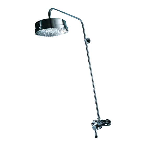
DIMENSIONS Mira Mode All dimensions are nominal and in mm 540 mm 90 mm max. 1115 mm 886 mm 110 mm... - Page 8 Mira Mode B All dimensions are nominal and in mm 477 mm 157 mm 152 mm 155 mm Dia...
-
Page 9: Specification
Suitable for use with most modulating Instantaneous Gas Water Heaters. For information on other specific applications or suitability, refer to Kohler Mira Ltd., or Local Agent. -
Page 10: Flow Rates
Operating Parameters: Pressures And Flow Rates Pressures For optimum performance, maintained supply pressures should be nominally equal. Maximum Pressure Loss Ratio: 5:1 Minimum Maintained Pressure (gravity system): 0.1 bar. (0.1 bar = 1 metre from base of cold tank to outlet of shower fitting) Maximum Maintained Pressure: 6.0 bar Minimum Maintained Pressure (gas water heater): 1.0 bar. -
Page 11: Installation Requirements
The performance specification outlined below is achieved with outlet blend temperature set between 35 - 45°C and supplies of 15°C cold and 65°C hot with nominally equal pressures. Outlet blend temperature is maintained within 2°C with a 10°C change in hot or cold supply. Thermostatic shut down to seepage within 2 seconds if cold supply fails. - Page 12 Gravity Fed System - The shower MUST be fed from a cold water cistern and hot water cylinder providing nominally equal pressure. Gas Heated System - The shower MUST be installed with a gas water heater or combination boiler of a fully modulating design. A fully modulating boiler is one where the draw off rate is indirectly controlling the gas flow to the boiler, producing a relatively constant hot water temperature.
- Page 13 Unvented Mains Pressure System - The shower can be installed with a unvented, stored hot water cylinder. Only “a competent person” as defined by the Building Regulations may fit this type of system. Mains Pressurised Instantaneous Hot Water System - The shower installed with systems of this type is supplied hot water via a tempering valve, this provides relatively constant hot water and the shower will compensate for temperature changes should they occur.
- Page 14 Pumped System - The shower can be installed with an inlet pump (twin impeller). The pump must be installed on the floor next to the hot water cylinder. Ensure hot cylinder vent pipe is arranged as shown to enable air separation. 90°...
-
Page 15: Installation
INSTALLATION General Installation must be carried out in accordance with these instructions, and must be conducted by designated, qualified and competent personnel. Before commencing, ensure that the installation conditions comply with the information given in SPECIFICATION. Care must be taken during installation to prevent any risk of injury or damage. The mixing valve should be positioned for easy access during use and maintenance. - Page 16 Regulators Two grey flow regulators are supplied with the product. They fit into the cold and/or hot inlet connectors for high pressure systems. The selection table indicates when and where these can be fitted. Optional Fitting Regulator Inlet Elbow/Connector Remove compression nut and ‘O’...
- Page 17 Mira Mode Back Inlet Supplies (rising or falling concealed pipework) Decide on a suitable position for the product ensuring that the mixer and the shower head is at a height suitable for all users to operate (Note! longer Backplate riser arms are NOT available).
- Page 18 Remove the plaster and brick/block to the required depth to conceal the pipework. Note! Depth must be sufficient to prevent pipe concealing plates fouling on the plumbing elbows. Dimension from finished wall surface Install the supply pipes. The pipes must be at 110 mm centres and project the following distances from the finished wall surface:...
- Page 19 10. Locate the shower control on to the Shower Control supply pipes and hold it in position. 11. Use a suitable spanner to tighten the nuts and pull the shower control onto the backplate. Protect the chromium plated surfaces with a cloth. Use the 2.5 mm A/F hexagon wrench (supplied) to tighten the two grub screw...
- Page 20 Shower Fittings Temporarily fit the shower arm and the support bracket to the outlet of the shower control and mark the hole Shower Arm 90 mm Maximum position. Ensure the support bracket is fitted no more than 90mm below the top of the shower arm Note! Use a spirit level or other device to ensure shower arm is vertical.
- Page 21 Mira Mode B Solid and Dry-lined Walls The built-in shower control is supplied with a support bracket (fitted) that can be used for installation into a solid or dry-lined wall structure. Installers may wish to consider other options such as fabricating rear supports using wooden noggins, however, these methods of fixing are beyond the scope of this guide.
- Page 22 Remove the plaster and brick/block 6 mm Minimum Depth for the shower control to a depth of between 76 and 93 mm from the Finished wall surface finished surface of the wall. The support bracket requires a clearance Building-in Support depth of 70 mm, with a finished wall Shroud Bracket...
- Page 23 Wall Bracket Fixing Screws 13. Fix the wall bracket to the support bracket using the four screws (supplied) and the shower control to the wall bracket, securing in position with the grub screw. Shower Control Support Bracket 2.5 mm A/F Hexagon Wrench 14.
- Page 24 18. Install the outlet pipe (ensure that the final shower head position is at a suitable height for all users). Ensure the outlet pipe will protrude 15mm from the 15 mm from the finished wall surface. wall once the finishing coat of plaster and tiles are completed.
- Page 25 26. Fit the shield assembly in place and hand tighten it to secure the concealing plate and foam seals in place. Make sure that the “Mode” logo is horizontal. 27. Fit the lever assembly and secure in position with the grub screw.
- Page 26 Fix the support bracket and shower control in position using suitable fixings (not supplied). Screw (not supplied) Note! The support bracket requires a clearance depth of 70 mm, with a finished wall thickness of 6 mm. Wall thicknesses in excess of 6 mm can be accommodated, but clearance will be required around the inlet and outlet connections to allow insertion of pipe and...
- Page 27 Back Face Installation Note! This installation is only possible with a finished wall thickness of between 4 and 21 mm, and is normally associated with the installation into laminated panels or preformed shower cubicles. 1. Decide on a suitable position for mixer where all users can operate.
- Page 28 18. Continue the procedure as for solid and dry-lined walls. 21 mm Maximum Depth Mira Mode B Shower Fittings Fit the backplate to the wall over the Ensure the backplate is fitted protruding pipe (outlet pipe from shower as illustrated.
- Page 29 Fit the ‘O’ seal over the compression nut. Fit the rigid pipe assembly over the compression nut and hand tighten the shroud onto the backplate. Rigid Pipe Assembly Backplate Shroud Fit the shower rose to the rigid pipe assembly. Rigid Pipe Assembly Shroud Shower Rose...
-
Page 30: Commissioning
The maximum blend temperature obtainable by the user should be limited, to prevent accidental selection of a temperature that is too hot. All Mira Thermostatic mixing valves are fully performance tested and the maximum temperature is preset to approximately 42 C under ideal installation conditions at the factory. -
Page 31: Operation
OPERATION Temperature Selection (Exposed/Recessed Models) The shower valve has one control to set temperature and works in a sequence: Off # # # # # Cold # # # # # # # # # # Pre-set Maximum Tepid Note! The shower performance may be degraded if other water appliances are operated whilst the shower is in use. -
Page 32: Fault Diagnosis
FAULT DIAGNOSIS Cause/Rectification Symptom Inlets reversed (hot supply to cold Only hot or cold supply). water from mixer No hot water reaching mixer. outlet. Check fittings for blockage. Installation conditions continuously outside operating parameters: refer to SPECIFICATION, and COMMISSIONING. Check fittings for blockage. Fluctuating or Make sure minimum flow rate is sufficient reduced flow rate. -
Page 33: Maintenance
MAINTENANCE General Mira products are precision-engineered and should give continued superior and safe performance, provided: They are installed, commissioned, operated and maintained in accordance with the recommendations stated in this Product Manual. Periodic attention is given as necessary to maintain the product and its associated installation components in good functional order. -
Page 34: Spare Parts
SPARE PARTS Mira Mode Spare Parts List SPHD0013J Head Assembly SPEL0003J Element SPSL0003J Sleeve Assembly SPSK0043J Seal Kit - components identified ‘A’ 441 29 Lever Assembly 441 30 Shield Assembly 441 31 Screw Pack - components identified ‘B’ 441 32... - Page 35 441 30 SPHD0013J 441 29 SPSL0003J 441 32 SPEL0003J 441 36 441 33 B (4 off) 441 34 441 35 Denotes Left Hand Thread - Turn clockwise to remove...
- Page 36 Shower Fittings Spare Parts List 441 31 Screw Pack - components identified ‘B’ 441 37 Riser Assembly 441 38 Riser Bracket Assembly 441 39 8” Rose 441 39 441 37 441 38...
- Page 37 Mira Mode B Spare Parts List 441 29 Lever Assembly 441 31 Screw Pack - components identified ‘B’ 441 36 Backplate 441 39 8” Rose 441 40 Shield Assembly 441 41 Plate Seals 441 42 Concealing Plate 441 43 Adaptor...
- Page 38 441 46 441 47 441 48 441 44 441 39 441 45 B (4 off) 441 36 441 41 441 41 441 42 441 43 441 40 441 29...
- Page 39 NOTES...
- Page 40 (2 years for Mira Select and 3 years for Mira Excel Spare Parts ranges).
Need help?
Do you have a question about the Mode and is the answer not in the manual?
Questions and answers