Table of Contents
Advertisement
Quick Links
Advertisement
Table of Contents

Related Manuals for Insportline IN 14171 Galicum


Summary of Contents for Insportline IN 14171 Galicum
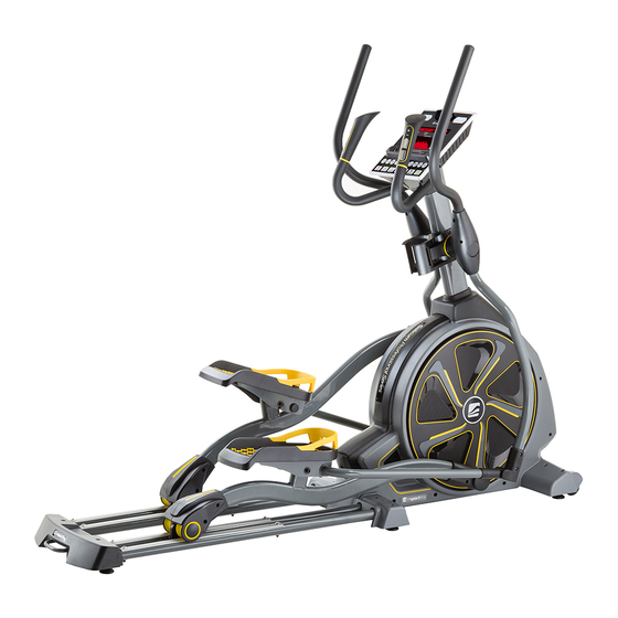
- Page 1 USER MANUAL – EN IN 14171 Elliptical Trainer inSPORTline Galicum...
-
Page 2: Table Of Contents
CONTENTS SAFETY INSTRUCTIONS ........................3 PRODUCT SPECIFICATION ........................4 ASSEMBLE PART LIST .......................... 4 OTHER COMPONENTS ......................... 6 PART LIST ............................... 7 ASSEMBLY STEPS ..........................8 EXPLODED DRAWING ......................... 17 PART LIST ............................. 18 COMPUTER OPERATION INSTRUCTIONS ..................24 BASIC INFORMATION ........................24 START WINDOWS AND STARTING .................... -
Page 3: Safety Instructions
SAFETY INSTRUCTIONS When using this product, the following basic precautions should always be followed. Please read the instructions carefully before using this product. DANGER Always unplug this product from the electrical outlet immediately after using it and also before cleaning. You will avoid the risk of an electric shock. WARNING To reduce the risk of burns, fire, electric shock or physical injury: 1. -
Page 4: Product Specification
22. Weight limit: 150 kg. 23. Category: SA (according to EN957 norm) suitable for professional and/or commercial using. 24. WARNING! The heart rate frequency monitoring may not be completely accurate. Overexertion during training can lead to a serious injury or even death. If you start to feel faint, stop the exercise immediately. - Page 5 D. Rear stabilizer E. Swing pole (L/R) F. Handrail tube (L/R) G. Pedal (L/R)
-
Page 6: Other Components
OTHER COMPONENTS Hand grip decorative H. Middle tube cover Neck cover cover K. Bent tube cover L. Post decorative cover M. Rear stabilizer N. Pedals P. Rear decorative cover Q. Screw cover R. Power supplier S. Forefoot stabilizer T. Cup holder assembly... -
Page 7: Part List
PART LIST STEP ITEM Description STEP ITEM Description CKS hex screw M10X55 Truss hex screw M8X20 Washer Ø8.5XØ30X2.0t Spring washer M10 Washer Ø10XØ30X3.0t CKS hex screw M12X35 Step5 Truss cross screw M5X10 Nylon nut M12 Step1 Washer Ø5XØ10X1.0t Carriage screw M8X45 Step6 Truss cross screw M5X10 Nylon nut M8... -
Page 8: Assembly Steps
ASSEMBLY STEPS Step. 1 – Frame and stabilizer assembly 1 Tighten the rear stabilizer (D) and the frame (A) with screws (K01), spring washers (K02) and washers (K03, K38). 2 Tighten the front stabilizer cover set (S) and the rear stabilizer cover set (M) on the frame (A) with screws (K06). - Page 9 Step 2 – Pedals and frame assembly 1. Affix the bending tube cover (K, S) onto the left fitness pedal (G-L) and tighten it with screws (K10). Then attach the left fitness pedal (G-L) to the crank shaft of the left frame and tighten it with screws (K07) and washers (K08).
- Page 10 Step 3 – Control tube and frame assembly 1 Attach the control tube (B) to the middle tube cover (H). Then please attach the control iron tube to the frame iron tube and affix the front and the sides of the iron tube with screws and washers (K11, K12, K13, K14, K15).
- Page 11 Step 4 – Control tube and computer assembly 1. Connect the wires as showed below. Pay attention to the direction and do not force them into each other. 2. Match the screw holes on back of computer (C) with the screw holes on the control tube and tighten computer with screws (K16).
- Page 12 Step 5 – Poles assembly 1. Place the washer (K18), wave washer (K19) as shown below, then attach the upper end tube of left handrail (E-L) to the iron core of the control tube and tighten it with screws (K17). 2.
- Page 13 Step 6 Swing pole and handrail tube assembly 1. Attach the end of the handrail tube (F-L) to the iron tube on the upper end of the swing pole, then tighten it with screws (K22, K23). 2. Attach the end of the handrail tube (F-R) to the iron tube on the upper end of the swing pole, then tighten it with screws (K22, K23).
- Page 14 Step 7 – Swing pole covers assembly Put the hand grip decorative cover (J) onto the hand grip tube’s rail and tighten it with screws (K24, K36). CAUTION: When you lock the plastic covers, please confirm that they match and that they are tightened enough.
- Page 15 Step 8 – Swing tube and pedal tube covers assembly 1. Match the left S bending tube cover (K) to the front end of foot pedal iron tube and tighten with screw (K37). 2. Then put the left shaft cover (L) on the left & right side of the handrail tube and match them well, then tighten with screws (K24).
- Page 16 Step 9 – Fitness pole and foot pedal assembly 1. Make the screw holes on the left foot pedal (N) match with the screw holes on the left fitness pole, then cover them with washers (K26) and tighten with screws (K25). 2.
-
Page 17: Exploded Drawing
EXPLODED DRAWING... -
Page 18: Part List
PART LIST NUMBER ITEM NUMBER ITEM Idle wheel adjust NT-3275 hook Idle wheel fixing A01 JED9-A1001 Frame assembly NT-3276 metal core Wheel belt(big) SPA060-130- Washer A02 PCT-003-2 Φ310<J10 belt use> Φ6xΦ13x1.0t C.K.S. screw A03 SGA8-20I SOC6 Nylon nut M6xP1.0 M8xP1.25x20 A04 SOC8 Nylon nut M8xP1.25 SOA6... - Page 19 A31 BJ-48-330B Belt 4.8x330mm black P-3442R Frame side cover - R Round head cross A32 BJ-22-080B Belt 2.2x80mm black SCI4-12 self-tapping screw ψ4x12 Truss cross screw A33 BJ-36-102B Belt 3.6x102mm black SCA5-10 M5xP0.8x10 Middle tube head A34 XL-1577A Battery Power Wire P-3443 cover Frame...
- Page 20 Stabilizer shaft G09 NT-3048 SOC6 Cap M6XP1.0 bushing Foam grip single BAA-0004 side tape black HED9-M1001 FOOT G11 GH-6003ZZ Bearing 6003ZZ (G) HED9-M1001 STEP IRON TUBE Foot step iron tube G12 GH-6904ZZ Bearing 6904ZZ JED9-M1001 assembly - L C.K.S. screw Foot step iron tube G13 SEC10-45I JED9-M1002...
- Page 21 Hexagonal copper SK-577 GH-63-22VV Bearing 63-22VV pillar M3x24L HED9-T1001 HED9-Q1001 (J) HED9-T1001 COMPUTER (M) HED9-Q1001 HANDRAIL TUBE CONSOLE Handrail tube P-3461 Upper computer cover JED9-Q1001 assembly - L Handrail tube P-3462 Lower computer cover JED9-Q1002 assembly - R Sound hole plastic PFA031-03- foam...
- Page 22 Grab handle Post decorative cover - P14 P-3456L P-3451R-A decorative cover right front half Grab handle Post decorative cover - P15 P-3456R P-3451R-B decorative cover right rear half P16 P-3457 Round tube end cover P-3452L Flask holder - L P17 P-3460L Neck cover - L P-3452R Flask holder - R...
- Page 23 Truss screw K07 SDA8-15IL M8XP1.25X15 blue nylon patch SPA080-250- Washer ψ8Xψ25X2.0t Truss cross screw K10 SCA5-12 M5XP0.8X12 C.K.S. screw K11 SGA8-15I M8XP1.25X15 SPA080-250- Washer ψ8Xψ25X2.0t C.K.S. screw K13 SGA10-70I M10XP1.5X70 SPA100-200- Washer ψ10Xψ20X1.0t K15 SOC10 Nylon nut M10XP1.5 Truss cross screw K16 SCA5-12 M5XP0.8X12...
-
Page 24: Computer Operation Instructions
L shaped hex wrench K29 SSA6-26-76 6 mm X 26 mm X 76 L shaped hex wrench K30 SSA5 5 mm X 25 mm X 67 m COMPUTER OPERATION INSTRUCTIONS BASIC INFORMATION This computer has a LED display and its functions are as follows: TIME, DISTANCE, RPM, HEART RATE, WORK LEVEL, WATTS, METS/PULSE, CALORIES and PROGRAM. -
Page 25: Key Function
If program is turned on but the machine stops receiving a RPM signal for 20 seconds, the program will automatically pause and show “PAUSE” on the display. If there is still no RPM signal for another 10 seconds, the system will automatically enter the standby mode. If the machine is turned on but the display and the speed sensor do not receive any input in 30 seconds, the system will automatically enter sleep mode. -
Page 26: Program Function
PROGRAM FUNCTION P1 – MANUAL MODE 1. Press the Manual key to directly enter settings, or press △ / ▽ keys to select the Manual mode, then press Enter to enter settings. 2. Weight setting: press △ / ▽ key to set the user’s weight, then press Enter to continue to the next step. -
Page 27: P5 - Hill Intervals Mode
P5 – HILL INTERVALS MODE 1. Press Hill Intervals to directly enter settings, or press △ / ▽ key to select the Hill Intervals mode and then press Enter to enter default settings. 2. Weight setting: press △ / ▽ key to set the user’s weight, then press Enter to continue to the next step. -
Page 28: P9 - User 1 Mode
6. Press Quick Start to start exercising. P9 – USER 1 MODE 1. Press User 1 to directly enter settings, or press △ / ▽ key to select the User 1 mode, then press Enter to enter default settings. 2. Weight setting: press △ / ▽ key to set the user’s weight, then press Enter to continue to the next step. -
Page 29: Profile Figure
PROFILE FIGURE BLUETOOTH COMPUTER (iOS&Android) OPERATION INSTRUCTIONS FOR iOS DEVICE (iPAD) 1. APP software download Connect the iPad to the App (iTunes) Store, search for “Pafers”, then read the APP introduction. Choose an APP to download to the iPad, for example “Tread monitor” or “Run on the Earth”. Install an APP compatible with your machine to your iPad. - Page 30 BT device matching and APP working: Step 1: Place the iPad in the area in front of the LED screen. You can attach it there. Step 2: Enter “iPad Settings program”. Step 3: Open BT and the iPad will detect all BT devices within range. Find the Treadmill BT device’s name and click on it to match them.
-
Page 31: For Android Device
FOR ANDROID DEVICE 1. APP software download Connect the Android tablet to the Play Store and search for Pafers. Then read the APP instruction. Download APP of this model into your tablet, for example “Run On Earth”. Other APP is not designed for this treadmill. - Page 32 2. BT device matching and APP operating Step 1: Place the Android device onto the area in front of the LED screen. You can attach it there. Step 2: Enter the Android device Settings Program and open BT. Step 3: Press “HOME” page button to go to the desktop. Open the APP downloaded from the Play Store.
- Page 33 Remarks: • The technology of APP function depends on the Bluetooth function and other features. Check, if the computer is equipped with BT. • After a successful matching, start the APP within 2 minutes. If it is not started within 2 minutes and the distance between the computer and tablet is more than 2 meters, the connection will automatically end.
-
Page 34: Terms And Conditions Of Warranty, Warranty Claims
iPad 2 iPad 2. Android Device: ASUS Nexus 7 Samsung Galaxy Note 2 Samsung S4 With other iOS or Android devices not included in the list, the APP can still be installed and used. Due to a different screen size, picture ratio and resolution, figures may be displayed imperfectly and calibration is required. - Page 35 Borivojova 35/878, 130 00 Praha 3, Czech Republic Headquarters: Delnicka 957, 749 01 Vitkov, Czech Republic Warranty & Service Centre: Cermenska 486, 749 01 Vitkov, Czech Republic CRN: 26847264 VAT ID: CZ26847264 Phone: +420 556 300 970 E-mail: eshop@insportline.cz reklamace@insportline.cz servis@insportline.cz...
- Page 36 Web: www.insportline.cz INSPORTLINE s.r.o. Headquarters, Warranty & Service centre: Elektricna 6471, 911 01 Trencin, Slovakia CRN: 36311723 VAT ID: SK2020177082 Phone: +421(0)326 526 701 E-mail: objednavky@insportline.sk reklamacie@insportline.sk servis@insportline.sk Web: www.insportline.sk Date of Sale: Stamp and Signature of Seller:...
Need help?
Do you have a question about the IN 14171 Galicum and is the answer not in the manual?
Questions and answers