Table of Contents
Advertisement
Quick Links
Manual F308
CAR VIEWS
CAR INFO
COOLING
UPRIGHT ASSEMBLY
SYSTEMS
GEARBOX
SAFETY AND UTILITY NOTES
TIGHTENING TORQUES
CONVERSION TABLE
GENERAL AGREEMENT
FIA Homologation document
DALLARA F308
CONTENTS
Front
VR -03
3
4
5-6
7-12
13-14
15-16
17
18
19-23
24-25
26-27
28
29
30
31
32
33
34
35
36
37-40
Advertisement
Table of Contents

Related Manuals for dallara F308


Summary of Contents for dallara F308
-
Page 1: Table Of Contents
DALLARA F308 CONTENTS Manual F308 VR -03 CAR VIEWS CAR INFO SET-UP SUSPENSION Front 7-12 Rear 13-14 DIFFERENTIAL 15-16 DAMPERS RIDE HEIGHT AERODYNAMICS 19-23 COOLING 24-25 UPRIGHT ASSEMBLY 26-27 SYSTEMS Brakes Fuel Extinguishers GEARBOX SAFETY AND UTILITY NOTES TIGHTENING TORQUES... - Page 2 DALLARA F308 DALLARA AUTOMOBILI IS HAPPY WITH THE CHOICE YOU MADE BUYING THE DALLARA F308. WE WISH YOU THE VERY BEST IN RACING IT. Dallara Automobili Via Provinciale 33 43040 VARANO MELEGARI – PR – ITALY Telephone +39 0525 550 711...
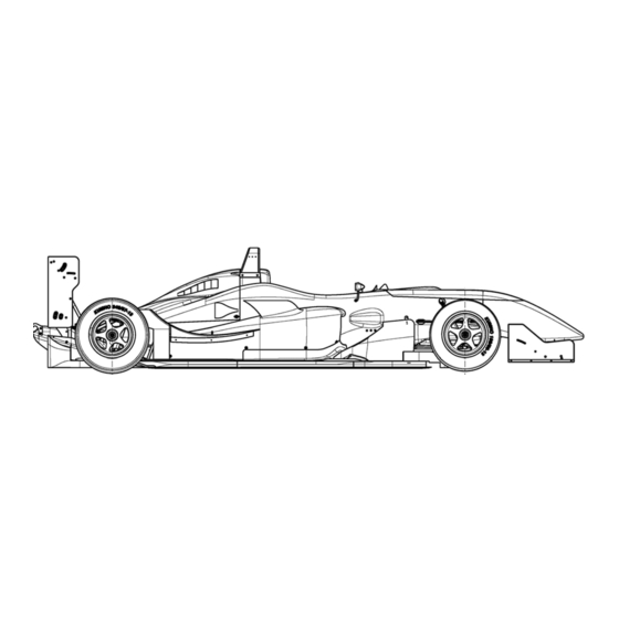
- Page 3 SIDE & TOP VIEW OF THE F308...
- Page 4 GENERAL DIMENSIONS AND SUPPLIER wheelbase 2730 mm front track 1585 mm rear track 1535 mm overall length 4264 mm overall width 1835 mm [tire-tire front] overall height 950 mm [roll hoop] weight 540 kg incl. driver & ballast front suspension pushrod twin damper system rear suspension pushrod twin damper system...
-
Page 5: Set-Up
SET-UPS PER TYRE MAKE These set-ups consider the complete car with the driver seated in it, ready to race. FRONT AVON BRIDGESTONE KUMHO DUNLOP ride height (mm) spring (Lb/in) spring pre-load the basic set-up does not suggest the use of spring pre-load pushrod length use the pushrod adjuster to set the ride height roll centre setting... -
Page 6: Set-Up
Front and rear wheel to spring, front and rear wheel to drop link motion ratios may be considered as constant for typical wheel travel. For a given ride height the F308 front roll centre is 15mm higher compared the F305. The front roll centre is adjustable by moving the spacer between the upright and the lower... - Page 7 Ks = spring stiffness in kg/m [(Ks in Lb/in) / 56 = Ks in kg/mm] T = number of spring platform turns 2 = mm / turn (for standard Dallara Koni damper top) SETTING PRE-LOAD Mount the damper-spring combination with the spring platform just in contact with...
- Page 8 FRONT CASTOR ANGLE SETTING When the car is flat, that is with the same front and rear ride height: WMP: when the upright inclination angle (apparent castor) is +2.10° the castor angle (build in castor) is 10.60°. The upright reference plane points downwards in forward direction. UMP: when the upright inclination angle (apparent castor) is -2.80°...
- Page 9 FRONT ANTI-ROLL The drawings shows both motion ratio’s STIFF SETTING SOFT SETTING The TABLE below shows the motion ratio’s for all ARB’s and different blades available. Two multiple position ARB’s are available too. RATIO = WHEEL/ARB [WHEEL vertical travel / ARB drop link travel] ADJUSTABLE BLADE ARB BLADE LENGTH SOFT...
- Page 10 FRONT ROLL BAR VALUES The values shown below are in kg/mm [daN/mm] at one end of the blade while the other end is locked. The values below are measured on the ARB isolated from the car. You may use the Motion at ground Ratio’s from page 5 to calculate the ARB stiffness On various ARB’s we suggest not to use the 115mm blade.
- Page 11 FRONT SUSPENSION TYPES The F308 car has two different options for its front suspension. WMP [Wishbone Mounted Pushrod]: This is a conventional suspension with the pushrod mounted on top of the lower wishbone. This suspension is only in detail different from the front suspension on our previous F3 car.
-
Page 12: Suspension
FRONT ROLL CENTRE SETTING and STEERING Front roll centre height can be changed by moving the spacer relative to the wishbone spherical joint. When you change to ´low roll centre´ configuration the push-rod length has to be shortened by 1.2 register turns ( ≈7 faces of the adjuster) to put the car back at the same front ride height. - Page 13 + means longer 20’ *B-2 16’ -1.0 turns 24’ *D-1 23’ -0.5 turn *E-2 18’ -1.5 turns 22’ +1.5 turns 18’ Note: B-2 needs special brackets for the front top mounting (available from Dallara). D-1 and E-2 effect the ‘caster’ angle.
- Page 14 REAR ANTIROLL BAR The F308 has rear anti-roll bars with twin adjustable blades, their length is 80mm. Ø 40mm is the biggest possible RARB, Ø13mm is the softest RARB available. The two digits in this table represent the blade positions: 1=full soft, 5=full stiff.
-
Page 15: Differential
POWER FLOW DIFFERENTIAL (Hewland) This differential is designed with versatility as its major asset. Many parameters will lead you to the required setting. A car with good grip and limited power requires a very different arrangement than that required for a high poor grip/high power car. Working principles: Ten friction plates within the diff, six connected to the side gears, four to the diff limited slip casing, control the amount of ‘differential’... -
Page 16: Differential
DIFFERENTIAL LAY-OUT (Hewland) Always use an equal friction plates arrangement on both sides. Side gear ring, diff end plate, diff wall and pre-load spacer all act as “B” plates A bigger ramp angle transmits less thrust onto the plates than a smaller ramp angle. -
Page 17: Dampers
Standard dampers are KONI 2812-899-925. Front and rear have the same dimensions and identical installation parts. Damper assembly dimensions are: full open length full closed length FRONT & REAR Stroke FRONT & REAR tighten to 55Nm 39mm 315mm DAMPER GRAPH This Koni 2812-899-925 is a damper specific for Dallara F3 cars. -
Page 18: Ride Height
RIDE HEIGHT CHECK AND REFERENCES Ride height is fundamental to setting and changing the aero balance of the car. A lower car improves performance thanks to its lower centre of gravity. The easiest way to measure the ride heights is checking the FR and RR distances between the skid block wood and the set-up floor, with the driver on board and tyres at hot tyre pressure. - Page 19 FRONT WING FRONT WING CONFIGURATIONS Note: For medium downforce settings we propose a specific front flap (more narrow than std flap); the high downforce flap is the standard flap. Both the Medium Flap and the Standard Flap are identical to those used in 2005 and 2006 [in 2007 the Gurney on the SF was modified].
- Page 20 REAR WING REARWING PROFILES These 3 profiles are given by the FIA regulations. REAR WING CONFIGURATION REAR WING SIDEPLATE _____________________...
- Page 21 15° 16° 17° 18° 19° 20° 21° 22° 23° 24° 25° F308 compared to F307 This table shows equivalent down force levels for various F307 settings compared to F308 settings. F308 F307 Rear top Lower/top Lower/top Rear top 3°/3° 3°/8°...
- Page 22 POLAR DIAGRAM F308 Balanced Polar Diagram DRAG AERO CONFIGURATIONS REAR (upper wing) FRONT (flap) LDF = Low Down Force (single small profile) MDF = Medium Down Force (twin small) MF = Medium Flap HDF = High Down Force (small and mid combined) SF = Standard Flap LDF and MDF configurations give 39% balance [% of total downforce on the front].
-
Page 23: Rear
-1° 10° REAR LOWER* 7° 18° *requests different rear wing supports, available in Dallara HOW TO KEEP THE BALANCE FOR SMALL CHANGES HOW TO BALANCE +1° FRONT FLAP BY ADJUSTING: 1. TOP REAR WING 2. REAR RIDE HEIGHT 3. FRONT RIDE HEIGHT... - Page 24 COOLING and ADJUSTMENTS Depending on the ambient temperature and the engine manufacturer requested water temperature you may need to adjust the cooling capacity of the car. The car is aerodynamically most efficient with the chimney’s closed We suggest to open the chimney’s only when extra cooling is needed.
-
Page 25: Cooling
COOLING and ADJUSTMENTS Rear Top Blanking EQUIVALENT INCREASE CONFIGURATION IN REAR HDF WING INCIDENCE 25% rear top blanking Reference +0.5° 50% rear top blanking (in order to re-balance you should reduce the rear wing incidence by 0.5°) +1° 75% rear top blanking (in order to re-balance you should reduce the rear wing incidence by 1°) -0.5°... - Page 26 HUB ASSEMBLY The following procedure explains how to change front and rear hub bearings • Removal of bearing a) Remove spigot by removing the 6 screws A; b) push off drive flange by using two 6x1 screws set on thread B; c) remove circlip C;...
- Page 27 HUB ASSEMBLY FRONT HUB REAR HUB...
-
Page 28: Oil
Check with the engine tuner for the specific amount for your engine. The drawing shows the standard engine oil tank, integrated in the gearbox main casing. Note: In combination with some engines, the Dallara F308 will not use the standard in the gearbox casing integrated oil reservoir for its engine oil. -
Page 29: Brakes
BRAKE SYSTEM BREMBO BRAKE CALIPER ASSEMBLY Note: the dark piston is the one with a bigger diameter. The car features four different callipers. TRAVEL DIRECTION BRAKE DISC ASSEMBLY 11 disc fixations to the disc bell tightening torque: 4Nm... -
Page 30: Fuel
FUEL SYSTEM F308 features single electrical-submerged high pressure fuel pump. A ‘SAFETY’ filling system with a dry-brake valve is available at Dallara. Standard system 1) filter 2) high pressure pump 3) fuel filler cap 4) breather 5) quick release valves,... -
Page 31: Extinguishers
EXTINGUISHER SYSTEM LAYOUT dashboard and external switches DETAILS The LIFELINE system is an electrically triggered Halon or foam spray fire extinguisher system. The system uses an actuator to operate the valve located on the pressurised container, containing the extinguishing liquid. These are triggered remotely using a battery powered power pack. In order to guarantee reliable operation the actuator follow military specifications. - Page 32 GEARBOX & DIFFERENTIAL GEARBOX information The F308 car mounts a Hewland 6 speed sequential gearbox, it is an updated [for 2008] version of the FTR-200. The main casing is different only in detail. Only use the specific tools to ensure proper maintenance. Hewland has written a technical manual, including a spare parts list, for the FTR-200.
- Page 33 Do not drill any new mounting holes further up the column than the upper holes standard made by Dallara. Any new fixation holes should always be between the lower and upper holes, standard in the column. SUSPENSION Regularly check wheel stud to inner hub tightening in front and rear uprights.
- Page 34 SUSPENSION Ball-joint A, used in the front lower and rear lower wishbones, must be fitted with sharp-edge side in contact with circlip B, as shown in following drawing. For the front lower wishbone this is only the case on the WMP suspension type. TIGHTENING TORQUES This table lists suggested tightening torques.
- Page 35 SWG & CONVERSION TABLES Table shows conversion from SWG (Std Wire Gage) to metric units for sheet-metal thickness Metric (mm) 4.064 3.251 2.642 2.032 1.626 1.219 0.914 CONVERSION TABLE Length 1 inch=25.4 mm 1 millimetre=0.03937 in 1 foot=304.8 mm=12 in 1 centimetre=0.3937 in 1 yard=914.4 mm=3 ft 1 meter=39.37 in...
- Page 36 25,000km. It holds true if necessary maintenance and checks are provided and if the car had no incidents from the origin. DALLARA is not responsible for incorrect chassis repairs, if made outside its factory or in centres not- recognised by FIA.
- Page 37 2008 F3 STRUCTURE TESTING RECORD Constructor : Dallara Chassis type : 308 Chassis number : 11 Date : 1 – 3/10/07, 18/01/08 Place : Dallara, CSI, Politechnico Present : G. Consonni, N. Concari, F. Grippa, G. Forbes Test 3 1880...
- Page 38 Chassis number : 308 - 11 Test 2a : An impact test against a solid barrier at 10 metres/sec with a total mass of 560kg Impact speed : 10.09 Deformation : Deceleration Peak : 39.05 g Mean : 23.37 g Structure fixings : 2 x 2 M8 laterally + 2 x M8 on top bolted to gearbox end cap Structure weight : 1.539 Comments...
- Page 39 1139 Test 3 Rear impact structure Gearbox assembly Rear wheel centre line Rear face of the engine Test 3 : A 83.55kN or 66.84kN load applied at a compound angle to the top of the main roll structure Load 83.8 kN Displacement 9.37 mm ( 7.86 mm) Difference 100 %...
- Page 40 Chassis number : 308 - 11 Test 10 : A 10.00kN or 8kN load applied in 3 mins to the cockpit rims and held for 30 secs Load 10.0 kN Displacement 2.84 mm ( 2.13 mm) Difference 100 % Deformation 0.20 mm Comments : OK.
Need help?
Do you have a question about the F308 and is the answer not in the manual?
Questions and answers