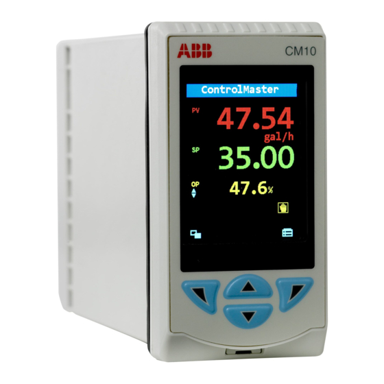
ABB ControlMaster CM10 User Manual
Universal process controllers
Hide thumbs
Also See for ControlMaster CM10:
- User manual (91 pages) ,
- Manual (34 pages) ,
- Communications supplement (30 pages)
Table of Contents
Advertisement
User Guide – Standard Functionality IM/CM/S–EN Rev. R
ControlMaster CM10, CM30 and CM50
Universal process controllers,
1
/
,
1
/
and
1
/
DIN
8
4
2
The Company
We are an established world force in the design and manufacture of instrumentation for industrial process control,
flow measurement, gas and liquid analysis and environmental applications.
As a part of ABB, a world leader in process automation technology, we offer customers application expertise, service
and support worldwide.
We are committed to teamwork, high quality manufacturing, advanced technology and unrivalled service and
support.
The quality, accuracy and performance of the Company's products result from over 100 years experience, combined
with a continuous program of innovative design and development to incorporate the latest technology.
Advertisement
Table of Contents

Related Manuals for ABB ControlMaster CM10


Summary of Contents for ABB ControlMaster CM10
- Page 1 User Guide – Standard Functionality IM/CM/S–EN Rev. R flow measurement, gas and liquid analysis and environmental applications. ControlMaster CM10, CM30 and CM50 As a part of ABB, a world leader in process automation technology, we offer customers application expertise, service Universal process controllers, and support worldwide.
- Page 2 Refer to Section 6, page 27 Refer to Section 7.1, page 36 Refer to Section 7.2, page 39 Refer to Section 7.3, page 43 Refer to Section 7.4, page 51 Menu Menu Menu Menu Menu Basic Device Setup Display Input/Output Control Back Cover...
-
Page 3: Table Of Contents
ControlMaster CM10, CM30 and CM50 Universal process controllers, Contents Contents 1 Safety ................3 4 Installation ..............8 1.1 Electrical Safety ............. 3 4.1 Siting and Environmental Requirements ....8 1.2 Symbols ..............3 4.2 Dimensions ............9 1.3 Health & Safety ............. 4 4.3 Mounting ............. - Page 4 ControlMaster CM10, CM30 and CM50 Universal process controllers, Contents 7 Advanced Level ............36 9 PC Configuration .............107 7.1 Device Setup ............36 10 Specification ............108 7.2 Display ..............39 7.3 Input/Output ............43 Appendix A – Digital and Analog Sources ....116 7.4 Control ..............
-
Page 5: And
ControlMaster CM10, CM30 and CM50 Universal process controllers, 1 Safety 1 Safety 1.2 Symbols One or more of the following symbols may appear on the Information in this manual is intended only to assist our equipment labelling: customers in the efficient operation of our equipment. Use of... -
Page 6: Health & Safety
ControlMaster CM10, CM30 and CM50 Universal process controllers, 2 Introduction 1.3 Health & Safety 2 Introduction This manual provides details for the ControlMaster CM10 ( DIN), CM30 ( DIN) and CM50 ( DIN) Health and Safety controllers with Standard functionality. -
Page 7: Displays, Icons And Keys
Advanced Level (see page 36) must be accessed using the Operator Level access key A. Alarm Icons Remote Setpoint Status Access Local Setpoint Level Operator Manual Control Level Mode Auto Control Mode Fig. 3.1 ControlMaster CM10 Display and Icons IM/CM/S–EN Rev. R... -
Page 8: Cm30 And Cm50 Operator Page, Icons & Keys
ControlMaster CM10, CM30 and CM50 Universal process controllers, 3 Displays, Icons and Keys 3.2 CM30 and CM50 Operator Page, Icons & Keys The ControlMaster CM30 and CM50 displays and icons are shown in Fig. 3.2. Icons Access Autotune Local Setpoint... - Page 9 ControlMaster CM10, CM30 and CM50 Universal process controllers, 3 Displays, Icons and Keys The ControlMaster CM30 and CM50 front panel keys are shown in Fig. 3.3. Navigation (left) / Operator Level access key – see page 22. Local / Remote setpoint mode selection key.
-
Page 10: Installation
ControlMaster CM10, CM30 and CM50 Universal process controllers, 4 Installation 4 Installation 4.1 Siting and Environmental Requirements CM30 CM30 CM30 Sensor At Eye Level Close to the Sensor Avoid Vibration IP66/NEMA4X (front panel) IP20 (rear) 55°C 0 to 95% RH... -
Page 11: Dimensions
CM30 91.8 (3.81) (3.6) 141 (5.55) +0.02 +0.6 +0.8 +0.03 (1.77) –0 –0 –0 (3.62) –0 Panel Cut-out +0.8 –0 Dimensions +0.03 –0 (3.62) 30 (1.18) 14 (0.55) 14 (0.55) Fig. 4.2 ControlMaster CM10 and CM30 Dimensions IM/CM/S–EN Rev. R... - Page 12 ControlMaster CM10, CM30 and CM50 Universal process controllers, 4 Installation Dimensions in mm (in.) 23 (0.9) 123 (4.84) 76 (3.0) (5.67) (5.43) 146 (5.74) +0.7 –0 (2.67 +0.03 –0 Controllers can be +1.0 –0 close-stacked to (5.43) (+0.04 –0) DIN 43835 30 (1.18)
-
Page 13: Mounting
ControlMaster CM10, CM30 and CM50 Universal process controllers, 4 Installation 4.3 Mounting ControlMaster is designed for panel mounting. For NEMA4X protection, a panel thickness of 2.5 mm (0.1 in.) is required. To panel-mount the controller: Cut a hole of the correct size for the controller in the panel –... -
Page 14: Jumper Links For Relay Outputs
ControlMaster CM10, CM30 and CM50 Universal process controllers, 4 Installation 4.4 Jumper Links for Relay Outputs The factory-set default for relay action is N/O. 4.4.1 Removing the Controller from its Case The ControlMaster inner assembly must be removed from its case to access the relay contact jumper links. -
Page 15: Resetting Jumper Links
ControlMaster CM10, CM30 and CM50 Universal process controllers, 4 Installation 4.4.2 Resetting Jumper Links CM10 and CM30 Note. The factory-set default for all jumper links is N/O. Option Board 1 / 1a 1. The links associated with the relay outputs are shown in Fig. -
Page 16: Electrical Connections
ControlMaster CM10, CM30 and CM50 Universal process controllers, 4 Installation 4.5 Electrical Connections Warning. The controller is not fitted with a switch therefore a disconnecting device such as a switch or circuit breaker conforming to local safety standards must be fitted to the final installation. -
Page 17: Cm10 Electrical Connections
*** 200 mA Type T fuse (mains AC) or 2 A Type T fuse (120 V DC max.) and external Relay isolating switch. For UL-marked controllers the fuse must be UL recognized Output 2 **** Provides 24 V digital output (observe + and – connections) Fig. 4.7 ControlMaster CM10 Electrical Connections IM/CM/S–EN Rev. R... -
Page 18: Cm30 Electrical Connections
ControlMaster CM10, CM30 and CM50 Universal process controllers, 4 Installation 4.5.2 CM30 Electrical Connections Rear Rear Rear View View View Standard Connections Option Board 1 Option Board 2 Analog Output 2 – Analog Analog Input 3 Digital Output + External Input 1 –... -
Page 19: Cm50 Electrical Connections
ControlMaster CM10, CM30 and CM50 Universal process controllers, 4 Installation 4.5.3 CM50 Electrical Connections Rear View Rear View Option Board 1 Standard Connections Analog Input 3 Analog Input 1 – – Analog Input 2 Analog Input 4 – – *Refer to rear panel for –... -
Page 20: Analog Inputs
ControlMaster CM10, CM30 and CM50 Universal process controllers, 4 Installation 4.5.4 Analog Inputs 2-lead RTD + Resistance 3-lead RTD RTD – 3rd lead Milliamps* RTD + RTD + Analog Input 1 **** Digital Input CJ** RTD – RTD – Milliamps*... - Page 21 ControlMaster CM10, CM30 and CM50 Universal process controllers, 4 Installation 2-lead RTD CM30 CM50 3-lead RTD + Resistance 3rd lead RTD – Milliamps* RTD + Analog RTD + **** Input 3 Digital Input CJ** RTD – RTD – Milliamps* mA, mV, V,...
-
Page 22: Frequency / Pulse Input
ControlMaster CM10, CM30 and CM50 Universal process controllers, 4 Installation 4.5.5 Frequency / Pulse Input Note. This input is designed primarily for use with flowmeters. External Voltage (Max. 30 V) Source Device ControlMaster –ve Load* Terminal 1 Input 1 Terminal 3... - Page 23 ControlMaster CM10, CM30 and CM50 Universal process controllers, 4 Installation Terminal Connections on Standard and Option Boards Digital Input/Output + External CM10: Terminal 21 CM30: Terminal 43 or 35 CM50: Terminal 7 or 30 Load Digital Input/Output CM10: Terminal 22 or 23 External Voltage CM30: Terminal 44 or 45;...
-
Page 24: Operator Level Menus
ControlMaster CM10, CM30 and CM50 Universal process controllers, 5 Operator Level Menus 5 Operator Level Menus Operator level menus are used to adjust setpoint(s) and output(s), select setpoints, select the view and to enter Basic and Advanced modes (via the Access level). - Page 25 ControlMaster CM10, CM30 and CM50 Universal process controllers, 5 Operator Level Menus Autotune Used to start or stop an autotune routine. This menu is enabled only if Autotune mode is On – see page 29. Adjust Enables a value to be adjusted using the keys.
-
Page 26: Diagnostic Status Bar
ControlMaster CM10, CM30 and CM50 Universal process controllers, 5 Operator Level Menus 5.1 Diagnostic Status Bar PV 1 Failed ControlMaster 99.5 deg C NAMUR (NE107) Status Icon Description of diagnostic 175.0 or alarm tag. Failure High Process Alarm The highest priority diagnostic or 32.5... -
Page 27: Diagnostic View
ControlMaster CM10, CM30 and CM50 Universal process controllers, 5 Operator Level Menus 5.2 Diagnostic View 5.3 Security Options The Diagnostic View can be selected from the Operator / Passwords can be set to enable secure end-user access at View Select menu. All currently active diagnostic alarm states 2 levels: Basic and Advanced The Service level is password- are displayed in the Diagnostic View. -
Page 28: Access Level
ControlMaster CM10, CM30 and CM50 Universal process controllers, 5 Operator Level Menus 5.4 Access Level Level Access To view Access Level ControlMaster Access Level Logout Displayed after levels are Basic Advanced 27.589 accessed. Logs the user out of Basic or Logout level. -
Page 29: Basic Level
ControlMaster CM10, CM30 and CM50 Universal process controllers, 6 Basic Level 6 Basic Level Menu The Basic menu provides access to the tunable control settings and setpoint values. Basic Loop 1 Setpoints Local Setpoint 1 (4) The local setpoint value required. If this value is adjusted in the Operator Level (see page 22) its value here is also updated. - Page 30 ControlMaster CM10, CM30 and CM50 Universal process controllers, 6 Basic Level …Basic / …Loop 1 Setpoints Ramp Mode The ramping setpoint facility can be Displayed local setpoint value used to prevent a large disturbance to the control output when the setpoint value is changed.
- Page 31 ControlMaster CM10, CM30 and CM50 Universal process controllers, 6 Basic Level …Basic / …Loop 1 Control Mode Turns the Autotune functionality on or off. When set to On, an Autotune can be started from the Operator level menus – see page 22.
- Page 32 ControlMaster CM10, CM30 and CM50 Universal process controllers, 6 Basic Level …Basic / …Loop 1 Control / …Autotune First Step Defines the maximum size of the first output step in the autotuning process. Autotune adjusts the output step magnitude according to the process noise and response to provide a reliable measurement of the process characteristics with the minimum disturbance of the process.
- Page 33 ControlMaster CM10, CM30 and CM50 Universal process controllers, 6 Basic Level …Basic / …Loop 1 Control / …PID Derivative Time 1 Set in seconds. Manual Reset When the Integral Time is Off, the manual reset parameter is activated. When the process variable is equal to the control setpoint, the output value is equal to the manual reset value.
-
Page 34: And
ControlMaster CM10, CM30 and CM50 Universal process controllers, 6 Basic Level …Basic Loop 1 Mot Valve Example of Motorized Valve With Feedback Open Relay Motorized Valve (OP x Ratio) + Bias Controller Close Relay Position Feedback Motorized Valve Output Without Feedback (Boundless) - Page 35 ControlMaster CM10, CM30 and CM50 Universal process controllers, 6 Basic Level …Basic / …Loop 1 Mot Valve Calculation for Control Pulses (Boundless Control) The following calculations are for guidance when setting Deadband, proportional and integral values. The Deadband on the ControlMaster is set in engineering units, but in order to be applied to the calculations it must be set...
- Page 36 ControlMaster CM10, CM30 and CM50 Universal process controllers, 6 Basic Level …Basic / …Loop 1 Mot Valve Deadband Example: If the valve is set to be driven to the 50 % open position and the deadband is set to 4 %, the motor stops driving when the position feedback is 48 %. The deadband is between 48 % and 52 %.
- Page 37 ControlMaster CM10, CM30 and CM50 Universal process controllers, 6 Basic Level …Basic Loop 1 Time Prop The active time of the output pulse is proportional to the value of the control output. With 100% output the pulse is active for the complete cycle time, for example: Note.
-
Page 38: Advanced Level
ControlMaster CM10, CM30 and CM50 Universal process controllers, 7 Advanced Level 7 Advanced Level 7.1 Device Setup Provides access to standard setup parameters to determine the type of control / indication required. Also Menu Device Setup provides the ability to create non-standard configurations for special application requirements. - Page 39 ControlMaster CM10, CM30 and CM50 Universal process controllers, 7 Advanced Level …Device Setup / …Initial Setup Instrument Tag A 16-character alphanumeric tag, displayed on Operator pages. Mains Freq Used to set the internal filters to reduce mains power frequency interference.
- Page 40 ControlMaster CM10, CM30 and CM50 Universal process controllers, 7 Advanced Level …Device Setup Security Setup 2 Security access levels are provided, each protected by a password of up to 6 alphanumeric characters. Note. Passwords are not set at the factory and must be entered by the end user(s).
-
Page 41: Display
ControlMaster CM10, CM30 and CM50 Universal process controllers, 7 Advanced Level 7.2 Display Used to setup the operator page, displayed language and display hardware settings. Menu Display Language Selects the language on the controller's local display. Operator Templates Enables up to 4 operator pages to be configured to suit the application requirements. - Page 42 ControlMaster CM10, CM30 and CM50 Universal process controllers, 7 Advanced Level …Display Operator Functions Autoscroll When enabled (On), operator pages are scrolled continuously at intervals of 10 seconds per page. Soft Key Function Assigns a dedicated function to the Navigation key (right) – see page 5.
- Page 43 ControlMaster CM10, CM30 and CM50 Universal process controllers, 7 Advanced Level …Display / …Operator Functions Auto Manual Enable Turns on / off the ability for Auto and Manual control mode to be changed in Operator Level. Local Remote Enable Turns on / off the ability for Local and Remote setpoint mode to be changed in Operator Level.
- Page 44 ControlMaster CM10, CM30 and CM50 Universal process controllers, 7 Advanced Level …Display / …Date & Time / …Daylight Saving DS Region Daylight saving is disabled. Europe Standard daylight saving start and end times are selected for Europe automatically. Standard daylight saving start and end times are selected for USA automatically.
-
Page 45: Input/Output
ControlMaster CM10, CM30 and CM50 Universal process controllers, 7 Advanced Level 7.3 Input/Output Enables analog and digital inputs / outputs and relays to be configured. Menu Input/Output Analog Inputs Analog Input 1 (4)* Millivolts, Milliamps, Volts, Resistance (Ohms), RTD, Thermocouple, Digital... - Page 46 ControlMaster CM10, CM30 and CM50 Universal process controllers, 7 Advanced Level … Input/Output / …Analog Input 1 (4) Elect. Low Sets the required electrical range. Note. Applicable only to Millivolts, Milliamps, Volts and Ohms. Linear Inputs Standard Analog Input Accuracy (% of Reading)
- Page 47 ControlMaster CM10, CM30 and CM50 Universal process controllers, 7 Advanced Level … Input/Output / …Analog Input 1 (4) Eng Units The selected units are used by the linearizer and displayed in the Operator pages. Not applicable for: Pulse Input, Volt Free Digital, 24Volt Digital parameters.
- Page 48 ControlMaster CM10, CM30 and CM50 Universal process controllers, 7 Advanced Level … Input/Output / …Analog Input 1 (4) Pulse Units Selects the unit of measure for the pulse input type. Pulse / Unit Sets the number of pulses required to represent 1 pulse unit (as set above), for example, if Pulse Units = Kl and Pulse / Unit = 10.00000000, each pulse represents 0.1 Kl,...
- Page 49 ControlMaster CM10, CM30 and CM50 Universal process controllers, 7 Advanced Level …Input/Output / … …Analog Input 1 (4) Filter Time The input is averaged over the time set. Fault Detect Sets a tolerance level (in % of engineering range) to allow for deviation of the input signal above or below the engineering range before an input failure is detected.
- Page 50 ControlMaster CM10, CM30 and CM50 Universal process controllers, 7 Advanced Level …Input/Output / … …Analog Outputs Elect. Low* The current output required when the source value is equal to the Eng Low value – see page Elect. High* The current output required when the source value is equal to the Eng High value – see page...
- Page 51 ControlMaster CM10, CM30 and CM50 Universal process controllers, 7 Advanced Level …Input/Output Digital I/O Digital IO 1 (6) Type Sets the Digital IO to operate as an output or an input. No action taken. Output The Digital IO operates as an output.
- Page 52 ControlMaster CM10, CM30 and CM50 Universal process controllers, 7 Advanced Level …Input/Output Relays Relay 1 (4) Source Selects the digital signal to be assigned to the relay – see Appendix A.1, page 116 for description of sources. Polarity Sets the polarity of the relay.
-
Page 53: Control
ControlMaster CM10, CM30 and CM50 Universal process controllers, 7 Advanced Level 7.4 Control Enables the setpoints, control functions and outputs to be configured. Menu Control Loop 1 Setpoints The controller can configure independent local setpoint values, remote setpoint functionality and limit the absolute values and rate of change of the control setpoint. - Page 54 ControlMaster CM10, CM30 and CM50 Universal process controllers, 7 Advanced Level …Control / …Loop 1 Setpoints Track Mode The local (internal) setpoint can track another value according to the setpoint tracking mode selected. No tracking. Local The local (internal) setpoint tracks the process variable when Manual control mode is selected.
- Page 55 ControlMaster CM10, CM30 and CM50 Universal process controllers, 7 Advanced Level …Control / …Loop 1 Setpoints RSP Fault Action The action required when a fault occurs with the remote setpoint. No Action No fault action. Local Selects the local (internal) setpoint mode.
- Page 56 ControlMaster CM10, CM30 and CM50 Universal process controllers, 7 Advanced Level …Control / …Loop 1 Setpoints / Select Sources LSP1 (4) Select The source required to select local setpoint 1 (LSP1) as the current LSP1 local setpoint. Selection is made on the rising edge of the digital signal.
- Page 57 ControlMaster CM10, CM30 and CM50 Universal process controllers, 7 Advanced Level …Control Loop 1 Control Configures the basic type of control required and the PID (see page 30) and Autotune (see page 29) settings. Control Type Selects the basic type of controller required.
- Page 58 ControlMaster CM10, CM30 and CM50 Universal process controllers, 7 Advanced Level …Control Loop 1 Output Used to set the output limits, tracking rates, slew rates and output action on power failure or process variable failure. Limits Note. When used with split output the limits restrict the PID algorithm output (see page 30) before the split output range values are calculated.
- Page 59 ControlMaster CM10, CM30 and CM50 Universal process controllers, 7 Advanced Level …Control / …Loop 1 Output / …Failure Actions / …Power Recovery Man – Default Manual control mode with output set to default value. Auto Mode Auto control mode with integral term reset.
- Page 60 ControlMaster CM10, CM30 and CM50 Universal process controllers, 7 Advanced Level …Control / …Loop 1 Output A/M Select Sources The selection of A/M (Auto / Manual) control modes of operation can be controlled by digital signals; either from internal digital signals (for example, alarm states) or from external signals via digital inputs (or digital communications).
- Page 61 ControlMaster CM10, CM30 and CM50 Universal process controllers, 7 Advanced Level …Control / …Loop 1 Output Manual 1 (2) Used when Manual 1 (2) Output is set to Config Value. Config O/P A/M Toggle The source required to toggle between A/M (Auto / Manual) control Manual modes.
- Page 62 ControlMaster CM10, CM30 and CM50 Universal process controllers, 7 Advanced Level …Control / …Loop 1 Output Slew Rate The (output) Slew Rate restricts the maximum rate of change of the control output. Function Selects if the output Slew Rate function is enabled and when it applies.
- Page 63 ControlMaster CM10, CM30 and CM50 Universal process controllers, 7 Advanced Level …Control /…Loop 1 Output Tracking Configures the control output follow a tracking signal when in Auto control mode. In Manual control mode, the output can be adjusted as normal. If the Slew Rate (see page 60) function is enabled, switching from Manual to Auto is bumpless.
- Page 64 ControlMaster CM10, CM30 and CM50 Universal process controllers, 7 Advanced Level …Control Loop 1 Split O/P* The split output facility enables the PID control output (see page 30) to be split into 2 separate outputs. This enables heat / cool and other applications requiring dual outputs to be controlled. The linear relationship between the input from the PID algorithm and the 2 outputs is configured using the Min and Max Input / Output parameters (see below).
-
Page 65: Process Alarm
ControlMaster CM10, CM30 and CM50 Universal process controllers, 7 Advanced Level 7.5 Process Alarm Used to configure up to 8 independent process alarms. Menu Process Alarm Process Alarm Hysteresis Trip point Hysteresis Process Variable Alarm On High Process Alarm Off... - Page 66 ControlMaster CM10, CM30 and CM50 Universal process controllers, 7 Advanced Level …Process Alarm Process Variable Trip Trip Point Hysteresis Point Hysteresis Process Variable Alarm Latched Alarm On Alarm On Alarm Latched Alarm Alarm Alarm Acknowledged by Operator Alarm Acknowledged by Operator...
- Page 67 ControlMaster CM10, CM30 and CM50 Universal process controllers, 7 Advanced Level …Process Alarm / … Alarm 1 (8) Hysteresis Hysteresis trip level in engineering units. Activated at the alarm trip level but deactivated only when the process variable has moved into the safe region by an amount equal to the hysteresis value –...
-
Page 68: Profile
ControlMaster CM10, CM30 and CM50 Universal process controllers, 7 Advanced Level 7.6 Profile facility is a setpoint profile generator which can be used with any type Ramp Soak Profile Menu Profile of control process for more complex setpoint control. A... -
Page 69: Ramp Types
ControlMaster CM10, CM30 and CM50 Universal process controllers, 7 Advanced Level 7.6.1 Ramp Types The profile set point can be configured to increment in one of two-way: for a fixed period of time or for a number of engineering units per hour. -
Page 70: Guaranteed Ramp / Soak
ControlMaster CM10, CM30 and CM50 Universal process controllers, 7 Advanced Level 7.6.2 Guaranteed Ramp / Soak If the process variable deviates from the set point by more than the hysteresis value, the program status is set to HOLD and Guaranteed ramp/soak is applied automatically. - Page 71 ControlMaster CM10, CM30 and CM50 Universal process controllers, 7 Advanced Level Hysteresis applied Hi-Lo Skip forward (above and below the set point) Adjustable ramp rates Manual pause Hysteresis applied Hi (above the set point) Adjustable holdback hysteresis 1. for Ramp segments End of profile (revert to 2.
-
Page 72: Set Point Start Condition - Current Pv
ControlMaster CM10, CM30 and CM50 Universal process controllers, 7 Advanced Level 7.6.3 Set Point Start Condition – Current PV Selecting Current PV reduces the delay between the end of a program and the beginning of the next program. The process variable value is used as the program start point and the set point steps up to the process variable value. -
Page 73: Profile Parameters
ControlMaster CM10, CM30 and CM50 Universal process controllers, 7 Advanced Level 7.6.4 Profile Parameters Common Settings SPT Start Condition A start condition shall be specified for each control loop that determines the initial start setpoint of the program. Program Setpoint The program will start at the setpoint configured by Setpoint Start parameter. - Page 74 ControlMaster CM10, CM30 and CM50 Universal process controllers, 7 Advanced Level …Profile Parameters / …Common Settings Ramp Control Ramp Type Selects the Ramp Type required. The ramp type selected applies to all programs / segments. The profile set point can be configured to increment in one of two way: for a fixed period of time or for a number of engineering units per hour.
- Page 75 ControlMaster CM10, CM30 and CM50 Universal process controllers, 7 Advanced Level …Profile Parameters / …Common Settings / …Program Control Reset Selects the digital source used to reset a running program. The program is reset on a rising edge. If the program was running, it will run from the start. If the program was held it will remain held at the start point.
- Page 76 ControlMaster CM10, CM30 and CM50 Universal process controllers, 7 Advanced Level …Profile Parameters / …Common Settings / …Program Control Recovery Action Selects the profile restart action when power is restored after a failure or the PV is restored after a failure and the Recovery Period (Time – see below) has expired.
- Page 77 ControlMaster CM10, CM30 and CM50 Universal process controllers, 7 Advanced Level …Profile Parameters / …Common Settings / …Segment Options Segment Options G'teed Ramp/ Enables the Guaranteed Ramp/Soak (Holdback) function. When enabled (On), the relevant Soak configuration frames are displayed in Program / Segment menus to allow the Guaranteed Ramp/ Soak function to be configured.
- Page 78 ControlMaster CM10, CM30 and CM50 Universal process controllers, 7 Advanced Level …Profile Parameters / …Enter Program Setpoint Start/End Start The start setpoint value for the first segment of the program. Note. Available only if the SPT Start Condition parameter is set to Program Setpoint.
- Page 79 ControlMaster CM10, CM30 and CM50 Universal process controllers, 7 Advanced Level …Profile Parameters / …Enter Program Enter Segments Segment No. Enter the segment number to be configured. Type Select the segment type as described below: Soak Maintains the setpoint at a constant value for the duration of the segment.
- Page 80 ControlMaster CM10, CM30 and CM50 Universal process controllers, 7 Advanced Level …Profile Parameters / …Enter Program / …Enter Segments Ramp Time Increases or decreases the setpoint at a linear rate until the desired value is reached ( (if Ramp Type = Time .
- Page 81 ControlMaster CM10, CM30 and CM50 Universal process controllers, 7 Advanced Level …Profile Parameters / …Enter Program / …Enter Segments Guaranteed Ramp Select how the Guaranteed Ramp/Soak feature will be applied to the segment. Guaranteed Soak None Guaranteed Ramp/Soak is disabled for the segment.
-
Page 82: Functions
ControlMaster CM10, CM30 and CM50 Universal process controllers, 7 Advanced Level 7.7 Functions Contains parameters for setting up the math block(s), logic equations and timer functions within the Menu Functions controller. Logic Equations Up to 8 logic equations can be configured. Each can combine up to 8 operands (digital signals) with 7 operators. - Page 83 ControlMaster CM10, CM30 and CM50 Universal process controllers, 7 Advanced Level …Functions / Logic Equations Equation Number Selects the logic equation (1 to 8) to be configured. Operand 1 (8) See Appendix A, page 116 for description of sources. Invert 1 (8) Logically inverts (applies NOT function to) the digital signal.
- Page 84 ControlMaster CM10, CM30 and CM50 Universal process controllers, 7 Advanced Level …Functions / …Math Blocks / …Block Type Equation Enables an equation with up to 4 operands and 3 operators to be created. The operands can be assigned to any analog or digital signal (see Appendix A, page 116). Digital signals have value of either '0' or '1'.
- Page 85 ControlMaster CM10, CM30 and CM50 Universal process controllers, 7 Advanced Level …Functions / …Math Blocks / …Block Type Real Time Calculates the average value of a parameter over a user-configurable duration. The output of Average the math block is updated at the end of the configured duration only. A reset signal can be configured to restart the calculation of the average value.
- Page 86 ControlMaster CM10, CM30 and CM50 Universal process controllers, 7 Advanced Level …Functions / …Math Blocks Equation Setup Source 1 (2) The source of the first operand in the equation (any analog or digital signal or user-defined constant). Source 1(2) Constant Sets the constant value to be used.
- Page 87 ControlMaster CM10, CM30 and CM50 Universal process controllers, 7 Advanced Level …Functions / …Math Blocks Real Time Average Setup Source 1 Selects the source for real time average calculation – see Appendix A, page 116 for description of sources. (RTA Source) Reset Source Select the digital source required to reset the internal accumulative value and timer.
- Page 88 ControlMaster CM10, CM30 and CM50 Universal process controllers, 7 Advanced Level …Functions / …Math Blocks Multiplexer Setup Source 1 Selects the source (any analog signal [see page 117] or user-defined constant) for the first input into the multiplexer. Source 1 Constant Sets the constant value to be used.
- Page 89 ControlMaster CM10, CM30 and CM50 Universal process controllers, 7 Advanced Level …Functions / …Math Blocks Setup for All Math Block Types Eng. Dps Selects the resolution required to be displayed for the math block result. Eng. Low Selects the engineering range low / high value for display and calculation of proportional band.
- Page 90 ControlMaster CM10, CM30 and CM50 Universal process controllers, 7 Advanced Level …Function Linearizer 1 (2) A 20-breakpoint (custom) linearizer. Custom linearizers are applied by: Selecting an analog source as the input to the linearizer. Selecting the custom linearizer output as the source to be displayed.
- Page 91 ControlMaster CM10, CM30 and CM50 Universal process controllers, 7 Advanced Level …Functions Delay Timer 1 (2) 2 Delay timers are provided. The delay timer is triggered by the rising edge of its assigned source. An internal timer is started and, when the timer reaches the set Delay Time, its output goes high for the configured On Time.
- Page 92 ControlMaster CM10, CM30 and CM50 Universal process controllers, 7 Advanced Level …Functions / …Real Time Alarms / …Real Time Alarm 1 (2) On hour Sets the hour the alarm is activated – not applicable if Every Hour (see page 89) is set to On.
- Page 93 ControlMaster CM10, CM30 and CM50 Universal process controllers, 7 Advanced Level …Functions / …Bank Control …Bank Control Using First In First Out (FIFO) and Rotate modes on a 3 pump system First In First Out (FIFO) On trip Level Level...
- Page 94 ControlMaster CM10, CM30 and CM50 Universal process controllers, 7 Advanced Level …Functions / …Bank Control Bank Size Select the number of stages (pumps) required for the application from 2 to 6 or Off. Off disables the Bank Control functionality. Control Source Select the analog signal that will act as the control signal for the bank control.
-
Page 95: Communication
ControlMaster CM10, CM30 and CM50 Universal process controllers, 7 Advanced Level 7.8 Communication Used to setup communication parameters for the MODBUS / Ethernet communication protocols – see Menu Communication separate User Guide (IM/CM/C-EN). Note. Only 1 communication option can be fitted per controller. -
Page 96: Diagnostics
ControlMaster CM10, CM30 and CM50 Universal process controllers, 7 Advanced Level 7.9 Diagnostics Used to view diagnostic data – see Section 7.9.1, page 96 for description of diagnostic messages and Menu Diagnostics recommended corrective action(s). Diagnostic history Displays a log of the diagnostic messages generated by the controller. Each diagnostic condition has a classification code conforming to NAMUR NE107. - Page 97 ControlMaster CM10, CM30 and CM50 Universal process controllers, 7 Advanced Level …Diagnostics Source Analysis Analog Sources Enables the current value of any analog source to be viewed. Analog Source Selects the analog signal to be viewed – see Section A.2, page 117.
-
Page 98: Diagnostic Messages
ControlMaster CM10, CM30 and CM50 Universal process controllers, 7 Advanced Level 7.9.1 Diagnostic Messages Number / Icon Possible Cause Suggested Action Message Cycle power to device. 242.004 Temporary or permanent failure of analog to digital If problem persists replace main I/O board, contact local ADC 1 Failed converter on the main I/O board. - Page 99 ControlMaster CM10, CM30 and CM50 Universal process controllers, 7 Advanced Level Number / Icon Possible Cause Suggested Action Message 230.010 Problem with input assigned to Loop 1 (2) wild variable. Check wiring. Check input source. (228.011) Broken sensor leads, defective input source or input...
- Page 100 ControlMaster CM10, CM30 and CM50 Universal process controllers, 7 Advanced Level Number / Icon Possible Cause Suggested Action Message Acknowledge error. Check communications board is 208.020 Failure of non-volatile memory on communications correctly identified by device. NV Error board or permanent corruption of its data.
- Page 101 ControlMaster CM10, CM30 and CM50 Universal process controllers, 7 Advanced Level Number / Icon Possible Cause Suggested Action Message 070.040 (066.041) Autotune has been aborted by the user. – Tuner 1 (2) Abort 094.034 Check valve to identify reason for sticking.
-
Page 102: Device Info
ControlMaster CM10, CM30 and CM50 Universal process controllers, 7 Advanced Level 7.10 Device Info Used to display read-only factory-set parameters for the controller. Menu Device Info Instrument Type The controller’s model number (for example, CM30). I/O Build The input / output (I/O) configuration. -
Page 103: Templates And Functionality
ControlMaster CM10, CM30 and CM50 Universal process controllers, 8 Templates and Functionality 8 Templates and Functionality Notes. Input assignments can be changed in Device Setup / Custom Config – see page Output assignments can be changed in Input / Output configuration – see page 8.1 Basic Templates... - Page 104 ControlMaster CM10, CM30 and CM50 Universal process controllers, 8 Templates and Functionality Output Type AIN 1 Analog Output Loop 1 PID Control Time Prop RLY1 x Ratio AIN 2 Output + Bias RLY1 Motorized Valve RLY2 LSPT1 AIN 3 LSPT2...
-
Page 105: Standard Templates
ControlMaster CM10, CM30 and CM50 Universal process controllers, 8 Templates and Functionality 8.2 Standard Templates 8.2.1 Auto / Manual Station (Low Signal Selection / Digital Signal Selection) This template configures the ControlMaster as a back up for a Master Controller (system). In normal operation the ControlMaster's current output follows the master controllers output value in Automatic mode. -
Page 106: Analog Backup Station (Low Signal Selection / Digital Signal Selection)
ControlMaster CM10, CM30 and CM50 Universal process controllers, 8 Templates and Functionality 8.2.2 Analog Backup Station (Low Signal Selection / Digital Signal Selection) This template provides a back up for a master controller (system). In normal operating mode, the ControlMaster operates in Remote Control Mode. - Page 107 ControlMaster CM10, CM30 and CM50 Universal process controllers, 8 Templates and Functionality The auto-manual station and analog backup station templates can be used in series or in parallel with the master output signal. Parallel operation is achieved by using an external relay that is triggered by a relay on the ControlMaster, and selects the output to be routed to the process.
-
Page 108: Single Indicator
ControlMaster CM10, CM30 and CM50 Universal process controllers, 8 Templates and Functionality 8.2.3 Single Indicator The Single Indicator template is used to display one variable on the digital display. AIN 1 Manual Output Fig. 8.5 Single Indicator Template 8.2.4 Dual Indicator The Dual Indicator template is used to display two process variables on the digital display. -
Page 109: Pc Configuration
ControlMaster CM10, CM30 and CM50 Universal process controllers, 9 PC Configuration 9 PC Configuration In addition to local configuration via the front panel keys, the controller can be configured from a PC via the infrared port using the ConfigPilot PC configuration software. The controller's infrared port is activated when accessing the following page in the Advanced level: Advanced>Device Setup>IrDA Configuration>Connect... -
Page 110: Specification
ControlMaster CM10, CM30 and CM50 Universal process controllers, 10 Specification 10 Specification Operation Standard functions Display Control strategies Color VGA TFT, liquid crystal display (LCD) with Base Single loop with local setpoint built-in backlight templates Single loop with remote setpoint... - Page 111 ControlMaster CM10, CM30 and CM50 Universal process controllers, 10 Specification Control parameters Acknowledgement Via front panel keys or digital signals Proportional band * 0.0 to 999.9 % Real-time alarms ** Integral * 0 to 10000 s Derivative * 0.0 to 999.9 s...
- Page 112 ControlMaster CM10, CM30 and CM50 Universal process controllers, 10 Specification Logic equations * Analog inputs Universal process inputs Number Elements 15 Per equation CM10 1 standard Operators OR, AND, NOR, NAND, NOT, EXOR CM30 / CM50 2 (1 standard, 1 optional)
- Page 113 ControlMaster CM10, CM30 and CM50 Universal process controllers, 10 Specification Other linearizations Inputs x, x Thermocouple Maximum Range Accuracy Digital filter °C (°F) (% of reading) Programmable 0 to 60 s –18 to 1800 0.1 % or ±2 °C (3.6 °F)
- Page 114 ControlMaster CM10, CM30 and CM50 Universal process controllers, 10 Specification Maximum Range Accuracy Digital Inputs °C (°F) (% of reading) Type Volt-free or 24 V –200 to 600 0.1 % or ±0.5 °C Pt100 Minimum pulse Analog inputs 1 and 2: (–325 to 1100)
- Page 115 ControlMaster CM10, CM30 and CM50 Universal process controllers, 10 Specification Outputs Digital input / output Controls / retransmission outputs CM10 2 (optional) Number 2 (1 standard, 1 optional) CM30 / CM50 6 (2 standard, 4 optional) Type Configurable as analog or digital pulse...
- Page 116 ControlMaster CM10, CM30 and CM50 Universal process controllers, 10 Specification Communications Enclosure sealing For MODBUS and Ethernet communications see separate User Front face IP66 / NEMA 4X Guide (IM/CM/C–EN). Rest of enclosure IP20 IrDA configuration port (standard) Vibration Baud rate...
- Page 117 ControlMaster CM10, CM30 and CM50 Universal process controllers, 10 Specification Electrical Physical Supply ranges Size 100 to 240 V AC ±10 % (90 V min. to 265 V max.) 50 / 60 Hz CM10 50 x 97 x 141 mm (2.0 x 3.8 x 5.5 in.)
-
Page 118: Appendix A - Digital And Analog Sources
ControlMaster CM10, CM30 and CM50 Universal process controllers, Appendix A – Digital and Analog Sources Appendix A – Digital and Analog Sources Note. Numbers in brackets indicate additional parameters, for example, 'Alarm 1 (8) Ack. State indicates that 8 Alarm Ack. -
Page 119: Analog Sources
ControlMaster CM10, CM30 and CM50 Universal process controllers, Appendix A – Digital and Analog Sources A.2 Analog Sources Source Name Description [Comment] Loop 1 Ctrl Track Control track state Source Name Description Math Block 1 (8) Fail Maths failure Anlg IP 1 (4) -
Page 120: Appendix B - Error Codes
ControlMaster CM10, CM30 and CM50 Universal process controllers, Appendix B – Error Codes Appendix B – Error Codes B.1 Configuration Error Codes Configuration errors are generated when a signal assigned as a source for something has failed. Configuration errors are displayed as numerical codes and a description of each code is shown in the following tables:... - Page 121 ControlMaster CM10, CM30 and CM50 Universal process controllers, Appendix B – Error Codes Error Error Description Error Error Description Error Error Description Code Code Code Dual Output Loop 2 Value 2 Template Block Analog Input State B1 Deviation Value 2 (I/P 3 –...
- Page 122 ControlMaster CM10, CM30 and CM50 Universal process controllers, Appendix B – Error Codes Error Error Description Error Error Description Error Error Description Code Code Code Setpoint LSPT 3 Alarm Ack State 1 Control O/P Manual State 1 Selected State 2...
-
Page 123: Profile Error Codes
ControlMaster CM10, CM30 and CM50 Universal process controllers, Appendix B – Error Codes B.2 Profile Error Codes Error Error Error Description Error Description Code Code Jump Target Invalid Local Setpoint has Failed Current active program is The Local setpoint has configured to jump to another become invalid. -
Page 124: Appendix C - Analog Input (Engineering) Units
ControlMaster CM10, CM30 and CM50 Universal process controllers, Appendix C – Analog Input (Engineering) Units Appendix C – Analog Input (Engineering) Units Unit Description Unit Description formazine turbidity units % sat % saturation g/d, g/h, g/l grams per day, hour, liter... - Page 125 ControlMaster CM10, CM30 and CM50 Universal process controllers, Appendix C – Analog Input (Engineering) Units Unit Description Unit Description m WG meters water gauge nephelometric turbidity units cubic meters per day, hour, minute, parts per billion /d, m /h, m /m, m second.
-
Page 126: Appendix D - Output Type Assignments
ControlMaster CM10, CM30 and CM50 Universal process controllers, Appendix D – Output Type Assignments Appendix D – Output Type Assignments Output Type AO 1 AO 2 DIO 1 DIO 2 RLY1 RLY2 RLY3 RLY4 Analog ALM 1 ALM 2 ALM 3... - Page 127 Refer to Section 7.5, page 63 Refer to Section 7.6, page 66 Refer to Section 7.7, page 80 Refer to Section 7.8, page 93 Refer to Section 7.9, page 94 Refer to Section 7.10, page 100 Menu Menu Menu Menu Menu Menu Functions...
- Page 128 With Cambridgeshire, PE19 8EU ABB Inc. regard to purchase orders, the agreed Tel: +1 215 674 6000 particulars shall prevail. ABB does not Tel: +44 (0)870 600 6122 Fax: +1 215 674 7183 accept any responsibility whatsoever...
Need help?
Do you have a question about the ControlMaster CM10 and is the answer not in the manual?
Questions and answers