Table of Contents
Advertisement
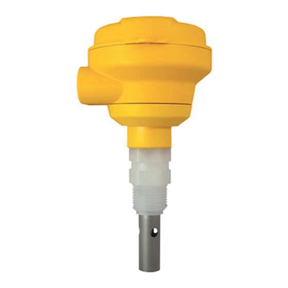
Signet 2850 Conductivity/Resistivity Sensor Electronics
*3-2850.090-1*
3-2850.090-1
Rev. K 03/15
3-2850-51, 3-2850-52
with ¾-in. adapter
3-2850-61, 3-2850-62, 3-2850-63
with Universal adapter
3-2850-51-XX, 3-2850-52-XX
Integral System
•
English
•
Deutsch
•
Français
•
Español
•
Italiano
Description
• Signet 2850 Conductivity/Resistivity Sensor Electronics provides either a two-wire
4 to 20 mA output or Digital (S
• The 4 to 20 mA output models provide eight ranges for each electrode cell constant,
plus the ability to invert each range.
• The EasyCal feature allows the devices to automatically recognize standard
conductivity test solution values for simple fi eld calibration.
• The Conductivity Sensor provided with integral systems will have its custom cell
constant information programmed into the electronics at the factory to provide a
2% sensor accuracy. See page 6 for details.
Table of Contents
Description ............................................................................................ 1
Dimensions ........................................................................................... 1
Warranty Information ............................................................................ 2
Product Registration ............................................................................. 2
Safety Information................................................................................. 2
Specifi cations........................................................................................ 2
Conductivity Sensor Dimensions .......................................................... 3
Operating Range Chart......................................................................... 3
In-Line Installation................................................................................. 4
Tank Installation .................................................................................... 4
4 to 20 mA Wiring ................................................................................. 5
Digital (S
L) Wiring ................................................................................ 5
3
Dual Input Wiring (Dual Digital (S
Cell Constant Selection ........................................................................ 6
Range Selection for 4 to 20 mA Output ................................................ 7
Calibration............................................................................................. 8
EasyCal ................................................................................................ 8
Dual Input Calibration ........................................................................... 8
Maintenance ......................................................................................... 9
Troubleshooting .................................................................................... 9
Electronic Certifi cation ........................................................................ 10
Ordering Information ........................................................................... 12
Dimensions
2850-51, -52 Integral mount
95 mm
3.74 in.
Operating Instructions
3
L) format.
L) Output) ........................................ 5
3
2850-61, -62, -63 Universal mount
85 mm
3.34 in.
English
95 mm
3.74 in.
82 mm
3.24 in.
Advertisement
Table of Contents

Related Manuals for GF Signet 2850


Summary of Contents for GF Signet 2850
-
Page 1: Table Of Contents
3-2850-51, 3-2850-52 Description with ¾-in. adapter • Signet 2850 Conductivity/Resistivity Sensor Electronics provides either a two-wire 4 to 20 mA output or Digital (S L) format. • The 4 to 20 mA output models provide eight ranges for each electrode cell constant, plus the ability to invert each range. -
Page 2: Warranty Information
Service Form and goods must be Temperature Compensation ..PT-1000 RTD (2% per °C) returned to your local GF Sales offi ce or distributor. Pure Water Compensation ..Auto-switching when using Product returned without a Service Form may not be 0.01 cell and raw conductivity... -
Page 3: Conductivity Sensor Dimensions
Conductivity Sensor Dimensions 73.7 mm 59.3 mm 2.90 in. 2.33 in. 35.8 mm 41.9 mm 21.5 mm 26.8 mm 1.41 in. 1.65 in. 1.13 in. 0.85 in. 3-2839 3-2840 3-2841, 3-2842 4.6 m (15 ft) T1 = 50 mm (2.0 in.) cable (std) T2 = 64 mm (2.5 in.) 152 mm... -
Page 4: In-Line Installation
In-Line Installation Tank Installation While the 2850-5X and 2850-6X electronics cannot be submerged, either model will accommodate tank installation. Select any electrode with a 5 m (15 ft) cable. The cable may be cut to length, but it CANNOT BE EXTENDED. The universal adapter included with 2850-6X models can Most of the Conductivity/Resistivity electrodes be attached to the top of a tank or mounted to a surface near... -
Page 5: To 20 Ma Wiring
4 to 20 mA Wiring Maximum length of 4 to 20 mA loop is 300 meters (1000 ft) Sensr Gnd 4-20 mA Loop Output (SHIELD) Temp. IN (WHITE) Signal RTN (BLK) Signal IN (RED) Digital (S L) Wiring 3-8900.621C I/O Module 3-8900.401-X +5VDC (Black) The Digital (S L) output is compatible with the... -
Page 6: Cell Constant Selection
NOTE: Cell Constant Selection To work correctly with the 9900, the 2850 must be set for the Single Input 2850 Electronics custom cell constant or the actual (2850-51, 2850-52, 2850-61, 2850-62) electrode cell constant and the • Single input models use only SW3. 9900 set for a 1.0 cell constant. -
Page 7: Range Selection For 4 To 20 Ma Output
Range Selection for 4 to 20 mA Output • The Range selection switch bank (SW2) provides eight range selections for each cell constant. • Each range can be inverted, making a total of 16 range options. • Select a range from the table below and set SW2 as indicated. Example (refer to shaded selections of chart): •... -
Page 8: Calibration
2850 electronics as its default factory value. If required, the sensor can be recertifi ed by contacting the GF Signet repair department. SW2: 4 to 20 mA output range selection switch bank Power and Output terminal block: 4 to 20 mA or... -
Page 9: Maintenance
Maintenance The 2850 requires no periodic maintenance. • Coatings on the electrode may cause slow response or drift. • Clean metallic surfaces with a mild detergent and a non-abrasive brush or cotton swab. Troubleshooting LED and Output Condition Possible Causes Suggested Solutions •... -
Page 10: Electronic Certifi Cation
Electronic Certifi cation Signet offers conductivity simulators in fi ve different values. These tools enable the user to validate the performance of the electronics independently of the electrode. This requirement is defi ned by ASTM D 1125-95 (Standard Test Methods for Electrical Conductivity and Resistivity of Water) which is commonly used for USP 24 applications. - Page 11 Notes 2850 Conductivity/Resistivity Sensor Electronics...
-
Page 12: Ordering Information
Ordering Information Signet 2850 Conductivity/Resistivity Sensor Electronics *All versions include EasyCal Mfr. Part No. Code Description 3-2850-51 159 001 398 2850 Sensor Electronics with Digital (S L) Output and ¾ inch adapter 3-2850-52 159 001 399 2850 Sensor Electronics with 4 to 20 mA Output and ¾ inch adapter...
Need help?
Do you have a question about the Signet 2850 and is the answer not in the manual?
Questions and answers