Table of Contents
Advertisement
Quick Links
Advertisement
Table of Contents

Related Manuals for Omron FZ4 Series


Summary of Contents for Omron FZ4 Series
- Page 1 Vision Sensor FZ4 Series User’s Manual Cat. No. Z318-E1-02B...
- Page 2 When using the FZ4 Series, be sure to observe the following: • The FZ4 Series must be operated by personnel knowledgeable in electrical engineering. • To ensure correct use, please read this manual thoroughly to deepen your understanding of the product.
-
Page 3: Table Of Contents
Layout of Main Screen (RUN Window)…………………………………………………………………14 Layout of Edit Flow Window ……………………………………………………………………………17 Layout of Property Setting Window ……………………………………………………………………19 Checking System Configuration …………………………………………………………………………21 Basic Configuration of FZ4 Series………………………………………………………………………21 Description of Model-specific Functions ………………………………………………………………22 Preparing Controllers and Cameras ………………………………………………………………………23 Preparing Controllers ……………………………………………………………………………………23 Adjusting Cameras ………………………………………………………………………………………23... - Page 4 Renaming a Scene and Adding a Description…………………………………………………………68 Editing Scene Groups ………………………………………………………………………………………70 Copying a Scene Group …………………………………………………………………………………70 Deleting a Scene Group …………………………………………………………………………………71 Renaming a Scene Group ………………………………………………………………………………71 ………………………………………73 3. Performing Test Measurement/Starting Operation ADJUST Window and RUN Window………………………………………………………………………74 ADJUST Window …………………………………………………………………………………………74 RUN Window ……………………………………………………………………………………………74 Switching to the RUN Window …………………………………………………………………………76 Switching to the ADJUST Window ……………………………………………………………………76...
- Page 5 Registering Image ………………………………………………………………………………………132 Loading an Image ………………………………………………………………………………………135 Using Account Functions …………………………………………………………………………………136 Setting Accounts (Account List) ………………………………………………………………………136 Sets the layout restrictions ……………………………………………………………………………140 Setting User Group Operation Restrictions …………………………………………………………141 Saving/Loading/Deleting the Contents of Security Settings ………………………………………146 Switching the User Account ………………………………………………………………………………150 Logging in ………………………………………………………………………………………………150 Logging out………………………………………………………………………………………………151 Using Custom Command …………………………………………………………………………………152 Startup the I/O command customize tool ……………………………………………………………152...
- Page 6 Setting the Encoder Trigger [Encoder Trigger Setting] ……………………………………………353 Setting the STEP Input Detection Pulse Width [STEP Setting] ……………………………………355 Setting a Network Drive [Network Drive Setting] ……………………………………………………356 Checking System Information [System Information] ………………………………………………358 7. Methods for Connecting and Communicating with External Devices …………359 About Connecting with External Devices ………………………………………………………………360 Communicating through Serial Communication (PLC Link) …………………………………………363...
- Page 7 About Serial Interface (RS-232C/422 Connection) …………………………………………………578 Measurement Mechanism ………………………………………………………………………………580 Color Processing Mechanism …………………………………………………………………………580 Search Processing Mechanism ………………………………………………………………………580 Edge Detection Measurement …………………………………………………………………………584 Defect Detection Measurement ………………………………………………………………………587 Handling Coordinates …………………………………………………………………………………588 Terminology Explanations ………………………………………………………………………………590 Basic Knowledge about Operations ……………………………………………………………………594 Inputting Values …………………………………………………………………………………………594 Inputting Text ……………………………………………………………………………………………594 Selecting Files and Folders ……………………………………………………………………………595 Available Operations in Select File Window …………………………………………………………597 Using the Zoom Function ………………………………………………………………………………598...
-
Page 8: Conventions Used In This Manual
The symbols used in this manual have the following meanings. Indicates relevant operational precautions that must be followed. Indicates operation-related suggestions from OMRON. Use of Quotation Marks and Brackets In this manual, menus and other items are indicated as follows. - Page 9 Communication The communication command is now Reference: "User's Manual", "Methods for Connecting command added. and Communicating with External Devices" (p.359) addition Supported software version: 4.20 or later EtherNet/IP The EtherNet/IP message communication Reference: "User's Manual", "Communicating with message function is now supported. the controller with Ethernet/IP message communication Supported software version: 4.20 or later...
- Page 10 : If the level of disturbance of the video is such that characters on the monitor are readable, the test is a pass. • This product complies with EC Directives.EMC-related performance of the OMRON devices that comply with EC Directives will vary depending on the configuration, wiring, and other conditions of the equipment or control panel on which the OMRON devices are installed.
-
Page 11: Before Operation
Before Operation This chapter describes the basic flow and preparations before beginning operation. Reference: Operation Flow (p.10) Reference: Layouts of Screens/Windows (p.11) Reference: Checking System Configuration (p.21) Reference: Preparing Controllers and Cameras (p.23) Reference: Input Operations (p.25) Reference: Returning Controller to Factory Settings (p.27) Reference: Saving Settings and Turning Power Off (p.28) Reference: Setting Operation Mode (p.30) FZ4 User's Manual... -
Page 12: Operation Flow
Operation Flow Here describes the operation flow. Operation Flow FZ4 User's Manual... -
Page 13: Layouts Of Screens/Windows
Layouts of Screens/Windows Screens vary with the status of the operation being performed. The structure of some typical screens and the functions for the various buttons are described here. Layout of Main Screen (ADJUST Window) This screen is used to check whether measurement is being performed correctly according to the set conditions. - Page 14 Menu Bar Select operations and settings menus related to measurement. Measurement Information Display Area Overall judgement Displays a scene's overall judgement result ( [OK]/ [NG]). Processing time Displays the time required for the measurement process. Status display Displays the scene group number, scene number, external output status, and image mode for the currently displayed scene.
- Page 15 Starts/stops measurement. Switch to RUN mode ● Switches to the RUN window. Image Display Area Displays the measured image. Property setting buttons Displays the name of the currently selected processing item.Moving to the property setting window can be done by tapping here. Control Area Displays "Test measurement", "Flow", "Detail result", and "Image display".
-
Page 16: Layout Of Main Screen (Run Window)
Image display ● Sets the display method for the Image Display area. Measurement Manager Bar [Capture] Saves the content displayed on the monitor as an image. Reference: Set the save destination for captured images. (p.104) [LCD Off] (Displayed only with LCD-integrated controllers.) Turns off power to the LCD monitor. - Page 17 Measurement Information Display Area Overall judgement Displays a scene's overall judgement result ( [OK]/ [NG]). The judgement results for each processing unit are displayed in the Control area. Processing time Displays the time required for the measurement process. Scene Group Name, Scene Name Displays the scene group number and the scene number of the currently displayed scene.
- Page 18 Control Area Displays [Flow], [Detail result], [Image display], and [Tool box]. Flow ● Displays the judgement results for the flow and each unit. 1. Moves to the top processing unit with an NG error. 2. Moves to the next processing unit with an NG error. Note The size of the processing unit buttons can be changed through [View] menu - [Display the enlarged flow] in the ●...
-
Page 19: Layout Of Edit Flow Window
Measurement Manager Bar [Capture] Saves the content displayed on the monitor as an image. Reference: Set the save destination for captured images. (p.104) [LCD Off] (Displayed only with LCD-integrated controllers.) Turns off power to the LCD monitor. Tap the bottom of the monitor screen to turn on power to the LCD monitor again. - Page 20 Searching can be performed to find out what position a processing item occupies in the unit list. The icon for the processing item to be searched for is selected in the processing item tree and clicked. This function is convenient when setting long flows. Select top/Select bottom ●...
-
Page 21: Layout Of Property Setting Window
Show guide ● When checked, explanations for processing items are displayed. Enlarge flow ● When checked, the "a Unit list" flow is displayed with large icons. Enlarge item tree ● When checked, the "f Processing item tree" is displayed with large icons. Ref. - Page 22 with the item on the left. Detail Area Set detailed items. Image Display Area Displays camera images, figures, and coordinates. Zoom Browser Area Zooms in and out from the displayed image. Layouts of Screens/Windows FZ4 User's Manual...
-
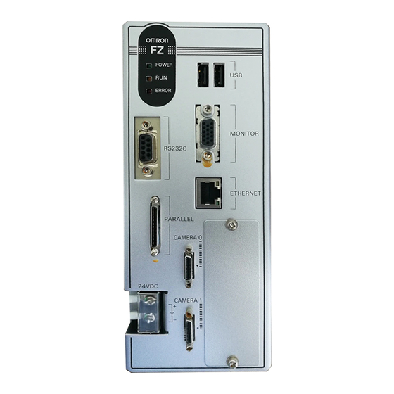
Page 23: Checking System Configuration
This product is a vision sensor for performing image processing measurement through a controller of objects photographed using a camera. By connecting an external device such as a PC, measurement commands can be input and measurement results can be output from the external device. Basic Configuration of FZ4 Series Controller integrated with LCD Box-type Controller... -
Page 24: Description Of Model-Specific Functions
Description of Model-specific Functions Operation mode With the multi core CPU installed, different operation modes can be set to meet different purposes of use. A desired operation mode can be selected from [Parallel-operation high-speed mode], [Single-line high-speed mode], [High-speed logging mode], [Non-stop adjustment mode] and [Multi-line random-trigger mode]. -
Page 25: Preparing Controllers And Cameras
Preparing Controllers and Cameras Preparing Controllers No special preparation is required with this product as processing items are pre-installed.Please check that the controller is switched on and that the Main screen is displayed. For details, see the User's Manual. The first time the program is started up, the Language Setting window is displayed, so select the language. -
Page 26: Intelligent Camera (With Lighting Function)
Important When using a small-size digital camera, check that the model and serial number of the camera head ● and camera amplifier match.When a camera head and camera amplifier of different models and serial numbers are connected, they may not operate correctly. Intelligent Camera (with Lighting Function) Proper lighting is of crucial importance to vision sensors. -
Page 27: Input Operations
Input Operations Input operations differ depending on the type of controller. Controller integrated with LCD: Operation with touch pen ● BOX-type controller: Operation with mouse and trackball ● Operation of Touch Pen With a Controller integrated with LCD, perform the following operations when operating the touch screen with the touch pen. - Page 28 Click Press the left mouse button once. Perform when selecting items, etc. Note This document primarily describes operations using the term "tapping". When using a mouse or trackball, read ● "Tapping" to mean "Clicking". Drag Move the mouse with the left mouse button held down. Input Operations FZ4 User's Manual...
-
Page 29: Returning Controller To Factory Settings
Returning Controller to Factory Settings All controller settings can be restored to factory default status (initialization). In addition, the controller can be restarted. Reference: Initializing Controller [System Initialization] (p.27) ● Reference: Restarting Controller [System Restart] (p.27) ● Initializing Controller [System Initialization] Restores the controller to factory default status. -
Page 30: Saving Settings And Turning Power Off
Saving Settings and Turning Power Off Before turning off power to the controller, perform the following operations to save the data that you have set. The controller loads scene data from the flash memory each time during start-up. Therefore, if the power is turned off without saving data to the flash memory, any changes made will not be saved. - Page 31 Power to the LCD is turned off. Turning LCD On Again This function is specific to FZ4-600/700/1100 series LCD-integrated controllers. Tap the lower part of the monitor screen. Then, the LCD will be switched on. FZ4 User's Manual Saving Settings and Turning Power Off...
-
Page 32: Setting Operation Mode
Setting Operation Mode This section describes the operation mode (FZ4-11 /H11 only). Utilize the multi core CPU to set an operation mode appropriate for the condition of use. This function is effective in improving the takt time and reducing the downtime. For setting, use Startup setting. Reference: Setting the Start-up Status "Startup Setting"... - Page 33 Tap [ ] and select a desired operation mode. Tap [OK]. On the Main screen (ADJUST window), tap [Data save] in the toolbar to save the setting data. On the Main screen, tap [System] menu - [Controller] - [System restart]. The System Restart window is displayed.
-
Page 34: Operation Mode Selection Guidelines
Operation Mode Selection Guidelines This section describes how to set an operation mode suitable for your specific purpose. [Note 1]: Reference: About Multiple Image Input Function (p.559) High-speed Logging Mode Normally one CPU is used to perform measurement, image logging and image display. The FZ4-11 /H11 series performs processing using two CPUs, with one CPU used exclusively for measurement and the other performing non-measurement processing. - Page 35 Processing items supporting the aforementioned parallel processing are specified below. You can improve the takt time effectively by combining the applicable units using an ingenious processing flow. -: Not supported ○ : Supported Parallel Parallel Parallel Processing item Processing item Processing item processing processing...
- Page 36 ○ ○ Camera Switching Circle Angle Focus Measurement Image ○ Position Compensation Iris Switching ○ Search Trapezoidal Correction+ Conditional Branch ○ Flexible Search Filtering ○ Sensitive Search Background Suppression DI Branch ○ ECM Search Brightness Correct Filter Data Output ○ EC Circle Search Color Gray Filter Parallel Data Output...
-
Page 37: Single-Line High-Speed Mode
Single-line High-speed Mode Measurement is performed using 2 CPUs, which means that compared to conventional models twice the number of measurement targets can be inspected in the same time. In this Single-line High-speed Mode, CPU0 and CPU1 execute the same inspection flow alternately for each STEP input, to improve the multiple image input performance and reduce the takt time to as much as one half. - Page 38 1 CPU 2 CPUs (FZ4-11 /H11 only) Setting Operation Mode FZ4 User's Manual...
-
Page 39: Multi-Line Random-Trigger Mode
Multi-line Random-trigger Mode Use this mode if you want to measure 2 lines using 1 controller. Measurement can be performed independently on line 0 and line 1 in response to inputs from different cameras. Scene group data and scene data can be set separately for line 0 and line 1. You can switch the monitoring target between line 0 and line 1 using the Line button in the Image display setting area. -
Page 40: Non-Stop Adjustment Mode
Important If Ethernet is used, set a different port number for each line. ● RS-232C/422 can be set at line 0 only. ● If parallel communication is used, the I/O format changes. ● Reference: I/O Format (Parallel Interface) (p.543) Parallel communication can only be set at line 0. Line 1 uses the settings of line 0. ●... - Page 41 Tap the icon of the processing unit to be adjusted. To change the flow, do so by selecting [Edit flow] in the toolbar. The setting window for the selected unit appears. Change each processing unit. Tap [OK]. The setting window closes, and the screen returns to the Main screen. When changing judgement conditions for multiple processing units, repeat steps Reference: 3 (p.39) to Reference:...
- Page 42 The screen returns to the RUN window. Important When [Transfer data] is executed, the results of [Trend Monitor] and [Expression], etc. are cleared. ● If the scene or scene group was switched or any setting of a processing unit was changed during operation ●...
-
Page 43: Setting Scenes (Measurement Flow)
Setting Scenes (Measurement Flow) A measurement flow consisting of a series of combined processing items is called a scene.This chapter explains how to create and edit scenes. Reference: What Is a Scene? (p.42) Reference: What Is a Scene Group? (p.46) Reference: Creating a Scene (p.47) Reference: Processing Item Selection Guidelines (p.49) Reference: Editing Processing Units in Scenes (p.63) -
Page 44: What Is A Scene
What Is a Scene? Processing items for use with various measurement objects and measurement objectives are provided in this product. By combining and executing these processing items, measurement adapted to the purpose can be implemented. A combination of processing items is called a "scene" and scenes can be easily created by combining processing items that are suited to the measurement purpose from the list of processing items provided. - Page 45 Example) Normal measurement Note The processing item "Camera Image Input" is set in processing unit 0 beforehand. ● FZ4 User's Manual What Is a Scene?
- Page 46 Example) When adding Position Compensation for two measurement objects in the same field of view What Is a Scene? FZ4 User's Manual...
- Page 47 Example) When judging type from the image and dividing later inspection conditions according to type (branch processing) FZ4 User's Manual What Is a Scene?
-
Page 48: What Is A Scene Group
What Is a Scene Group? A "scene group" refers to a grouping of 32 individual scenes. Creating a scene group is convenient when increasing the number of scenes and when managing a number of scenes according to category. USB memory is required for creating a scene group. Scene group 0 is saved in the controller while scene groups 1 to 31 are saved in USB memory. -
Page 49: Creating A Scene
Creating a Scene This section explains methods for adding a new processing unit to a scene. Display the scene to edit on the Main screen. Reference: Switching Scenes and Scene Groups (p.65) Tap [Edit flow] in Toolbar. The Edit Flow window is displayed. Select a processing item to be added from the processing item tree. - Page 50 Continue to add processing units.Repeat the steps after Reference: 3 (p.47) . Note Limitations on settings ● The number of image input processing items that can be used is limited. Reference: About Limits on the Number of Image Input Processing Items Used (p.612) Either tap the icon of the processing unit to be set or tap the Set button.
-
Page 51: Processing Item Selection Guidelines
Processing Item Selection Guidelines Processing items for performing measurement are provided with this product. Application-oriented measurement can be configured by combining processing items or changing the settings of processing items. The method for searching for processing items appropriate to the target measurement is shown here. Reference: Selecting Measurement Processing Items Using a Chart (p.49) ●... - Page 52 Position Compensation Processing Item Selection Guidelines FZ4 User's Manual...
- Page 53 Locating (Measurement Objects Not Inclined) FZ4 User's Manual Processing Item Selection Guidelines...
- Page 54 Locating (Measurement Objects Inclined) Internal and External Inspection Processing Item Selection Guidelines FZ4 User's Manual...
- Page 55 Presence Inspection Dimension Inspection/Measurement FZ4 User's Manual Processing Item Selection Guidelines...
- Page 56 Burr Inspection Text Comparison/Inspection Processing Item Selection Guidelines FZ4 User's Manual...
- Page 57 Defect/Contamination Inspection Quantity Inspection/Measurement FZ4 User's Manual Processing Item Selection Guidelines...
-
Page 58: Selecting Measurement Processing Items According To The Measurement Method And Purpose
Inspection for Presence of Different Objects Hole Position Measurement Selecting Measurement Processing Items According to the Measurement Method and Purpose This section describes methods for selecting processing items appropriate to different measurement objectives such as counting quantities, checking for deformation, and checking for contamination. Reference: Measuring positions (p.57) ●... - Page 59 Reference: Measuring folding of papers and sheets (p.60) ● Reference: Checking the interior/exterior and direction (p.60) ● Reference: Checking for mixing of different objects (p.61) ● Reference: Checking for deformation (p.61) ● Reference: Inspecting characters (p.62) ● Reference: Reading barcodes (p.62) ●...
- Page 60 [Search] If the shape and background of the measurement object are constant, a processing item such as one that registers an image as a model and searches for this image is effective. Reference: "Processing Item List Manual", "Search" (p.57) Other positioning Detecting defects and foreign materials Method, objective...
- Page 61 Count Method, objective References [Edge Pitch] Effective when calculating the number of IC or connector pins. Reference: "Processing Item List Manual", "Edge Pitch" (p.162) Inspection for number of pins [EC Circle Search] Inspection of the Effective when inspecting by focusing on circular outline information. number of screws Reference: "Processing Item List Manual", "EC Circle Search"...
- Page 62 Measuring folding of papers and sheets Method, objective References [Defect] [Precise Defect (FZ4-Hxxx series)] Check for folding on plain Effective when checking for folding on plain works. measurement objects Reference: "Processing Item List Manual", "Defect" (p.290) Checking the interior/exterior and direction Method, objective References [Flexible Search]...
- Page 63 Checking for mixing of different objects Method, objective References [Flexible Search] Effective for inspection of mixing of different objects in which there are variations with markings and the shape of measurement objects. Reference: "Processing Item List Manual", "Flexible Search" (p.70) Inspection for mixing of different measurement objects with variations...
- Page 64 Inspecting characters Method, References objective [Date Verification] Inspection of the Effective when inspecting date character strings that show the production date, etc. The date verification date can be set automatically. Reference: "Processing Item List Manual", "Date Verification" (p.329) Inspection of [Character Inspection] arbitrary Effective when inspecting arbitrary character strings.
-
Page 65: Editing Processing Units In Scenes
Editing Processing Units in Scenes In the Edit Flow window, editing buttons in the window can be used to change the order of processing units within the scene or to delete processing units. Searching a processing unit ( ● Convenient when the processing unit you want to select is not displayed on the screen. Selecting a processing unit ( ●... - Page 66 Deleting a processing unit ( ● Deletes processing units within a scene. Changing the name of a processing unit ( ● Changes processing unit names within a scene. Unit names must begin with a character other than ° (semi-voiced sound symbol) and " (voiced sound symbol). Also, unit names cannot consist of only a single-byte number, only a "+", or only a ".".
-
Page 67: Switching Scenes And Scene Groups
Switching Scenes and Scene Groups Set-up can be changed by changing the scene. With factory settings, the default display is scene 0 when the power is switched on. In addition, multiple scenes can be created (Scene 1 to 31). Also, when combined with the scene group function, up to 1024 scenes can be set. Instructions for switching scene groups and scenes can also be performed from external devices. - Page 68 Tap [Switch] for the scene group. The Switch Scene Group window is displayed. Switch to the scene group to edit. Tap [ ] and select the scene group to edit. Select whether a scene group should be saved when switching to another scene group. Setting value Setting item...
-
Page 69: Editing Scenes
Editing Scenes Copying a Scene Copies and pastes scenes within a scene group. This is a convenient function for reusing a created scene with only one portion being changed. On the Main screen, tap [Scene] - [Scene maintenance]. The Scene Maintenance window is displayed. In the scene list, tap the source scene to copy, and then tap [Copy]. -
Page 70: Renaming A Scene And Adding A Description
Tap [Clear]. A confirmation message is displayed. Tap [Yes]. Scene data is cleared. Tap [Close]. Renaming a Scene and Adding a Description Arbitrary descriptions can be added to each scene.This is convenient for making settings more easily understandable when managing many scenes. On the Main screen, tap [Scene] - [Scene maintenance]. - Page 71 Set "Scene name", "Author" and "Note". Tap [...] for each item. The soft keyboard is displayed. Set the name and a description. "Scene name" and "Author" cannot be longer than 15 characters, and "Note" cannot be longer than 255 characters. °...
-
Page 72: Editing Scene Groups
Editing Scene Groups Copying or deleting can be done by scene group and scene groups can be arbitrarily renamed. Note Make sure to check that a USB memory device has been inserted before performing this operation. ● Copying a Scene Group On the Main screen, tap [Scene] - [Scene maintenance]. -
Page 73: Deleting A Scene Group
Deleting a Scene Group Delete scene group data. The data to be deleted is shown as follows. Names set for a scene group ● All scene data within a scene group ● On the Main screen, tap [Scene] - [Scene maintenance]. The Scene Maintenance window is displayed. - Page 74 Set "Scene group name". Tap [...] for the "Scene group name". The soft keyboard is displayed. Enter a new name. Use 15 characters or less to Input words. Tap [Close]. Editing Scene Groups FZ4 User's Manual...
-
Page 75: Performing Test Measurement/Starting Operation
Performing Test Measurement /Starting Operation This chapter describes tests methods for checking whether correct measurement can be performed at the set conditions and describes useful functions for operation. Reference: ADJUST Window and RUN Window (p.74) Reference: Performing Test Measurement (p.77) Reference: Key Points for Adjustment (p.79) Reference: Arranging the RUN Window (p.82) Reference: Useful Functions for Operation (p.88) -
Page 76: Adjust Window And Run Window
ADJUST Window and RUN Window After test measurement and remeasurement are performed, check the measurement results. If there are problems, adjust the processing item setting values of the processing units.If the measurement results are stable, switch to the RUN window and perform measurement. This section describes the ADJUST window and RUN window. - Page 77 Normal Mode RUN Window When processing is taking a long time, it is necessary to check processing items and setting values. The time required for measurement is also displayed with the measurement results, so use this for reference. Fast View Mode RUN Window Simplifies display items and makes the display speed faster.
-
Page 78: Switching To The Run Window
Switching to the RUN Window Tap [Switch to RUN mode] in the ADJUST window. Window switches to the RUN window. Note You can make settings so that the RUN window is displayed whenever power to the controller is turned on. ●... -
Page 79: Performing Test Measurement
Performing Test Measurement Test whether the intended measurement processing can be performed with the current setting contents.Look at test results and adjust the property settings of each processing unit. Perform measurement according to the conditions set in the displayed scene. Display the Main screen (ADJUST window). - Page 80 Note Test images can be saved.This function is called the logging function. After setting conditions, these test ● images can be used in performing test measurement again. Reference: Logging Measurement Values and Measurement Images (p.94) Important The measurement interval and display update interval will vary for continuous measurement with test ●...
-
Page 81: Key Points For Adjustment
Key Points for Adjustment This section describes key points for adjustment when aiming to improve measurement precision and shorten measurement time. Stabilizing Measurement This section describes key points for adjustment when measurement is not stable. There are two methods for improving measurement precision: Performing processing of images loaded from the camera (filtering) or adjusting settings and parameters. - Page 82 Erosion ● When there is bright noise in an image, bright areas are contracted to eliminate bright noise. When contrast of measurement images is low (defect inspection is unstable) The filtering items "Extract vertical edges", "Extract horizontal edges", and "Extract edges" are effective. Extract vertical edges ●...
-
Page 83: Shortening Processing Time
Shortening Processing Time Find out which processing units are taking the most time and adjust the parameters of these processing items taking time. Insert the processing item "Elapsed Time" after the processing unit for which time is to be measured. Execute measurement. -
Page 84: Arranging The Run Window
Arranging the RUN Window Displaying Multiple Windows Together Multiple images can be displayed side by side in the Image Display area. In "Image display" of the Main screen Control area, tap [ ] of the "Image layout" menu and select the number of images to be displayed. The camera image view in the Image Display area switches according to the selected contents. -
Page 85: Changing Display Contents
4 images are viewed together with one each at the left, right, upper, and lower positions. 4 images Suitable for when 4 cameras are connected and images are to be checked all at one time. Displays four small images at the bottom and also one larger selected image. This view is preferable when you wish to check details of a certain image when four cameras are connected. - Page 86 From the measurement flow, tap the processing unit to be displayed. Set each item in [Image display] of the Control area. Item Description This item changes the camera image mode. Image mode Reference: Image Mode List (p.84) Measurement results are displayed as a list in the Image Display area. Display contents are classified into "Input image"...
-
Page 87: Enlarging Measurement Images [Zoom Images]
The image that was scanned in the immediately preceding measurement is displayed. Images can Freeze be updated at any time during measurement. The latest NG error image resulting from an overall judgement is displayed. The latest measurement results are always shown in overall judgement and measurement time. In Last NG this case, the overall judgement result and measurement time may conflict with the camera images. -
Page 88: Switching The Run Window To Fast View Mode [Select Run Mode]
Tap [Flow] or [Detail result] in the Control area. Flow or details of measurement results are displayed. Tapping once again returns the screen to the previous status. When displaying both the flow and detailed results, you can change the size of the Display area of the flow and detailed results by dragging [Detail result]. -
Page 89: Changing Display Contents On The Run Windowmeasurement Information Display Area
Tap [ ] and select a mode. Set value Description [Factory default] [RUN - normal mode] Selects which mode is used to display the RUN ● RUN - fast view mode window. ● Tap [OK]. The Select RUN Mode window closes. Changing Display Contents on the RUN Window Measurement Information Display Area The display contents on the RUN window measurement information display area can be changed. -
Page 90: Useful Functions For Operation
Useful Functions for Operation Remeasuring Saved Images Images from when measurement, including test measurement, was performed can be saved.Remeasurement can be performed with saved images after conditions are adjusted in order to check whether the adjustment is appropriate. The logging function is used for saving images. Reference: Setting Logging Conditions [Logging Setting] (p.96) Images that can be remeasured include images saved in the controller and images saved in USB... -
Page 91: Improving Adjustment Efficiency
Check "Measure using selected img (Re-meas.)". Tap [Measure] in the toolbar on the Main screen. Measurement of the selected image is performed. Note About Auto Re-meas. ● Displayed images can be automatically remeasured by placing a check in "Auto Re-meas.". Important When remeasuring an image with the controller, it is necessary to have a camera connected that is ●... - Page 92 If OK is selected If NG is selected Select the processing for the measured image. For "Adjust setting" Tap the [Adjust setting] button. For "Move Image file" Specify the save destination and tap [OK]. Tap the [Move Image file] button. Tap the [Skip] button to skip processing and remeasure the next image.
-
Page 93: Changing Judgement Conditions Without Stopping Measurement
Changing Judgement Conditions without Stopping Measurement Using the simplified non-stop adjustment function makes it possible to change the judgement conditions of processing units of the currently displayed scene without stopping the measurement processing being executed. Note The simplified non-stop adjustment function can only be used in RUN window normal mode. However, it cannot ●... -
Page 94: Changing Regions As A Batch [Shift Area]
Change the judgement conditions of each processing unit. Tap [OK]. The Judgement window closes, and the screen returns to the Main screen. The changed contents are shown in the displayed scene. When changing judgement conditions for multiple processing units, repeat steps Reference: 3 (p.91) to Reference: 5 (p.92) . -
Page 95: Monitoring Measurement Value Trends
Select the processing item in which to change the region. Only image setting processing items included in "Input image" and "Compensate image" are displayed. Select the registration region to change. Tap [Move] and input the value or tap the arrows to move the image. Images can also be directly dragged and moved. -
Page 96: Logging Measurement Values And Measurement Images
Reference: "Processing Item List Manual", "Trend Monitor" (p.506) Note If the measurement value is within the alarm range, the "Warning" message is shown on the screen. ● If a result output-related processing item is used, this allows for output to external devices when a warning ●... - Page 97 following kinds of adjustment. Logging Current Image [Save Last Logging Image] This section explains the method for logging the latest input image being displayed. On the Main screen, tap [Measure] menu - [Save last logging image]. The Logging Setting window is displayed. FZ4 User's Manual Useful Functions for Operation...
- Page 98 Set the logging images save destination. Specify the image file save destination (RAMDisk or USB memory). Edit the file name as required. Tap [OK]. After the logging operation is complete, the Save Last Logging Image window closes. Setting Logging Conditions [Logging Setting] Set the logging timing and the save destination.
- Page 99 Setting value Setting item Description [Factory default] No images are saved. [None] When logging images with the processing item "Image Logging", select [None]. Image Only NG Only images with an overall judgement of NG are saved. Logging All measured images are saved. Note, however, that some images may not be saved if "Measurement"...
- Page 100 Switch Checked If checked, OK/NG folders are automatically created and image ● saving folder [Unchecked] files are divided by scene and saved. ● by judge "Save to memory + file" setting example and save destination Example of setting Destination Folder name: USBDisk Saving will be performed as follows for the settings ●...
- Page 101 Setting value Setting item Description [Factory default] [None] Measurement data is not saved. Measurement data is saved when an NG error occurs in a unit before Data Only NG "Data Logging". If an NG error occurs after the "Data Logging" Logging processing unit, data logging is not performed.
-
Page 102: Analyzing Logging Data
Important Logging images saved in the controller memory are overwritten starting with the oldest image if the upper limit ● for the number of save images is exceeded. Reference: About Number of Logging Images (p.611) The data saved in the controller memory or RAMDisk is deleted when the controller is restarted. ●... - Page 103 Use Excel graphing and functions to process and analyze data. For example, the optimum threshold value can be calculated. Comparing Logging Data and Logging Images Compare image and measurement data to confirm correctness and to make analyzing trends for when NG occurs easier.
-
Page 104: Clearing Measurement Results
measurement IDs based on the measurement date and time. One image data file contains the camera image data of all the connected units. In this way, measurement data can be made to always correspond with image data. Verify data with the measurement ID. Clearing Measurement Results Clears all of the currently displayed scenes. -
Page 105: Capturing Screens
Tap [OK]. Note If you want to keep the logged images as files, save the logged images to the USB memory device by tapping ● [Data] - [Save to file] - [Logging image] before clearing them. Reference: Saving Logging Images to RAMDisk/USB Device (p.336) Capturing Screens The contents displayed in the monitor screen can be captured.Saved images can be loaded into the PC and pasted to documents. -
Page 106: Using The Operation Log Functions
Note The following windows cannot be captured. ● The window to select a file or a folder ● Confirmation message window when LCD is turned off ● Setting the Save Destination for Captured Images Sets the save destination for the image captured with the screen capture function. On the Main screen, tap the [System] menu - [Screen capture] - [Screen capture setting]. - Page 107 This item sets the operation log parameters. Setting item Description Start logging Place a check here to record the operation log from start-up The setting will be on boot reflected from the next time that the system starts up. Specify the name of the folder to save the operation log to. The operation log file name is the date and time at which the operation log was started + the "log"...
- Page 108 Checking and changing the operation log status Check the current operation log function status as follows. On the Main screen, tap the [Measure] menu -> [Operation log] -> [Operation log state]. The current operation log status is displayed. To change the current operation log status, tap either [Start] or [Stop]. To close the window, tap [Cancel].
- Page 109 On the Main screen, tap [Data] - [Save to file]. The "Save to File" window is displayed. Tap the Copy files tab. FZ4 User's Manual Useful Functions for Operation...
- Page 110 Select [Select folder], then tap [...], and specify the folder. Select the operation log (*.log). Useful Functions for Operation FZ4 User's Manual...
- Page 111 Specify the destination. Tap [OK]. For details on operation logs, see "Operation log format" in the Appendix. Reference: Operation log format (p.625) FZ4 User's Manual Useful Functions for Operation...
- Page 112 Useful Functions for Operation FZ4 User's Manual...
-
Page 113: Using Tool
Using Tool This section describes adjustments during startup and convenient tools for operations. Reference: Using NG Analyser (p.112) Reference: Using User Data Tool (p.119) Reference: Outputting a List of Scene Data Setting Values (p.122) Reference: Saving Image Files to RAMDisk/USB Device (p.129) Reference: Using Registered Image Administration Tool (p.132) Reference: Using Account Functions (p.136) Reference: Switching the User Account (p.150) -
Page 114: Using Ng Analyser
Using NG Analyser Start the NG analyser by selecting [Tool] - [NG analyser] from the controller menu. This tool, which analyzes setting flows, is used mainly in 2 ways. Adjustment of measurement setting values during start-up ● Use sample work images to analyze optimal setting values for the processing flow. Analysis of NG causes during operation ●... -
Page 115: Layouts Of Ng Analyser Screens
Layouts of NG Analyser Screens Analysis result display area List of units A list of units currently set is shown together with analysis results. Details of unit Detailed analysis results of each unit are shown. Details of data Detailed results of analysis data are shown. Sets magnification to display. - Page 116 Image display area Displays selected images. Image selection Selects the image number to be displayed in the image display area. Images can be displayed by directly tapping the analysis result window. Control area Target Sets images to be measured. Standard image Sets the image to be used as a reference for analysis.
-
Page 117: Using Method Of Ng Analyser
Measurement data Display the desired unit in the list of units and select the unit based on details of unit and details of data. Using Method of NG Analyser Important Classify sample images beforehand into the OK folder containing images you want to judge OK or NG folder ●... - Page 118 The files in the folder are displayed. Tap [Execute batch measurement]. All images in the folder are measured in batch. Measurement results are displayed. The results in the OK folder are shown first, followed by the results in the NG folder. Green indicates OK, while red indicates NG.
- Page 119 In the above example, [Search] becomes the adjustment target. The cause of NG is displayed. To check the details of values further, tap [Details of data]. Adjust the processing item by referring to the displayed content. In the following example, Correlation values are clearly lower on some screens. Based on the revealed cause of false judgement, use the [Set up(Std.)] and [Set up(Select)] buttons to change the setting values of the processing unit.
- Page 120 Repeat steps 5 to 8 to correct the setting values corresponding to all causes of false judgement. Select [Execute batch measurement] to confirm that no images are falsely judged. If there are still falsely judged images, repeat the same procedure until a re-measurement finds no falsely judged images.
-
Page 121: Using User Data Tool
Using User Data Tool This tool is used to share data within the controller. The data set in the user data is shared between scenes and scene groups, respectively. In the multi-line random trigger operation mode, however, data cannot be shared beyond the lines. The data variables created are stored to the user data region on the controller. - Page 122 Tap the data that is to be set. Specify the initial value for the data. Setting value Item Description [Factory default] -999999999.9999 to 999999999.9999 Set the specified user data Data [0.000] value. Enter the comment for the data. The entered comment will be displayed in the comment field of the user data processing item. Using User Data Tool FZ4 User's Manual...
- Page 123 Setting value Item Description [Factory default] Up to 64 characters Set the comment for the specified user Comment [Space] data. Repeat steps 2 to 4, and set the user data. To stop the user data tool, tap [OK]. Tap [Data save] to save the specified user data to the controller. FZ4 User's Manual Using User Data Tool...
-
Page 124: Outputting A List Of Scene Data Setting Values
Outputting a List of Scene Data Setting Values Use the setting values download/upload function to create a list of scene data setting values. With the setting values download function, the specified scene data setting values can be output to a CSV file. - Page 125 Select the scene with the setting values to be downloaded. Tap [...]. FZ4 User's Manual Outputting a List of Scene Data Setting Values...
-
Page 126: About Downloaded Csv Files
Specify the save destination folder and file name, and tap [OK]. Tap [OK]. The data will be saved to the save location. About Downloaded CSV Files The character code of the downloaded CSV file is Unicode (UTF-8). The file can be opened with Windows notepad. When using another editor to open the file, set the character code to Unicode (UTF-8). - Page 127 SceneTitle,Scene title name,Author,Note #Processing item number in the flow,Processing item identifier,Processing unit title name Identifier,Data title name,Data Double byte characters are enclosed in the double quotation marks ("). Refer to each processing item in the Processing Item List Manual and the external reference tables for each data parameter.
-
Page 128: Uploading Setting Values
Uploading Setting Values Upload the CSV file downloaded under "Downloading Setting Values". Switch to the scene group that contains the scene with the setting values to be uploaded. When reading from USB memory, plug a USB memory device into the controller. On the Menu window, tap [Tool] and then [Settings download and upload tools]. - Page 129 Tap [...]. Important To upload the file, set the character code to Unicode (UTF-8) with Windows notepad etc., then save the ● file in CSV format. Specify the folder and the name of the file to be loaded, and tap [OK]. FZ4 User's Manual Outputting a List of Scene Data Setting Values...
- Page 130 Tap [OK]. The data will be uploaded. Important If data with fewer units than the scene data to be loaded is uploaded, the parts that do not exist in the CSV file ● will not change. (Example) In such a case, the processing item for Unit 3 will be changed from Camera image input to Defects/ Contamination.
-
Page 131: Saving Image Files To Ramdisk/Usb Device
Saving Image Files to RAMDisk/USB Device This saves logging images and image files saved in the controller to the RAMDisk or USB memory. The storage format (Bitmap or Jpeg) can be specified when they are saved. Important During saving, do not restart, turn off power or remove the USB memory. The data can be corrupted. ●... - Page 132 Tap [OK]. The logging image is saved to the selected destination. If a file with the same name already exists in the destination folder, the newly saved file is written over that old one. Saving image files When saving to USB memory, plug a USB memory device into the controller. On the Main screen, tap [Tool] - [Image file save].
- Page 133 Specify the save destination folder name and the format. Setting value Setting item Description [Factory default] Folder name - Specify the save destination folder name. [Bitmap] ● Format Select the image format to be saved. Jpeg ● 0 to 100 Quarity Set the quality when the image is to be saved in Jpeg format.
-
Page 134: Using Registered Image Administration Tool
Using Registered Image Administration Tool You can save images used for model registration and reference registration as registration images and can reference them later and use them for re-registration and adjustment of reference positions etc.. You can register the "Latest logging Image", "Logging Image", and "Image File". Important USB memory is required for using this function. - Page 135 Select the image to register. Setting item Setting value Description Last logging This registers the image logged last and being used for image measurements. Registered Image This registers the logging image saved in the main memory. Tap Image registration ] to select an image to save. Image File This registers an existing image file.
- Page 136 Select the index number of the image to delete. Note When more than one image is included in the registration images, tap the [<<] or [>>] symbol under the ● preview window as necessary to move forward or back to the desired image. Tap [Delete].
-
Page 137: Loading An Image
Loading an Image A registered image can be loaded as a measurement image. On the Main screen, tap [Tool] menu -> [Registered Image Administration Tool]. The [Registered Image Administration Tool] screen is displayed. Select an index number of the reference image to load. Note: When more than one image is included in the registration images, tap the [<<] or [>>] symbol under the ●... -
Page 138: Using Account Functions
Using Account Functions You can restrict access to the controller by specific users and affiliated user groups. Because you can set a password for each user and can enable/disable operations for each user group, you can flexibly manage users to match the way they use the system, for example system administrators, managers at the actual operation sites, operators actually using the system, etc. - Page 139 Set the user information. Setting item Description Enter a user name of 2 to 20 single-byte alphanumerics. Uppercase and lowercase User name characters are recognized as different characters. Select the user group (UG0-UG7) to which the user being added will belong. Group If you select "UG0", the user can use all functions.
- Page 140 Tap the user to change the affiliated group or password for. Tap [Change group] or [Change password]. Change the affiliated group or password. Tap [OK]. The user information is changed. Deleting an account Delete a user account as follows. On the Main screen, tap the [Tool] menu - [Security Settings]. The security settings window is displayed.
- Page 141 Tap the user to be deleted. Tap [Delete user]. A confirmation message is displayed. Tap [Yes]. The user account is deleted. Setting automatic logout Set the length of time before an account is automatically logged out when no operation is performed as follows.
-
Page 142: Sets The Layout Restrictions
Tap [Close]. Sets the layout restrictions Set the rights to change the layout for each user group. You can restrict the functions that can be operated by each user group. The layouts that can be restricted are as follows. ADJUST Window Security setting items Other Menu bar... -
Page 143: Setting User Group Operation Restrictions
In the Item tab area, tap [Layout restrictions]. Change the layout restriction settings. Tap [Close]. Setting User Group Operation Restrictions You can restrict the functions that can be operated by each user group. The operations that can be restricted are as follows. ADJUST Window Security setting Other... - Page 144 Image Image display display Positions Display > Positions setting setting panel > panel > Positions Positions Display > Image layout > 1 screen Image Image display display Display > Image layout > 2 screens setting setting Image layout Display > Image layout > 4 screens panel >...
- Page 145 Tool box > Logging image Clear Measurement > Clear logging image clear logging image Tool box > Save last logging Save last Measurement >Save last logging image image logging image Data save Tool box > Data save Data > Data save button Data save Save to file...
- Page 146 STEP signal filter System > Controller > STEP setting setting Encoder trigger System > Controller > Encoder trigger setting setting Network drive System > Controller > Network drive setting setting System System > Controller > System initialization initialization Tool box > System restart System >...
- Page 147 In the item tab area, tap [Operating restrictions]. Check the operations to be restricted. Operations that are not checked are not restricted. Check the operations to be permitted in units of right side user groups (UG1 - UG7). FZ4 User's Manual Using Account Functions...
-
Page 148: Saving/Loading/Deleting The Contents Of Security Settings
Operations that are not checked cannot be operated by users belonging to that group. Tap [Close]. Operation restrictions are set for user groups. Saving/Loading/Deleting the Contents of Security Settings You can save user account and user group settings (security settings). You can load or delete saved settings. - Page 149 In the Item Tab area, tap [Setting Data]. Specify the save destination folder and file name. Tap [Save]. Loading the contents of security settings Load the saved user account and user group settings into the controller as follows. If the settings were stored to USB memory, insert the USB memory containing the security settings to load into the controller.
- Page 150 Select the file to load. Tap [Load]. Deleting security settings Delete saved user account and user group settings as follows. Important Note that the current security settings are all deleted. ● On the Main screen, tap the [Tool] menu - [Security Settings]. The security settings window is displayed.
- Page 151 In the Item Tab area, tap [Setting Data]. Tap [Execution]. The "After the migration is finished, saved console. OK?"confirmation message is displayed. Tap [Yes]. The old security settings are changed. Tap [OK]. Enter the user name and password to log in again. FZ4 User's Manual Using Account Functions...
-
Page 152: Switching The User Account
Switching the User Account Once a user account is set up, you can log in and log out with the registered user account. The login screen is also displayed even though you are already logged in, if you try to execute an operation you do not have the right to use. -
Page 153: Logging Out
Logging out Note If an automatic logout time is set, when you do not perform any operations at all for the set time period, you are ● automatically logged out. Tap [Login Icon] in the Measurement Information Display area. The login window is displayed. Tap [Logout]. -
Page 154: Using Custom Command
Using Custom Command Besides the commands that are available as standard, it is also possible to define and use individual commands. Startup the I/O command customize tool Important For remote operation, the I/O command customize is disabled. ● On the Main screen, tap [Tool]-[Customize I/O command]. Description of display elements are as below. - Page 155 Function Display and edit function name for selected comand. name Comment Display and edit comment for selected comand. Enable/ Set/display whether custom command is enabled. Disable If defined but not checked, it is not executed. Set/display whether to change to measurement stop state (MeasureStop) before executing command.
- Page 156 Selecting a macro command in the Command Reference Window displays the Command Input Window and the Command Reference. Define the command. Using macro program rules, the command reference, the system data list, and the IO module list as reference, define the command. Description of display elements are as below.
-
Page 157: Common Behavior Of Customize Io Command
Space Insert blank character on current position of Macro edit window. Delete previous character of the current position of Macro edit window. Delete next character of the current position of Macro edit window. Enter Insert new line on current position of Macro edit window. Tap [OK]. - Page 158 Standard IO commands When the same command name / command id of standard IO commands are used for customize IO commands, customize IO command has the priority and the standard IO commands are not executed. If you execute the standard IO commands after execution of customize IO commands, please add the line as below.
- Page 159 Creating serial command Command parameters Received text string is split by space character(" ") into command and parameters, and stored in the predefined variables shown below: Variable name Type Content ArgmentsLength& Integer Number of parameters ArgmentString$() Array of text string Array of parameters (string) Array of parameters converted to number ArgmentValue#()
- Page 160 Variable name Type Content Command execution result CommandResponse& Integer 0 : Command processing successful Other than 0 : Command processing failed (The ERROR signal turns on.) Creating PLC Link Command Command parameters The command parameters are stored on the predefined variables as below. Variable name Type Content...
-
Page 161: Common Rules For Macro
Common rules for Macro Grammar of program approximately conform basic BASIC grammar, it also contains part contents that Macro program specially has. Please see each item for details. Reference: Calculation (p.159) Reference: Character (p.160) Reference: Comment (p.161) Reference: Constant (p.161) Reference: Convert Type (p.161) Reference:... - Page 162 Relational calculation is used in comparing between two values. If result is true, returns -1, otherwise returns 0. Logic calculation can be used to check more than one condition or operate with bit to designated value. Following is all kinds of logic calculation. Logic Calculation Content Example...
- Page 163 Comment We can add the comment arbitrarily in the Macro program if necessary. It is considered as comment from single quotation mark or rem command to the end of this line. Constant It can be classified to integer constant, double constant and character constant. The range of value is as follows: Integer Constant -2147483648 to 2147483647...
- Page 164 by arithmetic calculation and logic calculation. Composition of mathematic expressions is contained by brackets. Two mathematic expressions combine a relative expression by relative calculation sign. Character constant, character variable and function of return string compose the mathematic expression by plus sign. It can be the composition of many mathematic expression by brackets.
- Page 165 Reserved Word List Initial Reserved Word Character AddGlobalData AddSystemData ApproximationCircle BusyOut Case Catch chr$ ClearMeasureData close cont CopyMeasureImage CopyUnitImage crspoint date$ debug DisplaySubNo dposline DrawArc DrawArcW DrawBox DrawCircle DrawCircleW DrawCursor DrawEllipse DrawFigure DrawFillImage DrawJudgeText DrawLine DrawLineW DrawMeasureImage DrawPoint DrawPolygon DrawSearchFigure DrawText DrawTextG DrawUnitImage...
- Page 166 dskf ElapsedTime Else Elseif End Select End Try EndIf erase errcmnd$ errno ExecuteImageLogging exit do exit for fcopy GetAll GetGlobalData GetImageSize GetImageWindow GetPort GetSystemData GetUnitData GetUnitFigure gosub goto hex$ ImageFormat input # input$ isfile JudgeOut kill left$ line input # list load Loop While...
- Page 167 MeasureId$ MeasureProc mid$ mkdir Next open ParallelExecute piece$ print print # PutAll PutPort ReceiveData RenumUnitNo right$ rmdir RunOut Select SendData SendString SetDrawStyle SetGlobalData SetImageWindow SetMeasureImage SetSystemData SetTextStyle SetUnitData SetUnitFigure SetUnitJudge SetUnitTitle StartTimer Step stop str$ str2$ time$ FZ4 User's Manual Using Custom Command...
- Page 168 Timer TotalJudge TransformAngle TransformArea TransformDist TransformLine TransformXY UnitData UnitData$ UnitData2 UnitInfo UnitItemIdent$ UnitJudge UnitNo UnitTitle$ varpop varpush wait Wait Statement As command to deal with minimum unit, a statement can't have more than 245 characters. If a statement have more than 245 characters, there will be wrong. And program will suspend. Statement has following three types.
- Page 169 Variable Name The first character of variable is english character, not digital. Others of digital part are also be discerned. It can not use special symbol. To sum up as follow: First position:must be letter('A' to 'Z', 'a' to 'z') ●...
- Page 170 AA$="OMRON" B$$="OMRON"+"TATEISI" Array Variable We can use not more than 4 dimensions array variable. We can use dim command to define array variable. Additional numbers begin with 0. The number of element is "Additional number add 1". (Example) ...
-
Page 171: Debugging Macro Program
Debugging Macro program Overview Macro program may cause error while it is working, by illegal command call or incorrect value of parameters. Debugging support function will help you to find out the cause of the error and fix the problem. System behavior on error When error happened, system behaves as below : Show error on macro console... -
Page 172: List Of Macro Error Messages
List of macro error messages List of error No. If an error occurs during the execution of the command, the error number is displayed. Error No. Error message NEXT without FOR Syntax error RETURN without GOSUB Illegal function call Overflow Out of memory Undefined line number Subscript out of range... - Page 173 Do without Do statement occurs without a Check if there is a correct Loop statement corresponding LOOP corresponding Loop statement. Do statement. ELSE Else statement occurs without a Check if there is a correct Endif statement without corresponding Endif statement. corresponding Else statement.
-
Page 174: Macro Command Reference
Check the calling format and description of command or Wrong format or spelling of command or function using command reference. Check how to use Syntax error function. Or command or function is variables or arrays using Programming rules. used not following the rule. Reference: Common rules for Macro (p.159) Type of variables mismatch, such as... - Page 175 Arithmetic calculation Function Command name References Get the absolute value of the expression specified. Abs(Function) Reference: Detai l s (p.182) Get the logical product (AND) of 2 specified expressions. And (Function) Reference: Detai l s (p.184) Get approximate circle ApproximationCircle Reference: Detai l s (p.185) Get the arc tangent of the expression specified.
- Page 176 File control Function Command name References Closes the specified file Close Reference: Details (p.192) Get the available space of the drive. Dskf(Function) Reference: Details (p.202) Checks for the end of file. Eof(Function) Reference: Details (p.203) Copies a file within the memory card. Fcopy Reference: Details (p.208) Reads in the specified number of bytes of binary data.
- Page 177 Display control Function Command name References DisplayUnitNo Gets image/text Display the processing unit number Reference: Detai l s (p.200) (Function) Gets information about the Image Display window setting GetImageWindow Reference: Detai l s (p.212) Gets information about the text Display window setting GetTextWindow Reference: Detai l s (p.216) Update the indication of the image display window...
-
Page 178: Flow Control
Clear the scene number ClearScene Reference: Details (p.191) Copy the scene data CopyScene Reference: Details (p.193) Gets the available scene number SceneCount (Function) Reference: Details (p.261) Gets the explanation of the scene SceneDescription$ (Function) Reference: Details (p.262) Gets the scene creator name SceneMaker$ (Function) Reference: Details (p.264) Get the current scene number... - Page 179 Gets processing unit figure data GetUnitFigure Reference: Detai l s (p.217) Gets processing unit figure format ImageFormat (Function) Reference: Detai l s (p.222) Sets processing unit data SetUnitData Reference: Detai l s (p.276) Sets processing unit figure data SetUnitFigure Reference: Detai l s (p.276) Sets the processing unit title name SetUnitTitle Reference: Detai l s (p.278)
- Page 180 Get the arc tangent of the expression specified. Atn (Function) Arithmetic calculation Reference: Detai l s (p.187) Output BUSY state BusyOut IO module control Reference: Detai l s (p.188) Change scene group number ChangeSceneGroup Control scene group Reference: Detai l s (p.189) Change scene number ChangeScene Control scene...
- Page 181 Control processing Gets processing unit image size GetImageSize Reference: Detai l s (p.211) unit Set information about the Image Display window setting GetImageWindow Display control Reference: Detai l s (p.212) GetMeasureOut Gets measurement result the Output presence Measurement control Reference: Detai l s (p.213) (Function) Gets PLC the read data GetPlcData...
- Page 182 Load the Scene group data LoadSceneGroup Save/Load Reference: Detai l s (p.236) Load the scene data LoadScene Save/Load Reference: Detai l s (p.235) Load the System data LoadSystemData Save/Load Reference: Detai l s (p.236) Load the Processing unit data LoadUnitData Save/Load Reference: Detai l s (p.237) Loads the Program into the Controller memory.
- Page 183 Save the scene data SaveScene Save/Load Reference: Detai l s (p.259) Save the System data SaveSystemData Save/Load Reference: Detai l s (p.260) Save the Processing unit data SaveUnitData Save/Load Reference: Detai l s (p.261) SceneCount Gets the available scene number Control scene Reference: Detai l s (p.261) (Function)
- Page 184 Converts to a numeric character string with the numeric Str2$(Function) String operation Reference: Detai l s (p.281) value format specified. Reboot the controller SystemReset Others Reference: Detai l s (p.283) Gets the tangent of the specified expression. Tan (Function) Arithmetic calculation Reference: Detai l s (p.283) Reads out the time from the internal clock.
- Page 185 Description It is possible to specify an integer type or double-precision type as the storage destination for the return value. When an integet type has been specified, a rounded integer value is stored. Example Gets the difference between each coordinate of 2 points (X1,Y1)(X2,Y2). X1#=100 Y1#=200 X2#=200...
- Page 186 Adds system data AddSystemData <dataIdent0>, <dataIdent1>, <data> Parameters <dataIdent0> Set data ident 0 (character string type) Fixed to "PanDA" <dataIdent1> Set data ident name 1 (character string type) <data> Setting information (integer type/double-precision real type/character string type) Return Value None. Description Adds the system data of data ident1 and setting data in the data ident 0.
- Page 187 Example Get the logical product of 2 values X and Y. X&=15 Y&=8 DATA&=X& And Y& The result is as follows: DATA&=8 Get approximate circle ApproximationCircle <count>, <x()>, <y()>, <centerX>, <centerY>, <radius> Parameters <count> The number of coordinates that will be calculated for the approximate circle X coordinate array of the point for calculating the approximate circle (integer or <x()>...
- Page 188 Dim X&(3),Y&(3) X&(0)=50 Y&(0)=50 X&(1)=100 Y&(1)=100 X&(2)=150 Y&(2)=50 ApproximationCircle 3, x&(), y&(), centerX#, centerY#, radius# Get the value of the character code for the specified character. Asc (<Character String>) Parameters <Character String> The character string (character type) that requests the character code. Return Value Returns the value of the integer.
- Page 189 Return Value None. Description Register a processing item appointed with a <itemIdent> processing items with the position appointed with an <unitNo>. When a processing item has been already registered with the position of the <unitNo>, overwrite. Example Add a handling of search unit to the last of the flow. 'Acquire the number of the processing units.
- Page 190 Output BUSY state BusyOut <ioIdent>, <state> Parameters <ioIdent> Identification name(string) of I/O module that executes send processing State 0:OFF,1 <state> ON(integer type) Return Value None. Description Identification name(string) of I/O module that executes send processing is specified in argument<ioIdent>. The content of operation depends on the specification of the I/O module. Example Output BUSY ON to Parallel interface.
- Page 191 Change scene group number ChangeSceneGroup <sceneGroupNo> , <sceneNo> Parameters <sceneGroupNo> Scene group number to change(integer type) <sceneNo> Scene number to change(integer type) Return Value None. Description Change the scene group and the scene appointed with a <sceneGroupNo> and a <sceneNo>. Example Change to scene group 10.
- Page 192 Gets the character corresponding to the character code. Chr$ (<Expression>) Parameters <Expression> The expression (integer type) that requests the character code. Return Value Returns the character type string. The content of the value is ASCII code. Description Specify an integer from 0 to 255 in the <Expression>. When the value of the <Expression>...
- Page 193 Example Clear measurement data of processing unit 3. ClearMeasureData 3 Clear the scene number ClearScene <sceneNo> Parameters <sceneNo> scene number(integer type) Return Value None. Description The following processing is carried out in the scene clear for the scene. ・Clear the title of the scene. ・Delete all processing units in the scene.
- Page 194 Example Clear a scene group 1. ClearSceneGroup 1 Closes the specified file Close [#<File No.>[,#<File No.>]...] Parameters <File No.> The file number (integer) of the file to be closed. Return Value None. Description This closes a file that has been opened for data I/O processing. In <File No.>, specify the <File No.>...
- Page 195 Return Value None. Description This command is a direct command intented to start execution from the same location when the program is halted with the Stop command. While the program is stopped you can print the variable name, etc., however, if the content of the program is changed, there may be cases where it cannot be continued.
- Page 196 Copy the scene group data CopySceneGroup <srcSceneGroupNo> , <destSceneGroupNo> Parameters <srcSceneGroupNo> Scene group number of the origin of copy (integer type) <destSceneGroupNo> Scene group number of the copying (integer type) Return Value None. Description Copy the data of the scene group appointed with an <srcSceneGroupNo> to scene group appointed with a <destSceneGroupNo>.
- Page 197 Example Insert processing unit 3 of scene 2 before processing unit 4. CopyUnit 2 , 3 , 4 , 1 Copy the processing unit figure data CopyUnitFigure <srcSceneNo>, <srcUnitNo>, <srcFigureNo>, <destUnitNo>, <destFigureNo> Parameters <srcSceneNo> The scene number that is to be copied (integer type) <srcUnitNo>...
- Page 198 Description Copy the processing unit modle data. Example Copy the model 0 of processing unit 3 for scene 2 to model 0 of processing unit 5. CopyUnitModel 2, 3, 0, 5, 0 Gets the cosine of the specified expression. Cos (<expression>) Parameters <expression>...
- Page 199 <Straight Line 2nd The parameter of Straight Line 2 for getting the intersection (double-precision type Component> array) <X Coordinate> X coordinate storage region for the intersection that was gotten (double-precision). <Y Coordinate> Y coordinate storage region for the intersection that was gotten (double-precision). Return Value None.
- Page 200 Return Value Returns the value of the character type string. The content of the value is the character string in which the date from the internal clock is given as Year (YY), Month (MM) and Day (DD), separated by slashes (/). The range of the date returned is as follows.
- Page 201 Delete the processing unit DeleteUnit <unitNo> Parameters <unitNo> Processing unit number (integer type) Return Value None. Description Delete the processing unit registered with the position appointed with an <unitNo>. Example Delete the processing unit 2. DeleteUnit 2 Definition of the array variables is carried out. Dim <Array Variable Name>...
- Page 202 Description Specify the variable name to be used as the array in <Array Array Variable Name>. The array will be secured in the range from 0 to ... <Maximum Value of Subscript>.Thus, the number of array elements will be the <Maximum Value of Subscript> +1. Declare the array variable for the maximum 4th dimension.
- Page 203 The execution of the statements between Do and Loop are repeated as long as the conditions continue to be fulfilled. Do <Do statement within the block> Loop While <Logical Expression> Parameters <Logical Expression> The logical expression (Boolean expression) for controlling processing. <Do statement within the block>...
- Page 204 Return Value Returns the value of the double-precision type number. The content of the value is the shortest distance between the points and straight line. Description Specify the points to get the distance in <X Coordinate> and <Y Coordinate>. The parameters a, b and c that make up the straight line ax+by+c=0 are stored in <Straight Line Component>."a"...
- Page 205 Description When a drive that does not exist has been specified, -1 is returned as the return value. Specify the <Drive Name> in a manner similar to the following: "C:\". Example When the remaining available space on the drive is less than 1KB turn ON the ERROR signal. if Dskf("C:\")<1024 then putport "ParallelIo",103,1 Checks for the end of file.
- Page 206 Return Value None. Description Multiple arrays can be freed at one time. Use this command to free array variables that are used only temporarily. Doing so will allow the most effective use of memory space. An array that has been freed can be defined again under the same name. When an array is re-defined with the same name without freeing it, the array defined the most recently will be valid.
- Page 207 Writing data to a file. *DATAWRITE Try Open "/C0/DATA.DAT" for OUTPUT as #1 Print #1, DATA$ Close Catch ' In the case where the error is generated by the "open" command. If ERRCMND$ = "Open" Then ...
- Page 208 Type missmatch0 String too long Undefined array Line buffer overflow FOR without NEXT Undefined label CASE without SELECT END SELECT without SELECT SELECT without END SELECT CASE without END SELECT ELSEIF without IF ELSE without IF ENDIF without IF IF without ENDIF ELSEIF without ENDIF ELSE without ENDIF DO without LOOP...
- Page 209 Terminate the controller ExitFzProcess Parameters None. Return Value None. Description When is carried out on a controller, the power off of controller. Example Save the data to the controller, and then power off the controller. SaveData ExitFzProcess Calculate exponential function. Exp <Expression>...
- Page 210 Copies a file within the memory card. Fcopy <Original to be Copied>,<Copy Destination> Parameters <Original to be Copied> The path of the original that will be copied (character string type). <Copy Destination> The path for the copy destination file (character string type). Return Value None.
- Page 211 Description Truncates everything after the radix point for the specified value and return the value of the integer part. For example, Fix(-1.5) would return -1.Fix(1.5) returns 1. When an argument has been given a negative value, the int function returns an integer that does not exceed the maximum negative of the argument and in relation to this, Fix returns the minimum negative integer exceeding the argument.For example, if -7.2 is specified as the argument, the int function returns -8 and the Fix function returns -7.
- Page 212 Description The commands between For and Next are repeated and executed while changing from the initial value of the variable to the ending value. The commands between For and Next are repeated and executed while changing from the initial value of the variable to the ending value.
- Page 213 Example Performs a batch input of the state of terminals such as the parallel I/Os AA& = GetAll("ParallelIo") Get global data GetGlobalData <dataIdent>, <data> Parameters <dataIdent> Data ident that is to be get <data> Data that is to be get Return Value None.
- Page 214 Description Gets processing unit image size. Example Gets the size of the image of image number 0 of processing unit number 2. GetImageSize 2, 0, sizeX&, sizeY& Gets information about the Image Display window setting GetImageWindow <windowNo>, <locationX>, <locationY>, <width>, <height>, <unitNo>, <subNo>, <magnification>, <originX>, <originY>, <update>, <visible>...
- Page 215 Example Gets the setting information of image display window 3. GetImageWindow 3, locationX&, locationY&, width&, height&, unitNo&, subNo&, magnification#, originX&, originY&, update&, visible& Gets measurement result the Output presence GetMeasureOut Parameters Return Value Returns the value of the integer type. The content of the value is Output presence measurement result.
- Page 216 <readData()> Read data (integer type sequence) <offset> Offset value (integer type) <size> Size of Read data (integer type) <data> Variable in output data (any type) Return Value None. Description Gets data from the <readData()> which began to read from the memory area of the PLC. Use it to extract data of numerical value and the character string from the data which performed read by ReadPlcMemory commands.
- Page 217 Return Value Returns the value of the integer. The content of the value is the bit data that is fetched. 0:Bit OFF 1:Bit ON Description Identification name(string) of I/O module that executes received processing is specified in argument<ioIdent>. The content of operation depends on the specification of the I/O module. Reference: List of IO modules (p.299) Example...
- Page 218 Gets information about the text Display window setting GetTextWindow <unitNo>, <subNo>, <update>, <visible> Parameters <unitNo> Processing unit number (integer type) <subNo> Sub number to be displayed (integer type) <update> Update mode (always 0) (integer type) Indication mode (integer type) <visible> 0:Window non-indication 1:Window indication Return Value...
- Page 219 Description Gets processing unit data. Variable that stores acquired data is specified by the argument <data> (element of array variable is available) The acquired data is stored in the variable specified after it converts into the type of the specified variable.
- Page 220 dim figure&(10) 'Gets the figure data of processing unit 2 GetUnitFigure 2, 1, figure&() 'A figure is an wide arc If figure&(0) = 256 Then 'Switch to the wide circle. figure&(0) = 64 figure&(4) = figure&(6) SetUnitFigure 2, 1, figure&() Endif Moves the processing to the specified subroutine.
- Page 221 Moves the processing to the line of the specified Label. Goto <Label> Parameters <Label> Label name (Label) for the movement destination. Return Value None. Description Moves the processing to the line where the specified Label is. This differs from the Gosub command in that there is no return to the origin of the call using the Return statement.
- Page 222 CHAR1$="A" CODE&=Asc(CHAR1$) CHAR2$=Hex$(CODE&) The result is as follows: CODE&=65 CHAR2$=41 Controls the flow of processing in accordance with specified conditions. If <Logical Expression> Then <Statement>|<Label> [Else <Statement>|<Label>] Parameters <Logical Expression> The logical expression (Boolean expression) for controlling processing. <Statement> The command statement to be processed (statement). <Label>...
- Page 223 Controls the flow of processing in accordance with the judgement conditions of the logical expressi If <Logical Expression> Then <Then statement within the block> [Elseif <Logical Expression> Then <Elseif statement within the block> -] [Else <Else statement within the block>] Endif Parameters <Logical Expression>...
- Page 224 GetUnitData 1,"CR",RESULT& If RESULT>=80 Then DrawTextG "Excellent",100,100,0 Elseif RESULT>=60 Then DrawTextG "Good",100,100,0 Else DrawTextG "Bad",100,100,0 EndIf Gets processing unit figure format ImageFormat(<unitNo>, <measureImageNo>) Parameters <unitNo> Processing unit number (integer type) <measureImageNo> Image number of image at the time of register for processing (integer type) Return Value Returns the value of the integer.
- Page 225 Update image ImageUpdate Parameters None. Return Value None. Description During the measurement flow execution, acquire the image from camera and update measurement image. Example When return an image and want to measure it, use it. Camera Image Input Color Gray Filter Serch 'Make the input image from a camera ImageUpdate...
- Page 226 Description The maximum that can be specified as the No. of Characters is 255 characters. Waits until the length of data specified in No. of Characters has been input. If the File No. is omitted, data is read in from the macro console. When the number of characters read into the macro console communications buffer exceeds the specified No.
- Page 227 dim DATA$(255) open "/c0/input.dat" for Input as #1 for I&=0 to 255 Input #1,TEMP$ DATA$(I&)=TEMP$ if eof(1)<>0 then exit for next close #1 Insert the processing unit InsertUnit <unitNo>, <itemIdent> Parameters <unitNo> processing unit number (integer type) <itemIdent>...
- Page 228 Description Discards everything after the radix point for the specified value and returns the integer that does not exceed the maximum of the specified numeric value.For example, Int(-1.23) would become -2 after execution and Int(1.23) would become 1 after execution. Specify either an integer type or double-precision type real number in the <Expression>...
- Page 229 if Isfile("/c0/input.dat") <> 1 then print "No file" endif Gets the number of the available processing items ItemCount Parameters None. Return Value Returns the value of the integer type. The content of the value is available processing item numbers. Description Gets the number of the available processing items.
- Page 230 Return Value Returns the value of the character type. The content of the values is a identifier of the processing item. Description Gets the Distinguished Name of the processing item. Example Acquire the number of the available processing items and search a search processing item and acquire graphic data biggest number information of the search processing item.
- Page 231 Description Gets the information of the processing item. Example Acquire the number of the available processing items and search a search processing item and acquire graphic data biggest number information of the search processing item. 'Gets the number of the processing items ...
- Page 232 'Gets the number of the processing items Inum& = ItemCount 'Output only the number of the processing items. For I&=0 To Inum&-1 title$ = ItemTitle$ (i&) . . . Next Judge result output JudgeOut <ioIdent>, <judge> Parameters <ioIdent>...
- Page 233 Return Value None. Description <File Path Name>: Always specify an absolute path with the drive name included. Wild Cards cannot be used in the <File Path Name>.Refer to Wild Cards for details on Wild Cards. Reference: Wildcard (p.168) Files will not be deleted in the cases stated below. The file specified for deletion does not exist.
- Page 234 Fetches the specified character string length from the left of the character string. Left$(<Character String>,<Length of Characters>) Parameters <Character String> The Character String to be extracted (character string). <Length of Characters> The length of the character string to be extracted (integer). Return Value Returns the value of the character type string.
- Page 235 Example Gets the length of the character string, "OMRON". CHRLEN&=Len("OMRON") The results are as follows: CHRLEN&=5 Reads data of one line from a file Line Input# <File No.>,<Character Variable> Parameters <File No.> The file number (integer) of the file with the data to be read in.
- Page 236 Outputs all or a part of the program content to the macro console. List [<Line No. 1>][-<Line No. 2>] Parameters None. Return Value None. Description Outputs the program from <Line No. 1> to <Line No. 2> to the macro console. Omitting <Line No.
- Page 237 Load the System + Scene group data LoadBackupData <filename> Parameters <filename> File name (character type) Return Value None. Description Load the System + Scene group data. The file name include a pass. Example Carry out 'Data save' after load the system + scene group data. LoadBackupData "C:\BACKDIR\BackupData.bkd"...
- Page 238 Load the Scene group data LoadSceneGroup <sceneGroupNo>, <filename> Parameters <sceneGroupNo> Scene group number (integer type) <filename> File name (character type) Return Value None. Description Load the Scene group data. The file name include a pass. Example Change scene data to scene 0 after reading in scene group 2. LoadSceneGroup 2, "C:\BACKDIR\scenegroup02.sgp"...
- Page 239 Load the Processing unit data LoadUnitData <sceneNo>, <unitNo>, <unitCount>, <mode>, <fileName> Parameters <sceneNo> Scene number (integer type) <unitNo> Processing unit number (integer type) <unitCount> Number of the processing units (integer type) Load mode (integer type) <mode> 0:Overwrite mode 1:Insert mode <filename>...
- Page 240 Description The base of the natural log is e=2.71828... The number specified in the <Expression> must be a positive number. Specify either an integer type or double-precision type real number in the <Expression>. Example Get the natural log of Variable X. XLOG#=Log(X&) The result is as follows:(When X=25) XLOG#=3.21887582487...
- Page 241 Dim POSX#(3),POSY#(3),PARM#(2) For I&=0 To 3 GetUnitData I&+1,"X",POSX#(I&) GetUnitData I&+1,"Y",POSY#(I&) Next Lsqumeth 4,POSX#(),POSY#(),PARM#() Erase POSX#(),POSY#(),PARM#() Carry out The measurement Measure [<wait>] Parameters End timing mode (character type) 0:Come back immediately without waiting until the measurement end. <wait> 1:Wait until the measurement end and come back. 2:Wait until a measurement and the end of the measurement result indication and come back.
- Page 242 Description After this command practice, input of the measurement trigger is accepted. Use it in MeasureStop command and a pair. Example Perform scene change. MeasureStop ChangeScene 2 MeasureStart Forbid the measurement execution MeasureStop MeasureStop <mode> Parameters <mode> mode (integer type) Return Value None.
- Page 243 Return Value The character string taken out. Description Fetches the <No. of Characters> from within the <Character String> starting from the specified <Starting Position>. Specify the range of the <No. of Characters> of the character string from 1 from the extraction starting position.
- Page 244 Gives the remainder. <Expression 1> Mod <Expression 2> Parameters <Expression 1> The expression to be divided (integer). <Expression 2> The expression to divide (integer). Return Value Returns the value of the integer. The content of the value is the remainder of <Expression 1> when divided by <Expression 2>. Description The value of <Expression 2>...
- Page 245 Example Move processing unit number 2 between processing unit number 5 and processing unit number 6. MoveUnit 2, 6 Delete the program from memory. Parameters None. Return Value None. Description Delete the program and clears all variables other than the reserved variables. Execute this command via control communication method.
- Page 246 Description The value given by the <Expression> will be a 32-digit binary number and each bit will be given a reversed value. Specify a value from -2147483648 to 2147483647 in the <Expression>. When the value of the <Expression> is a double-precision type, the fractional part is handled as a rounded value.
- Page 247 Example *MEASUREPROC A&=3 On A& Gosub *A, *B, *C Return Print "A" Return Print "B" Return Print "C" Return Branches processing in accordance with the specified condition. On <Expression> Goto <Label>[,<Label>...] Parameters <Expression> The condition expression that controls branching (integer). <Label>...
- Page 248 On UnitNum& Goto *UNIT1PROC,*UNIT2PROC,*UNIT3PROC *UNIT1PROC Print "I am Unit1" Return *UNIT2PROC Print "I am Unit2" Return *UNIT3PROC Print "I am Unit3" Return Opens a file. Open <File Name> for Output | Input | Append as #<File No.> Parameters <File Name>...
- Page 249 Open "C:\input.dat" FOR INPUT As #1 For I&=0 To 255 DATA$ = Input$(8,#1) DATA$(I&)=DATA$ If Eof(1)<>0 Then Exit For Next Close #1 Gets the logical sum of 2 expressions. <Expression 1> Or <Expression 2> Parameters <Expression 1> The expression (integer type) that requests the logical sum.
- Page 250 <Separation Character> The character used for separation (character string). <Starting No.> The starting number for extraction (integer). <Ending No.> The ending number for extraction (integer). Return Value Returns the value of the character type string. The content of the value is the extracted character string. Description Fetches the part of the character string separated by the <Separation Character>...
- Page 251 Example Output the character string to the file "C:\sample.txt". Open "C:\sample.txt" For Append As #1 STRING$ = "Sample" Print #1, STRING$ + " Print#" Close #1 Writes data (macro console). Print <Expression>[;|,<Expression>...]][;|,] Parameters The expression to be output and the character string (integer, double-precision, character <Expression>...
- Page 252 Return Value None. Description Identification name (string) of I/O module that executes send processing is specified in argument<ioIdent>. The content of operation depends on the specification of the I/O module. Reference: List of IO modules (p.299) Example Performs a batch output of the state of terminals such as the parallel I/Os data&...
- Page 253 Publish the optional event RaiseOptionEvent <eventNo>, <parameter> Parameters Event number (integer type) 0x000 to 0x0ff: Transmit the event to 'remote and local' <eventNo> 0x100 to 0x1ff: Transmit an event to only local 0x200 to 0x2ff: Transmit an event to only remote <parameter>...
- Page 254 The size of the sequence has to secure enough size to store the data which began to read. Example Begin to read data for 10ch from 4ch of the DM area of the OMRON PLC. Gets the 20 integer type data from read data.
- Page 255 Description Identification name (string) of I/O module that executes reception processing is specified in argument<ioIdent>. Reference: List of IO modules (p.299) Parameter of reception processing is saves as one dimensional integer array variable, do not specify it with the number of element like X&() but like () only with the type. What data you specify is according to the specification of the I/O module.
- Page 256 Description Update the indication of the judgement result display window. Example Update the indication of the judgement result display window. RefreshJudgeWindow Update the indication of the text display window RefreshTextWindow Parameters None. Return Value None. Description Update the indication of the text display window. Example Update the indication of the text display window.
- Page 257 Example Update the indication of the measurement processing time display window. RefreshTimeWindow Inserts comments into the program. Parameters None. Return Value None. Description This is used to insert comments and explanations in the program. The readability of the program is enhanced with the use of comments.
- Page 258 Return Value None. Description Carry out one time of re-measurement. Appoints the <preImageNo> or <fileName>. When appoint 0 in an apple, latest logging image the re-measurement. When appoint 1, logging image before one again the re-measure. Include a pass in an <fileName>. When an <wait>...
- Page 259 Example Get the last 3 characters of the character string, "OMRON". CHARA$=Right$("OMRON",3) The result is as follows: CHARA$="RON" Deletes a directory within the memory card. Rmdir <Directory Path Name> Parameters <Directory Path Name> The path of the directory to be deleted (character string).
- Page 260 Description Identification name (string) of I/O module that executes send processing is specified in argument<ioIdent>. The content of operation depends on the specification of the I/O module. Reference: List of IO modules (p.299) Example ON the RUN signal of the parallel interface RunOut "ParallelIo", 1 Save the System + Scene group data SaveBackupData <fileName>...
- Page 261 Description Saves the System + Scene group data Example Save current setting information. SaveData Save image data SaveImage <preImage>, <filename> Parameters <preImage> Image logging number (integer type) <filename> File name (character string type) Return Value None. Description Save the image data. Save the image specified by the operand <preImage>...
- Page 262 Description Save scene by a name appointed with an <fileName>. The file name include a pass. When already appoint an existing file name, it is overwritten. Example Save setting information of scene 2 in a file. SaveScene 2, C:\BACKDIR\scene02.scn Save the scene group data SaveSceneGroup <sceneGroupNo>, <filename>...
- Page 263 Description Save System data by a name appointed with an <fileName>. The file name include a pass. When already appoint an existing file name, it is overwritten. Example Save System data in a file. SaveSystemData "C:\BACKDIR\Backupsysset.ini" Save the Processing unit data SaveUnitData <sceneNo>, <unitNo>, <unitCount>, <fileName>...
- Page 264 Return Value Returns the value of the integer type. The content of the value is available scene numbers. Description Gets the available scene number. Example Gets the available scene number. Gets the scene number that can set afterwards. 'Gets the available scene number. NUM&...
- Page 265 Gets the number of available scene groups SceneGroupCount Parameters None. Return Value Returns the value of the integer type. The content of the value is available scene groups. Description The number of effective scene group is 0 - SceneGroupCount-1. Example Gets the number of effective scene groups.
- Page 266 Gets the scene group title name SceneGroupTitle$ (<sceneGroupNo>) Parameters <sceneGroupNo> Scene group number (integer type) Return Value The content of the value is scene group title name. Description Do not appoint it other than -1 in an <sceneGroupNo>. Gets the scene group title name. When a title is not set, return ""...
- Page 267 If SceneMaker$(3) = "" Then SetSceneMaker 3, "Maker" Endif Get the current scene number SceneNo Parameters None. Return Value Returns the value of the integer type. The content of the value is current scene number. Description Get the current scene number. Example If current scene number is not 2, change it to scene 2.
- Page 268 Example Gets the scene number 2 title name. Set a title name if unestablished. If SceneTitle$(2) = "" Then SetSceneTitle 2 , "Title" Endif Save the capture of the screen ScreenCapture <fileName> Parameters <filename> File name (haracter type) Return Value None.
- Page 269 <Case statement within the The statement to be executed (statement) when the result of the <Expression> is block> equal to the <Value>. <Case Else statement The statement to be executed (statement) when the result of the <Expression> is not within the block> equal to the <Value>.
- Page 270 Identification name (string) of I/O module that executes send processing is specified in argument<ioIdent>. Reference: List of IO modules (p.299) The string to be send is specified in argument<count>. Example Send a string using serial interface sData$ = "OMRON" SendString "SerialNormal", sData$ Using Custom Command FZ4 User's Manual...
- Page 271 Set the processing unit number of image/text window SetDisplayUnitNo <unitNo> Parameters <unitNo> processing unit number (integer type) Return Value None. Description Set the processing unit number of image/text window Example If display unit number is -1, set processing unit number 2 in display unit number. If DisplayUnitNo = -1 Then ...
- Page 272 Set the attribute of the image window SetImageWindow <windowNo>, <locationX>, <locationY>, <width>, <height>, <unitNo>, <subNo>, <magnification>, <originX>, <originY>, <update>, <visible> Parameters <windowNo> Window number (integer type) <locationX> Upper left X coordinate value of the window (integer type) <locationY> Upper left Y coordinate value of the window (integer type) <width>...
- Page 273 Set the output mode of the measurement result SetMeasureOut <mode> Parameters <mode> Output mode (0: OFF, 1: ON) (integer type) Return Value None. Description Set the output mode of the measurement result. When set an output mode to 0, the data are not output to the outside even if the serial data output in the flow is carried out.
- Page 274 SetPlcData "SerialPlcLink", writeData&(), 0, 8, 12.56 'Set 150 (integer type data) in writeData(). SetPlcData "SerialPlcLink", writeData&(), 2, 8, 150 'Set "OMRON"( character string data) in writeData(). SetPlcData "SerialPlcLink", writeData&(), 3, 12, "OMRON" 'Set 12345 (integer type data) in writeData(). SetPlcData "SerialPlcLink", writeData&(), 5, 14, 12345 Set the explanation of the scene SetSceneDescription <sceneNo>, <sceneDescription>...
- Page 275 Description The number of the <sceneDescription> is less than 255 characters. The scene that is bigger than maximum scene number cannot set explanation. Example Gets the explanation of scene. Set a explanation if unestablished. 'Gets the explanation of scene description$ = SceneDescription$(1) If description$ = ""...
- Page 276 Return Value None. Description The number of the <sceneMaker> is less than 15 characters. The scene that is bigger than maximum scene number cannot set a maker name. Example Gets the maker name of scene 3. Set a maker name if unestablished. If SceneMaker$(3) = ""...
- Page 277 <dataIdent1> Data ident 1 to be set <data> Data to be set Return Value None. Description Sets system data. Reference: List of system data (p.297) Example Set the directory where you want to save a screen capture of the measurement control setting dirName$ = "C:\temp\bmp\"...
- Page 278 Sets processing unit data SetUnitData <unitNo>, <dataNo> | <dataIdent>, <data> Parameters <unitNo> Processing unit No. <dataNo> Data No. <dataIdent> Data identification name <data> Setting data Return Value None. Description Performs the setting of the processing unit data of a processing item. Example Set to "Off"...
- Page 279 Example Set in a rectangular shape to the area of ??the search processing unit # 2 processing unit Dim figure&(5) figure&(0) = 8 'Shape Type figure(1) = 100 'X coordinate of the upper left point figure(2) = 100 'Y coordinate of the upper left point figure(3) = 300 ...
- Page 280 Sets the processing unit title name SetUnitTitle <unitNo>, <unitTitle> Parameters <unitNo> Processing unit number <unitTitle> The processing unit title name that is to be set Return Value None. Description Sets the processing unit title name. Example Sets the name of the search target in the title of the search processing unit # 2 processing unit SetUnitTitle 2, "Bolt Search"...
- Page 281 The result is as follows: DATA#=0.5 Gets the square root. Sqr (<Expression>) Parameters <Expression> The expression that gets the square root (integer type or double-precision type) Return Value Returns the value of the double-precision type number. The content of the value is the square root value that is fetched. Description Get the square root of the specified expression.
- Page 282 Description Start the elapse time measure. Gets the elapsed time since the specified measurement start time in Timer function. Example By on the store (which can be an element of real array) real variable the return value of this function, passed to the first argument of the function Timer, of measuring the elapsed time between function calls Timer from function calls StartTimer the typical usage is T#=StartTimer...
- Page 283 Converts a numeric value into a numeric character string. Str$ (<Expression>) Parameters <Expression> The expression to be converted (integer type or double-precision type) Return Value Returns the value of the character string. The content of the value is the converted character string. Description The numeric value specified by the <Expression>...
- Page 284 Description The numeric value specified by the <Expression> is converted into a character string. A numeric value cannot be directly assigned to a character variable. It is assigned to a character variable after it has been converted to a number in character notation in accordance with the specified format using the Str2$ function.
- Page 285 Reboot the controller SystemReset Parameters None. Return Value None. Description In the case of a controller, reboot the controller. In the case of a PC, do nothing. Example If a date changes, reboot the controller. *MCRINIT 'Acquire a day when it was loaded. ...
- Page 286 Example Get the tangent of 45 degrees. DATA#=Tan(45/180*3.141592) The result is as follows: DATA#=0.999999673205 Reads out the time from the internal clock. Time$ Parameters None. Return Value Returns the value of the character string. The content of the value is the character string in which the time from the internal clock is given as Hour (HH), Minute (MM) and Second (SS), separated by colons (:).
- Page 287 Gets a processing time Timer(<start>, <mode>)) Parameters The real type variable saving the return value of StartTimer (the real type array element is <start> acceptable) The mode of the time <mode> 0:The elapsed time of each ms is acquired 1:The elapsed time of each μs is acquired Return Value The elapsed time since the measurement start time.
- Page 288 Return Value None. Description The processing to be carried out when a Macro Error occurs can be defined. When an error occurs between the Try - Catch commands (<Target Statement for Error Detection>), the command between the Catch - End Try (<Statement at the time when the Error occurs>) is executed. The error that occurs between Catch - End Try is not considered to be a target error and normal error handling is carried out.
- Page 289 Description Convert a small letter into a capital letter. Example Convert a small letter into a capital letter. CHARA1$="AbcdEFGhI" CHARA2$=UCase$(CHARA1$) The results are as follows: CHARA2$="ABCDEFGHI" Gets the enrollment number of the processing unit UnitCount Parameters None. Return Value Returns the value of the integer type. The content of the value is enrollment number of the processing unit.
- Page 290 <dataNo> Data number (integer type) <dataIdent> Data ident name (character type) Return Value The processing unit data. Description Gets the processing unit data of a processing item. Gets the numeric value, otherwise, get the value which is transform to numeric value. Example Gets a value measured in the X coordinate processing unit Search has been registered in the processing unit number 5...
- Page 291 Gets processing unit information UnitInfo(<unitNo>, <kind>) Parameters <unitNo> Processing unit number (integer type) <kind> The kind of information that is to be get (integer type) Return Value Processing unit information. Description Gets processing unit information. The information kind is specified in the argument <kind>. The value that can be specified is as follows.0: The kind of processing item 1: The size of setting data struct 2: The size of measure data struct...
- Page 292 Description Gets the processing item ident name of processing unit. Example To obtain the unit number of the search processing unit is registered in the flow 'Gets the number of registration of a processing unit count& = UnitCount ...
- Page 293 Gets the processing unit title name UnitTitle$(<unitNo>) Parameters <unitNo> Processing unit number (integer type) Return Value The processing unit title name. Description Gets the processing unit title name. Example Output to a file name and title of the unit number of the unit processing unit that is registered in the flow 'Gets the number of registration of a processing unit Inum&...
- Page 294 Description The number specified by the <Character String> is converted into a numeric value. Specify an integer type notation of +, -, 0 to 9 for the head in <Character String>, or a character constant or a character variable for the character string in real number notation. When a character that cannot be converted to a numeric value has been mixed in the character string specified for <Character String>, the characters up to that character will be converted to numeric values.
- Page 295 *EXPA ' Save the variable content of a variable to be used as an internal variable ' --> The content of the specified variable will be stored in the storage region managed by the YVM system Varpush A&,B&,C&,D#,E# ...
- Page 296 Temporarily saves the value of a variable. Varpush <Variable Name 1>[,<Variable Name 2>[,...,<Variable Name N>]]) Parameters <Variable Name> The name (variable name) of the variable to be saved. Return Value None. Description The value of the variable specified by <Variable Name N> is saved temporarily. By combining the saving and returning of a variable, it is possible to use the interim variable as an internal variable.The creative efficiency and maintainability of a large program can be enhanced through the use of internal variables.
- Page 297 *EXPA ' Save the variable content of variables to be used as internal variables ' --> The content of the specified variables will be stored in the storage ' region managed by the YVM system Varpush A&,B&,C&,D#,E# ...
- Page 298 X&() but like () only with the type. Set the data of writeData() using SetPlcData command. Example Write in data from 10ch of the DM area of the OMRON PLC. Using Custom Command FZ4 User's Manual...
-
Page 299: List Of System Data
'Set data in 'writeData() Dim writeData&(100) 'Set 12.56 (real number type data) in the top of writeData(). SetPlcData "SerialPlcLink", writeData&(), 0, 8, 12.56 "Write in data at PLC WritePlcMemory "SerialPlcLink", 130, 10, 1, writeData&() Gets the exclusive disjunction (exclusive-OR) of 2 expressions. <Expression 1>... - Page 300 ParallelIO Communication - Parallel setting Configuration Language setting/Startup setting Logging Logging setting Measure Measurement control setting Table: Data identification name 1 CameraControl (Camera delay setting) cameraDelay0 STEP-camera 0 delay cameraDelay1 STEP-camera 1 delay cameraDelay2 STEP-camera 2 delay cameraDelay3 STEP-camera 3 delay UdpNormal (Communication - Ethernet setting) portNo Port number...
-
Page 301: List Of Io Modules
riseTime Startup time outputTime Time to output timeout Timeout delayCount Delay count orOutMode One-shot OR signal orOutputTime One-shot OR signal time Configuration (Language setting/Startup setting) Language language jpn: Japanese mode eng: English mode InitialSceneNo Startup scene number initialSceneGroupNo Startup scene group number Outputs the measurement result at startup initialMeasureOut 0: OFF... - Page 302 SerialNormal SerialNormal2 (Fxxx series Serial Interface Non-procedure communication Reference: Detai l s (p.302) method) SerialPlcLinkM Serial Interface PLC Link (MELSEC QnU/Q/QnAS) communication Reference: Detai l s (p.304) SerialPlcLink Serial Interface PLC Link (SYSMAC CS/CJ/CP/One) communication Reference: Detai l s (p.305) TcpClient TCP Client Non-procedure communication Reference: Detai l s (p.308)
- Page 303 ○ SendString Reference: Sends string (p.268) × - ReadPlcMemory × - WritePlcMemory × - SetPlcData × - GetPlcData Example Receive data Dim data&(256) Dim ipaddr&(4) 'Gets the five data. ReceiveData "UdpPlcLink", data5&(), 4*5, size& Tranmit data. Set an IP address and parameter size (*4 integer type domain) in a parameter to use an Ethernet. 'Transmit the five data.
- Page 304 Supported functions ○ - IoInitialize ○ GetPort Reference: Output terminal a point output (p.214) ○ PutPort Reference: Input terminal a point input (p.250) ○ BusyOut Reference: Output BUSY state (p.188) ○ JudgeOut Reference: Judge result output (p.230) ○ RunOut Reference: ROutput RUN state (p.230) ○...
- Page 305 System data Identification Meaning Initial value Interface rsMode 0: RS-232C 1: RS-422 baudRate Baud rate[bps] 38400 Data length[bit] byteSize 7 or 8 parity 0:none parity 1:odd number 2:even number stop bits[bit] stopBits Flow control softFlow 0:None 1:Xon/Xoff Delimiter 0:CR delimiter 1:LF 2:CR+LF timeout...
- Page 306 Send data A parameter of ReceiveData, the parameter size are unnecessary. Dim data&(256) 'Transmit the five data. SendData "SerialPlcLink", data&(), 4*5 SerialPlcLinkM Serial Interface PLC Link (MELSEC QnU/Q/QnAS) communication IoModule identification name SerialPlcLinkM Overview This is a module is for sending and receiving commands and data via the serial PLC Link interface. System data Identification Meaning...
- Page 307 responseTimeout Retry interval [ms] 10000 Area classification Area classification name Classification code Data register File register Link register Supported functions ○ IoInitialize ○ GetPort Reference: Input terminal a point input (p.214) ○ PutPort Reference: Output terminal a point output (p.250) ×...
- Page 308 IoModule identification name SerialPlcLink Overview This is a module is for sending and receiving commands and data via the serial PLC Link interface. System data Identification Meaning Initial value Interface rsMode 0: RS-232C 1: RS-422 baudRate baud rate [bps] 9600 Data length [bit] byteSize 7 or 8...
- Page 309 EM Area (EM2) EM Area (EM2) EM Area (EM4) EM Area (EM5) EM Area (EM6) EM Area (EM7) EM Area (EM8) EM Area (EM9) EM Area (EMA) EM Area (EMB) EM Area (EMC) Supported functions ○ IoInitialize ○ GetPort Reference: Input terminal a point input (p.214) ○...
- Page 310 SetPlcData "SerialPlcLink", writeData&(), 0, 8, 123.45 'Set the data (20) of the integer type. SetPlcData "SerialPlcLink", writeData&(), 32, 4, 20 'Set the data (OMRON) of the character type. SetPlcData "SerialPlcLink", writeData&(), 36, 5, "OMRON" 'Write in data for 7ch from 10ch of the DM area.
- Page 311 Supported functions ○ IoInitialize ○ GetPort Reference: Input terminal a point input (p.214) ○ PutPort Reference: Output terminal a point output (p.250) × - BusyOut × - JudgeOut × - RunOut ○ GetAll Reference: Input terminal all point input (p.210) ○...
- Page 312 Overview This is a module is for sending and receiving commands and data by Ethernet TCP protocol. System data Identification Meaning Initial value Enable DHCP enableDhcp 0:Disabled 1:Enabled ipAddress IP address of the system 10.5.5.100 subnetMask Subnet mask 255.255.255.0 defaultGateway Gateway address 10.5.5.110 DNS server address...
- Page 313 Dim data&(256) Dim ipaddr&(4) 'Set the IP address of the destination. ipaddr&(0) = 10 ipaddr&(1) = 1 ipaddr&(2) = 1 ipaddr&(3) = 101 'Transmit the five data. SendData "TcpNormal", data&(), 4*5, ipaddr&(), 4*4 UdpNormal TCP Non-procedure communication IoModule identification name UdpNormal UdpNormal2 (Fxxx series method) Overview...
- Page 314 ○ ReceiveData Reference: Receive data (p.252) ○ SendData Reference: Send data (p.267) ○ SendString Reference: Sends string (p.268) × - ReadPlcMemory × - WritePlcMemory × - SetPlcData × - GetPlcData Example Receive data Set an IP address and parameter size (*4 integer type domain) in a parameter to use an Ethernet. Dim data&(256) Dim ipaddr&(4) 'Set the IP address of the destination.
- Page 315 System data Identification Meaning Initial value Enable DHCP enableDhcp 0:Disabled 1:Enabled ipAddress IP address of the system 10.5.5.100 subnetMask Subnet mask 255.255.255.0 defaultGateway Gateway address 10.5.5.110 DNS server address 10.5.5.1 destIpAddress Output IP address 0.0.0.0 portNo Input port No 9600 PLC Link data commandArea Command area Area...
- Page 316 'Set the data (20) of the integer type. SetPlcData "UdpPlcLinkM", writeData&(), 32, 4, 20 'Set the data (OMRON) of the character type. SetPlcData "UdpPlcLinkM", writeData&(), 36, 5, "OMRON" 'Write in data for 7ch from 10ch of the Data register area.
- Page 317 UdpPlcLinkY PLC Link (JEPMC MP) communication IoModule identification name UdpPlcLinkY Overview This is a module is for sending and receiving commands and data by Ethernet PLC Link protocol. System data Identification Meaning Initial value Enable DHCP enableDhcp 0:Disabled 1:Enabled ipAddress IP address of the system 10.5.5.100 subnetMask...
- Page 318 ○ PutAll Reference: Output terminal all point output (p.249) ○ ReceiveData Reference: Receive data (p.252) ○ SendData Reference: Send data (p.267) ○ SendString Reference: Sends string (p.268) ○ ReadPlcMemory Reference: Begin to read data from designated memory of the PLC (p.251) ○...
- Page 319 'Set the data (20) of the integer type. SetPlcData "UdpPlcLinkY", writeData&(), 32, 4, 20 'Set the data (OMRON) of the character type. SetPlcData "UdpPlcLinkY", writeData&(), 36, 5, "OMRON" 'Write in data for 7ch from 10ch of the Data register area.
- Page 320 Area classification Area classification name Classification code CIO Area (CIO) Work Area(WR) Holding Bit Area (HR) Auxiliary Bit Area (AR) DM Area (DM) EM Area (EMO) EM Area (EM1) EM Area (EM2) EM Area (EM2) EM Area (EM4) EM Area (EM5) EM Area (EM6) EM Area (EM7) EM Area (EM8)
- Page 321 SetPlcData "UdpPlcLink", writeData&(), 0, 8, 123.45 'Set the data (20) of the integer type. SetPlcData "UdpPlcLink", writeData&(), 32, 4, 20 'Set the data (OMRON) of the character type. SetPlcData "UdpPlcLink", writeData&(), 36, 5, "OMRON" 'Write in data for 7ch from 10ch of the DM area.
-
Page 322: Remotely Operating The Controller (Remote Operation)
Remotely Operating the Controller (Remote Operation) Overview With this function, processing items that are performed by the controller can be remotely edited or actual measurements can be remotely performed by another PC on the network. This function is enabled only with Ethernet connection. -
Page 323: Operation Environment Condition
measurement. Note that the physical storage location of the data, such as the set data and the data save location, is on the controller side. Operation Environment Condition The following is required on both the controller and on the remote operation PC to start the remote operation. - Page 324 Set the communication module. Select [System] - [Controller] - [Startup setting] and then [Communication] and select [Remote Operation: ON]. Click [Data save], and restart when the settings have been saved. Set the IP address. Select System - Communication - Ethernet, and specify the IP address. Remotely Operating the Controller (Remote Operation) FZ4 User's Manual...
- Page 325 Next, specify the IP address of the remote operation PC. Open the local area connection properties on the remote operation PC. FZ4 User's Manual Remotely Operating the Controller (Remote Operation)
- Page 326 Enter the IP address. Remotely Operating the Controller (Remote Operation) FZ4 User's Manual...
-
Page 327: How To Start
How to Start From the Start button located in the lower left area of the window of the remote operation PC, select [Start] - [All Programs] - [OMRON] - [FZ4 Simulator] and then select and launch [FZ Remote Operation Tool]. - Page 328 Setting value Description Description [Factory default] Display image transfer size 4 to 640 This sets the size of the image to display (Size of the image to transfer) [320] on the remote operation screen. Press the [Start] button. Once a remote operation is established, the remotely operated window is displayed on the controller.
- Page 329 Important The remote recovery dialog box may be hidden behind a window in the non-stop adjustment mode and the ● multi-line random trigger mode, both of which contain two windows. Press [CTL+TAB] to switch between the windows. If there is an error during a remote operation (for example, a camera connection error), the error dialog box is ●...
- Page 330 Remotely Operating the Controller (Remote Operation) FZ4 User's Manual...
-
Page 331: Saving/Loading Data
Saving/Loading Data This chapter explains the methods for saving and loading settings and image data. Reference: Basic Knowledge about Data Saving (p.330) Reference: Saving Settings Data to Controller Memory (p.332) Reference: Saving Settings Data to RAMDisk/USB Device (p.334) Reference: Saving Logging Images to RAMDisk/USB Device (p.336) Reference: Copying/Moving Files (p.338) Reference: Loading Settings Data to Controller (p.340) FZ4 User's Manual... -
Page 332: Basic Knowledge About Data Saving
Basic Knowledge about Data Saving This section explains methods for saving and loading settings data and image data. About Saving Areas The following saving areas can be used with this device. Saving area Description Flash Settings data is saved in this area.Data is held even after the power is turned off. memory This is the area where images are temporarily stored when logging images using the On-board... - Page 333 BOX type ● 1: Lower left of the front - 2: Lower right of the front - 3: Upper left of the front - 4: Upper right of the front Important When the BOX type controller is used If USB memory devices are separately connected to adjacent USB interfaces, the contact between USB ●...
-
Page 334: Saving Settings Data To Controller Memory
Saving Settings Data to Controller Memory Saves system data and scene group data on the controller's flash memory. Make sure to save settings data when settings have been changed. Important If "Save to file" is performed for system + scene group 0 data, the data being saved will also be saved to the ●... - Page 335 etc. that the USB memory where scene group data is to be saved is recognized as the USBDisk. Reference: About USB Drive Names (p.330) Note If a USB memory device is not plugged in, a check message is displayed. ● If [OK] is tapped, only system data is saved in the controller flash memory.
-
Page 336: Saving Settings Data To Ramdisk/Usb Device
Saving Settings Data to RAMDisk/USB Device Saves the setting data file to the RAM Disk or USB memory. The data that can be saved is as follows. Data Description System data Settings data, such as the [System] menu settings contents, which is shared within the (*.ini) controller Scene data... - Page 337 Tap [OK]. The window showing transfer status is displayed, and the data is sent to the save destination. FZ4 User's Manual Saving Settings Data to RAMDisk/USB Device...
-
Page 338: Saving Logging Images To Ramdisk/Usb Device
Saving Logging Images to RAMDisk/USB Device Logged image data in the controller memory is saved to RAMDisk or USB memory. Reference: About Saving Areas (p.330) When saving to USB memory, plug a USB memory device into the controller. On the Main screen, tap [Data] - [Save to file]. The Save to File window is displayed. -
Page 339: How To Use Usb Memory (Fz4-11/H11Only)
How to Use USB Memory (FZ4-11 /H11 only) The drive information of the controller can be checked. On the Main screen, tap [Other] menu - [System information]. The system information is displayed. Information of each drive is displayed in the [Memory state] dialog box. If a USB memory is inserted, the [Eject] button is displayed. -
Page 340: Copying/Moving Files
Copying/Moving Files Files can be copied or moved between the controller RAM Disk and USB memory. Images and data saved on the RAM Disk are deleted if the power is turned off. If you wish to keep these images and data, copy or move them to the USB memory. The types of files that can be copied/moved are as follows: Settings data (scene data, scene group data, system data) ●... - Page 341 Tap [OK]. The window showing transfer status is displayed, and the data is sent to the save destination. FZ4 User's Manual Copying/Moving Files...
-
Page 342: Loading Settings Data To Controller
Loading Settings Data to Controller Loads the settings data saved in an external device to the controller. The scene name and scene group name that have been loaded are displayed in the measurement information display area. Note If "Load from file" is performed for system + scene group 0 data, the data being loaded will also be saved to the ●... -
Page 343: Changing The System Environment
Changing the System Environment This chapter describes settings related to the controller system environment. Reference: Setting Conditions for Camera Use (p.342) Reference: Setting Conditions Related to Operation during Measurement (p.344) Reference: Setting the System Operation Environment (p.345) FZ4 User's Manual... -
Page 344: Setting Conditions For Camera Use
Setting Conditions for Camera Use Checking Camera Connections [Camera Connection] Verify whether or not cameras are connected.This section includes no special settings. On the Main screen, tap the [System] menu - [Camera] - [Camera connection]. The Camera Connection window is displayed. Verify the connection status. - Page 345 Note The STGOUT pulse width is set in "Electronic flash setting" of the [Camera Image Input] processing item. ● Reference: "Processing Item List Manual", "Electronic Flash Setting" (p.24) On the Main screen, tap the [System] menu - [Camera] - [Inter-camera setting]. The Inter-camera Setting window is displayed.
-
Page 346: Setting Conditions Related To Operation During Measurement
Setting Conditions Related to Operation during Measurement With operation during measurement, the following items can be changed. Operation when the next STEP signal is input during measurement ● Saving of scene groups during scene group switching ● On the Main screen, tap the [Measure] menu - [Measure setting]. The Measurement Setting window is displayed. -
Page 347: Setting The System Operation Environment
Setting the System Operation Environment Sets the controller's operation environment. The following settings are available. Reference: Setting the Date and Time [Date-time Setting] (p.345) ● Reference: Selecting the Language [Language Setting] (p.345) ● Reference: Setting the Fan Rotation Speed [Fan Control Setting] (p.346) ●... -
Page 348: Setting The Fan Rotation Speed [Fan Control Setting]
Note When a controller with default factory settings is started up, the Language Setting window is automatically ● displayed. The controller factory default setting is Japanese language display.If the language setting is changed to ● English, the system automatically restarts. On the Main screen, tap the [System] menu - [Controller] - [Language setting]. -
Page 349: Setting The Start-Up Status [Startup Setting]
Set value Description [Factory default] [Low rotation (Ambient temperature: 0 to +45 ° C)] Select a fan rotation ● High rotation (Ambient temperature: 0 to +50 ° C) speed. ● Tap [OK]. Important The fan control setting is disabled in the FZ4-L35 series. - Page 350 Setting value Item [Factory Description default] Scene The selected scene/scene group will be the scene/ Checked Specify scene group during start-up. startup The scene/scene group set in the controller when scene, [Unchecked] "Data save" is executed will be the scene/scene scene group group at start-up.
- Page 351 Communication FZ4 User's Manual Setting the System Operation Environment...
- Page 352 Setting value Item Description [Factory default] [Normal(UDP)] ● Specifies the communication module. Normal(TCP) ● Serial/Ethernet Normal(TCP Client) ● Normal/Normal (Fxxx series method): Normal(UDP) ● Communication is performed with external devices (Fxxx series method) through Normal communication. For differences Serial PLC Link ●...
- Page 353 Operation mode (FZ4-11 /FZ4-H11 only) Setting value Item Description [Factory default] Parallel-operation high-speed mode ● Sets the operation Single-line High-speed mode ● Operation mode. High-speed logging mode ● mode Reference: Setting Multi-line random-trigger mode ● Operation Mode (p.30) Non-stop adjustment mode ●...
-
Page 354: Setting The Run Window Display [Run Mode View Setting]
Setting the RUN Window Display [RUN mode View Setting] The layout of display contents and size of characters can be set. On the Main screen, tap the [System] menu - [Controller] - [RUN mode view setting]. The current RUN window mode is displayed.To change the mode, specify the mode in System/ Controller/Select RUN mode . -
Page 355: Setting The Encoder Trigger [Encoder Trigger Setting]
Note Some of these short cuts have functions, such as scene switching, which affect measurement.A ● password protection function can be added in order to restrict use. Reference: Setting User Group Operation Restrictions (p.141) Setting the Encoder Trigger [Encoder Trigger Setting] On the Main screen, tap the [System] menu - [Controller] - [Encoder trigger setting]. - Page 356 Set the trigger detailed settings as required. Set value Setting item Description [Factory default] [Phase A] ● Trigger signal Sets the phase to be used as the trigger signal. Phase Z ● When phase A Sets the timing for starting the pulse count. ENABLE start: Counts the pulses input during the [ENABLE ●...
-
Page 357: Setting The Step Input Detection Pulse Width [Step Setting]
Sets the timing for starting the pulse count. ENABLE start: Counts the pulses input during the [ENABLE ● Enable measurement trigger receipt period. start] timing STEP start: Does not count pulses even during the STEP start ● measurement trigger receipt period until the STEP signal is input. -
Page 358: Setting A Network Drive [Network Drive Setting]
Set value Setting item Description [Factory default] [100] ● ● STEP signal filter width [μs] Sets the filter width. ● ● ● Setting a Network Drive [Network Drive Setting] Set a network drive. Register the shared folder on a network drive with a shared name. The network drive connected to the Select File/Folder window of the FZ software will be displayed. - Page 359 folder, user name and password. Set value Setting item [Factory Description default] This is the name to be recognized by the controller as a network drive. Only 1 unit can be connected.For FZ4-L35 /FZ4-6 /FZ4-7 Share name S,T,U,V,W,X,Y,Z , the shared name is displayed in the \Network folder. For FZ4-11 /FZ4-H11 , the drive letters, such as E:, F:, G:,...
-
Page 360: Checking System Information [System Information]
Important When image logging or data logging is executed for a network drive, the communication may be disrupted and ● the logging process may not be executed successfully due to the controller measurement load that becomes too heavy when the multiple image input function is used. In this case, set a reasonable amount of measurement takt time. -
Page 361: Methods For Connecting And Communicating With External Devices
Methods for Connecting and Communicating with External Devices This chapter describes communication with external devices such as PCs and programmable controllers, etc. Reference: About Connecting with External Devices (p.360) Reference: Communicating through Serial Communication (PLC Link) (p.363) Reference: Controlling/Outputting through Serial Communication (Non-procedure) (p.435) Reference: Control/Output through EtherNet/IP (p.522) Reference: Controlling/Outputting through Parallel Communication (p.540) -
Page 362: About Connecting With External Devices
This is appropriate when the PLC is used as an external device. The PLC supported by the FZ4 PLC link protocol is the SYSMAC CS/CJ/CP/One series PLC from OMRON (models supporting FINS command) and PLC MELSEC Q series (protocol: MC protocol) from Mitsubishi Electric Corporation. - Page 363 CJ1H,CJ1G CJ1W-EIP21 SYSMAC_CJ1 CJ1M *Built-in type only CJ1W-EIP21 SYSMAC_CS1 CS1H,CS1D,CS1G CS1W-EIP21 [Note]: When connecting to an EtherNet/IP Unit, the EDS file in which the FZ4 connection information has been defined needs to be installed on the tool (Network Configurator). Serial Interface Series name CPU built-in port...
- Page 364 Serial Interface Series Model Serial CPU name CPU built-in name name communication port unit Q03UDECPU,Q04UDECPU Q06UDECPU,Q10UDECPU QnUDECPU Q13UDECPU,Q20UDECPU Q26UDECPU Q03UDCPU,Q04UDCPU Universal Q06UDCPU,Q10UDCPU model QnUDCPU MELSEC-QnU Q13UDCPU,Q20UDCPU Q26UDCPU QJ71C24N, QJ71C24N-R2 Q00UJCPU,Q00UCPU QnUCPU Q01UCPU,Q02UCPU Q00JCPU,Q00CPU Basic model QnCPU Q01CPU High Q02CPU,Q02HCPU MELSEC-Q performance QCPU Q06HCPU,Q12HCPU...
-
Page 365: Communicating Through Serial Communication (Plc Link)
Communicating through Serial Communication (PLC Link) This section explains how to set the required communication specifications and the input format when using PLC Link to communicate with external devices. Communication Processing Flow (PLC Link) Communication between the PLC and FZ4 is performed using the 3 link areas indicated below: the command area, response area, and data area. - Page 366 Important Before setting the communication specifications, set the "Serial (Ethernet)" communication module to "PLC link ● (SYSMAC CS/CJ/CP/One)" (or to "PLC link (MELSEC Q series)" in the case of a PLC by Mitsubishi Electric Corporation), save the setting, and then restart the system. When the system is restarted, the communication settings are initialized.
- Page 367 0.0.0.0 to Subnet 255.255.255.255 Input the subnet mask address. mask [255.255.255.0] a.b.c.d a: 1 to 223 Default b: 0 to 255 Input the default gateway address. gateway c: 0 to 255 d: 0 to 255 [10.5.5.110] a.b.c.d a: 1 to 223 b: 0 to 255 DNS server Input the DNS server address.
- Page 368 Set the following items. Setting value Setting item Description [Factory default] Command area [CIO Area ● (CIO)] Work Area(WR) ● Holding Bit ● Set the Command area. Area(HR) Area Available EM areas vary depending on the type Auxiliary Bit ● of the PLC to be connected.
- Page 369 [CIO Area ● (CIO)] Work Area(WR) ● Holding Bit ● Set the Data output area. Area(HR) Area Available EM areas vary depending on the type Auxiliary Bit ● of the PLC to be connected. Area(AR) DM Area (DM) ● EM Area ●...
-
Page 370: Setting Communication Specifications (Rs-232C/422-Plc Link)
0 to 99999 Set the top channel address in the Address Command area. Response area [Data register] ● Area File register Set the Response area. ● Link register ● 0 to 99999 Set the top channel address in the Address [100] Response area. - Page 371 In the communication setting area, set the following items. Setting value Setting item Description [Factory default] Adjust to the PLC communication specifications. [RS-232C] ● Interface When connecting with PLC made by OMRON, set "Upper Link" RS-422 [Note 3] ● on the PLC side. 2400 ● 4800 ●...
- Page 372 [Note 1]: If a speed of [38400 bps] or higher is selected, effective communication cannot be guaranteed depending on the cable length because speeds of over 20 kbps are not defined in RS-232C standards. In this case, set the communication speed at [19200 bps] or lower. [Note 2]: With the RS-232C MELSEC Q series, set the data length to 8.
- Page 373 0 to 99999 Set the top channel address in the Address [100] Response area. Data output area [CIO Area (CIO)] ● Work Area(WR) ● Holding Bit Area(HR) ● Area Set the Data output area. Auxiliary Bit Area (AR) ● DM Area (DM) ●...
- Page 374 PLC by Mitsubishi Electric Corporation Setting value Setting item Description [Factory default] Command area [Data register] ● Area File register Set the Command area. ● Link register ● 0 to 99999 Set the top channel address in the Command Address area.
-
Page 375: Memory Allocation (Plc Link)
Set whether or not to provide an interlock with the PLC when performing data output. None: Data is output regardless of the status None ● Output control of signals from the PLC. GATE is always [Handshaking] ● OFF. Handshaking: Data is output after confirming DSA from the PLC. - Page 376 Requests the next data output Data output request bit Reference: Data Output (p.430) EXEX Measurement execution bit Executing measurement CMD-CODE Command code Stores command codes CMD-PARAM Command parameter Stores command parameters Response Area Controller (FZ4) to PLC Response area Name top channel XWAIT XBUSY XFLG BUSY FLG...
-
Page 377: Command Control (Plc Link)
DATA1 Output data 1 DATA2 Output data 2 DATA3 Output data 3 DATA4 Output data 4 DATA5 Output data 5 DATA6 Output data 6 DATA7 Output data 7 Signal Signal name Function The data set in the output processing items is output. Output data DATA0-7 When there are multiple processing items, data is overwritten to this area while... - Page 378 Responds in the response areas +6+7 with the data that was set in 0010 9010 Reference: Detai l s (p.387) command areas +4+5 0010 A010 Adds a user account to a specified group ID Reference: Detai l s (p.388) 0010 A020 Deletes a specified user account Reference: Detai l s (p.389)
- Page 379 0030 9000 Alters the user account used by the user currently logging in Reference: Detai l s (p.408) 0030 A000 Sets the operation log state Reference: Detai l s (p.408) Data read command Command area top channel Function References 0040 1000 Acquires unit data Reference: Detai l s (p.409)
- Page 380 0070 2000 Saves the scene group data Reference: Details (p.425) 0070 3000 Saves system data Reference: Details (p.426) 0070 4000 Saves image data. Reference: Details (p.426) Saves all the image data in the image buffer (specified with [main unit 0070 4010 Reference: Details (p.427) logging image])
- Page 381 0000 0000 0000 0000 Response code Command execution result OK: 0 (0000 0000) 0000 0000 0000 0000 NG: -1 (FFFF FFFF) Stopping Continuous Measurement Stops continuous measurement. Command (PLC to controller) Command area Command Description 15-12 11-8 top channel code 1030 0001 0000...
- Page 382 0000 0000 0000 0000 Response code Command execution result OK: 0 (0000 0000) 0000 0000 0000 0000 NG: -1 (FFFF FFFF) Clearing Measurement Values Clears all measurement values. Command (PLC to controller) Command area Command Description 15-12 11-8 top channel code 2010 0010...
- Page 383 Model re-registration Reregisters a model using the current model. Command (PLC to controller) Command Command area Description 15-12 11-8 code top channel 4010 0100 0000 0001 0000 Sets command codes. 0010 0000 0000 0001 0000 ― 0000 0000 0000 0000 Specifies the unit No.
- Page 384 Scroll The image display window whose number is specified is moved the specified distance in parallel. The setting range for the movement distance is not restricted. Also, because the scale for movement is independent of the display zoom ratio, the movement is not affected by change in the zoom ratio. Command (PLC to controller) Command Command...
- Page 385 ― 0000 0000 0000 0000 Specifies the display ― 0000 0000 0000 0000 image window number. ― 0000 0000 0000 0000 Sets magnification. (Value multiplied by 1000) ― 0000 0000 0000 0000 250 to 16000 Response (Controller to PLC) Response area Description 15-12...
- Page 386 Scene data copy Copies the data for the scene with the number specified with command argument 1 to the scene with the number specified with command argument 2. If there is already data at the copy destination, the copied data is written over that data. Command (PLC to controller) Command Command...
- Page 387 Response (Controller to PLC) Response area Description 15-12 11-8 top channel 0111 0000 0010 0000 Command code 0000 0000 0001 0000 Store response target command codes. 0000 0000 0000 0000 Response code Command execution result OK: 0 (0000 0000) 0000 0000 0000 0000...
- Page 388 Registered image setting Registers a specified image data as a registered image. This operation results in the same operation as when pressing the Register button on the Register Image Management tool. If the source to register is 0, the last measured image, command argument 3 can be omitted. Command (PLC to controller) Command Command...
- Page 389 Command (PLC to controller) Command Command area Description 15-12 11-8 code top channel 8020 1000 0000 0010 0000 Sets command codes. 0010 0000 0000 0001 0000 ― 0000 0000 0000 0000 Specifies the number of ― 0000 0000 0000 0000 the image to register.
- Page 390 0000 0000 0000 0000 Response code Command execution result OK: 0 (0000 0000) 0000 0000 0000 0000 NG: -1 (FFFF FFFF) 0000 0000 0000 0000 Response data 0000 0000 0000 0000 Any data (2 words) User account setting Adds a user account to the specified group ID. If the group ID the account of the user currently logging in belongs is not zero, 0, a command error occurs.
- Page 391 User account deletion Deletes the specified user account. If the group ID the account of the user currently logging in belongs to is not zero, 0, a command error occurs. If the specified user account does not exist, a command acknowledge returns.
- Page 392 Command (PLC to controller) Command area Command Description 15-12 11-8 top channel code B010 1011 0000 0001 0000 Sets command 0010 0000 0000 0001 0000 codes. Response (Controller to PLC) Response area Description 15-12 11-8 top channel 1011 0000 0001 0000 Command code 0000...
- Page 393 Response (Controller to PLC) Response area Description 15-12 11-8 top channel 0001 0000 0000 0000 Command code 0000 0000 0010 0000 Store response target command codes. 0000 0000 0000 0000 Response code Command execution result OK: 0 (0000 0000) 0000 0000 0000 0000...
- Page 394 ― 0000 0000 0000 0000 Specifies the item to acquire. ― 0: Local 0000 0000 0000 0000 1: Remote Important For non-remote operation, only 0: Local can be specified. For remote operation, only 1: Remote can be ● specified. If this command is executed with any combination other than the above, it is not supported in Ver. 4.20. Note that unexpected operations could occur.
- Page 395 Response (Controller to PLC) Response area Description 15-12 11-8 top channel 0101 0000 0001 0000 Command code 0000 0000 0010 0000 Store response target command codes. 0000 0000 0000 0000 Response code Command execution result OK: 0 (0000 0000) 0000 0000 0000 0000...
- Page 396 Getting image display state Gets the image mode for the specified Image Display window. Command (PLC to controller) Command Command area Description 15-12 11-8 code top channel 5030 0101 0000 0011 0000 Sets command codes. 0020 0000 0000 0010 0000 ―...
- Page 397 ― 0000 0000 0000 0000 Specifies the communication module type. 0: Serial (Ethernet) 1: Serial (RS-232C/422) ― 0000 0000 0000 0000 2: Parallel I/O 3: Fieldbus 4: Remote operation Response (Controller to PLC) Response area Description 15-12 11-8 top channel 0111 0000 0001...
- Page 398 0000 0000 0000 0000 Response data Output state 0: Prohibited 0000 0000 0000 0000 1: Permitted Getting terminal state Gets the state of the specified parallel I/O terminal: Active or Inactive. Command (PLC to controller) Command Command area Description 15-12 11-8 code top channel...
- Page 399 Getting terminal state at once Retrieves the states of terminals except for DI in batches: Active or Inactive. Command (PLC to controller) Command area Command Description 15-12 11-8 top channel code 8020 1000 0000 0010 0000 Sets command 0020 0000 0000 0010 0000...
- Page 400 0000 0000 0000 0000 Response code Command execution result OK: 0 (0000 0000) 0000 0000 0000 0000 NG: -1 (FFFF FFFF) 0000 0000 0000 0000 Response data Terminal state BIT0: DI0 BIT1: DI1 BIT2: DI2 BIT3: DI3 0000 0000 0000 0000 BIT4: DI4 BIT5: DI5...
- Page 401 Command (PLC to controller) Command Command area Description 15-12 11-8 code top channel 9000 1001 0000 0000 0000 Sets command codes. 0020 0000 0000 0010 0000 ― 0000 0000 0000 0000 Specifies the item to acquire. ― 0: Local 0000 0000 0000 0000...
- Page 402 0000 0000 0000 0000 Response data Operation log state gotten 1: ON 0000 0000 0000 0000 0: OFF Scene Switching Switches the scene number to be used. Command (PLC to controller) Command Command area Description 15-12 11-8 code top channel 1000 0001 0000...
- Page 403 Response (Controller to PLC) Response area Description 15-12 11-8 top channel 0010 0000 0000 0000 Command code 0000 0000 0011 0000 Store response target command codes. 0000 0000 0000 0000 Response code Command execution result OK: 0 (0000 0000) 0000 0000 0000 0000...
- Page 404 Display image unit number setting Sets the number of the unit displayed in the specified image display window. Command (PLC to controller) Command Command area Description 15-12 11-8 code top channel 5010 0101 0000 0001 0000 Sets command codes. 0030 0000 0000 0011...
- Page 405 ― 0000 0000 0000 0000 Sets the sub-image ― 0000 0000 0000 0000 number. Response (Controller to PLC) Response area Description 15-12 11-8 top channel 0101 0000 0010 0000 Command code 0000 0000 0011 0000 Store response target command codes. 0000 0000 0000...
- Page 406 0000 0000 0000 0000 Response code Command execution result OK: 0 (0000 0000) 0000 0000 0000 0000 NG: -1 (FFFF FFFF) Communication input state setting Permits/prohibits input to communication modules. Any communication module whose input state is set to Prohibit (0) accepts no communications whatsoever. However, inputs related to hardware (parallel STEP signals/DSA signals and ECAT STEP, etc.) are not included in the prohibition.
- Page 407 Command (PLC to controller) Command Command area Description 15-12 11-8 code top channel 7020 0111 0000 0010 0000 Sets command codes. 0030 0000 0000 0011 0000 ― 0000 0000 0000 0000 Sets the output state. 0: Prohibited ― 0000 0000 0000 0000 1: Permitted...
- Page 408 ― 0000 0000 0000 0000 Specifies the terminal number. When the terminal type is RUN, ERR or BUSY When the terminal type is 0: OR0, 1: OR1 When the terminal type is GATE ― 0000 0000 0000 0000 0: GATE0 1: GATE1 When the terminal type is READY...
- Page 409 ― 0000 0000 0000 0000 Sets the terminal state. 0th bit: RUN 1st bit: ERR 2nd bit: BUSY 3rd bit: OR0 4th bit: OR1 ― 0000 0000 0000 0000 5th bit: GATE0 6th bit: GATE1 7th bit: READY0 8th bit: READY1 0: OFF, 1: ON Response (Controller to PLC) Response...
- Page 410 0000 0000 0000 0000 Response code Command execution result OK: 0 (0000 0000) 0000 0000 0000 0000 NG: -1 (FFFF FFFF) Login account setting Switches the currently logged in account. Command (PLC to controller) Command Command area Description 15-12 11-8 code top channel 9000...
- Page 411 Command (PLC to controller) Command Command area Description 15-12 11-8 code top channel A000 1010 0000 0000 0000 Sets command codes. 0030 0000 0000 0011 0000 ― 0000 0000 0000 0000 Specifies the operation log state. ― ON: 1 0000 0000 0000 0000...
- Page 412 Response (Controller to PLC) Response area Description 15-12 11-8 top channel 0001 0000 0000 0000 Command code 0000 0000 0100 0000 Store response target command codes. 0000 0000 0000 0000 Response code Command execution result OK: 0 (0000 0000) 0000 0000 0000 0000...
- Page 413 Acquiring Version Information Acquires the controller version information. Command (PLC to Controller) Command area Command Description 15-12 11-8 top channel code 3000 0011 0000 0000 0000 Set command 0040 0000 0000 0100 0000 codes. Response (Controller to PLC) Response area Description 15-12 11-8...
- Page 414 Response (Controller to PLC) Response area Description 15-12 11-8 top channel 0100 0000 0000 0000 Command code 0000 0000 0100 0000 Stores response target command codes. 0000 0000 0000 0000 Response code Command execution result OK: 0 (0000 0000) 0000 0000 0000 0000...
- Page 415 Command (PLC to controller) Command area Command Description 15-12 11-8 top channel code 4020 0100 0000 0010 0000 Sets command 0040 0000 0000 0100 0000 codes. Response (Controller to PLC) Response area Description 15-12 11-8 top channel 0100 0000 0010 0000 Command code 0000...
- Page 416 Getting image logging prefix Gets the prefix for the name of the file the image logging is saved to. The maximum length of the prefix character string is 32 characters. Command (PLC to controller) Command area Command Description 15-12 11-8 top channel code 4040...
- Page 417 0000 0000 0000 0000 Response code Command execution result OK: 0 (0000 0000) 0000 0000 0000 0000 NG: -1 (FFFF FFFF) 0000 0000 0000 0000 Response data Data logging condition gotten 0: None 0000 0000 0000 0000 1: Save if NG. 2: All Getting terminal offset Acquires the DI terminal offset data.
- Page 418 Command (PLC to controller) Command Command area Description 15-12 11-8 code top channel 0047 0000 0000 0100 0111 Sets command codes. 0047 0000 0000 0100 0111 ― 0000 0000 0000 0000 [Destination] File name/folder name to save to (absolute path) ・...
-
Page 419: Setting Date And Time
0000 0000 0000 0000 0000 Specifies data number in the External Reference 0000 0000 0000 0000 0000 Tables. 0000 0000 0000 0000 0000 Input data to be set. 0000 0000 0000 0000 0000 (Value multiplied by 1000) Response (Controller to PLC) Response area Description... - Page 420 0000 0000 0000 0000 Response code Command execution result OK: 0 (0000 0000) 0000 0000 0000 0000 NG: -1 (FFFF FFFF) Changes settings related to image logging Changes settings related to image logging. Command (PLC to controller) Command area Description 15-12 11-8 top channel...
- Page 421 ― 0000 0000 0000 0000 Specifies the name of the image capture folder with ― the absolute path. 0000 0000 0000 0000 Up to 230 characters Response (Controller to PLC) Response area Description 15-12 11-8 top channel 0100 0000 0001 0000 Command code 0000...
- Page 422 Screen capture folder name setting Sets the screen capture folder name. Command (PLC to controller) Command Command area Description 15-12 11-8 code top channel 4030 0100 0000 0011 0000 Sets command codes. 0050 0000 0000 0101 0000 ― 0000 0000 0000 0000 Specifies the name of the...
- Page 423 Response (Controller to PLC) Response area Description 15-12 11-8 top channel 0100 0000 0100 0000 Command code 0000 0000 0101 0000 Store response target command codes. 0000 0000 0000 0000 Response code Command execution result OK: 0 (0000 0000) 0000 0000 0000 0000...
- Page 424 Command (PLC to controller) Command Command area Description 15-12 11-8 code top channel 4060 0100 0000 0110 0000 Sets command codes. 0050 0000 0000 0101 0000 ― 0000 0000 0000 0000 Specifies the terminal offset data. ― 0000 0000 0000 0000 0 to 9999 Response (Controller to PLC)
- Page 425 0000 0000 0000 0000 Response code Command execution result OK: 0 (0000 0000) 0000 0000 0000 0000 NG: -1 (FFFF FFFF) Loading scene group data Reads scene group data. Command (PLC to controller) Command Command area Description 15-12 11-8 code top channel 2000 0010...
- Page 426 ― 0000 0000 0000 0000 Specifies the name of the file to be loaded with the ― absolute path. 0000 0000 0000 0000 Up to 256 characters Response (Controller to PLC) Response area Description 15-12 11-8 top channel 0011 0000 0000 0000 Command code...
- Page 427 Saving scene data Saves scene data. Command (PLC to controller) Command Command area Description 15-12 11-8 code top channel 1000 0001 0000 0000 0000 Sets command codes. 0070 0000 0000 0111 0000 ― 0000 0000 0000 0000 Specifies the number of ―...
- Page 428 Response (Controller to PLC) Response area Description 15-12 11-8 top channel 0010 0000 0000 0000 Command code 0000 0000 0111 0000 Store response target command codes. 0000 0000 0000 0000 Response code Command execution result OK: 0 (0000 0000) 0000 0000 0000 0000...
- Page 429 Command (PLC to controller) Command area Description 15-12 11-8 top channel 0100 0000 0000 0000 Sets command codes. 0000 0000 0111 0000 0000 0000 0000 0000 Specifies the image data No. 0000 0000 0000 0000 0000 0000 0000 0000 [Destination] When the destination is 0000 0000...
- Page 430 Response (Controller to PLC) Response area Description 15-12 11-8 top channel 0100 0000 0001 0000 Command code 0000 0000 0111 0000 Store response target command codes. 0000 0000 0000 0000 Response code Command execution result OK: 0 (0000 0000) 0000 0000 0000 0000...
- Page 431 0000 0000 0000 0000 Response code Command execution result OK: 0 (0000 0000) 0000 0000 0000 0000 NG: -1 (FFFF FFFF) Saving all data The system + scene group 0 data currently being used by the controller is saved to a file. Command (PLC to controller) Command Command...
-
Page 432: Data Output (Plc Link)
― 0000 0000 0000 0000 Specifies the save destination and file name for saving with an absolute path. When 00 00 00 00 is set in ― 0000 0000 0000 0000 +4 or higher, the command operates without an argument. Response (Controller to PLC) Response area... -
Page 433: Timing Chart (Plc Link)
Timing Chart (PLC Link) This section explains timing charts for command, response, output, and measurement commands. Command to Response FZ4 User's Manual Communicating through Serial Communication (PLC Link) - Page 434 Data Output Communicating through Serial Communication (PLC Link) FZ4 User's Manual...
- Page 435 Measurement Command Details FZ4 User's Manual Communicating through Serial Communication (PLC Link)
-
Page 436: Ladder Program Example (Plc Link)
Ladder Program Example (PLC Link) This section shows a PLC ladder program example. Communicating through Serial Communication (PLC Link) FZ4 User's Manual... -
Page 437: Controlling/Outputting Through Serial Communication (Non-Procedure)
Controlling/Outputting through Serial Communication (Non-procedure) This section describes how to set required communication specifications and describes the I/O format for communication with external devices via serial interface (RS-232C/422 connection) using a non-procedure method with commands. Communication is performed via the Ethernet using the UDP/IP, TCP/IP protocols. - Page 438 Important Before setting the communication specification, set the [Serial (Ethernet)] communication module to ● [Non-procedure (UDP)], [Non-procedure (TCP)], or [Non-procedure (UDP) (Fxxx series method)]. Save the setting to the controller and then restart the system. Reference: Setting the Start-up Status [Startup Setting] (p.347) Use the same communication specification settings for the controller and the external device.
- Page 439 Non-procedure (TCP) Non-procedure (TCP Client) FZ4 User's Manual Controlling/Outputting through Serial Communication (Non-procedure)
- Page 440 Setting value Setting item Description [Factory default] Address setting Set the IP address of the controller. When "Obtain an IP address automatically" is selected, the IP Obtain an IP address automatically address of the controller will be ● [Use the following IP address] automatically obtained.
-
Page 441: Setting Communication Specifications (Rs-232C/422 - Non-Procedure)
[Note 2]: This is only displayed if the communication module is set to "non-procedure (TCP Client)". [Note 3]: Only when the communication module is set to "Non-procedure (TCP)" or "non-procedure (TCP Client)", the initial setting value becomes [9876]. Reference: Setting the Start-up Status [Startup Setting] (p.347) Tap [OK]. - Page 442 Tap [Setting] to set communication specifications. Setting value Item Description [Factory default] [RS-232C] ● Interface Adjust to the PC communication specifications. RS-422 ● 2400 ● 4800 ● 9600 ● Band rate 19200 Adjust to the PC communication specifications. ● [bps] [Note 1] [38400] ●...
-
Page 443: Checking Communication Status (Non-Procedure)
[CR] ● Delimiter Adjust to the PC communication specifications. ● CR+LF ● 1 to 120 Timeout [s] Set the time in which a timeout error will occur in seconds. [Note 1]: If a speed of [38400 bps] or higher is selected, effective communication cannot be guaranteed depending on the cable length because speeds of over 20 kbps are not defined in RS-232C standards. -
Page 444: Command Format (Non-Procedure)
The Serial window closes. Command Format (Non-procedure) This section explains the format of commands used in non-procedure method. Important Japanese characters cannot be used. To load a scene, etc., set the file name beforehand using characters ● other than Japanese. When Ethernet is used For Ethernet (UDP) connections, delimiters are not required at the commands. -
Page 445: Command List (Non-Procedure)
Enter a delimiter at the end of commands. In this manual, delimiters are expressed with " ". Separate parameters with spaces. (Not required before delimiters.) In the following cases, an error occurs. The system quits abnormally and the return values are returned when an error occurs. - Page 446 UPDATEMODEL UMD Re-registers the model data with the current image Reference: Detai l s (p.515) Adds a user account to a specified group ID USERACCOUNT UAD Reference: Detai l s (p.516) Deletes a specified user account Get state command Command Abbreviation Function References...
- Page 447 DATALOGFOLDER DLF Gets the defined data logging folder name Reference: Detai l s (p.452) DATE Acquires the current date and time Reference: Detai l s (p.454) DIOFFSET Acquires the set DI terminal offset data Reference: Detai l s (p.457) IMAGECAPTUREFOLDER ICF Gets the defined screen capture folder name Reference: Detai l s (p.462) IMAGELOGFOLDER ILF...
- Page 448 <Command format> (Response format) When processing is performed normally When processing is not performed normally (Parameters explanation) Specify the name of the folder to save to with the absolute path (examples: \USBDisk\, E:\). Save destinations include directories under the following systems. Destination Save destination FZ4-1100 series...
- Page 449 <Response format> When processing is performed normally When processing is not performed normally <Parameters explanation> Specifies the name of the file to be read with a definite path (ex.: \USBDisk\abc.bkd, E:\abc.bkd). Only files that are under the following systems and have a "BKD" extension can be read. System + scene group Load to...
- Page 450 When processing is not performed normally <Parameters explanation> Specifies the save destination and file name during saving with a definite path (ex.: \USBDisk\abc.bkd, E:\abc.bkd). Save destinations include directories under the following systems.Be sure to attach a "BKD" File name of extension to the file name.
- Page 451 CLRMEAS Clears all of the measurement values of the current scene. <Command format> <Response format> When processing is performed normally When processing is not performed normally <Window display status after clearing> Judgement result Unmeasured (0) Value Character string Null character CPYSCENE or CSD Copies the data for the scene with the number specified with command argument 1 to the scene with the number specified with command argument 2.
- Page 452 (Parameters explanation) Copy source scene Specifies the scene No. to copy from (0 to the number of scenes in the scene group - 1). Copy destination Specifies the scene No. to copy to (0 to the number of scenes in the scene group minus scene No.
- Page 453 (Example) When data logging condition is set to "None". <Command> <Response> Setting the data logging condition. Sets the data logging condition for system data. Sets the "Data logging condition" on the Logging Setting window . <Command format> (Response format) When processing is performed normally When processing is not performed normally (Parameters explanation) 0: None...
- Page 454 <Response> DATALOGFOLDER or DLF Getting the data logging folder name Gets the set data logging folder name. <Command format> (Response format) When processing is performed normally When processing is not performed normally (Parameters explanation) Data logging folder name Responds with the data logging folder name with its absolute path. (Example) When setting the logging data save destination to "RAMDisk"...
- Page 455 <Command format> (Response format) When processing is performed normally When processing is not performed normally (Parameters explanation) Specify the name of the data logging folder with the absolute path (examples: \USBDisk\, E:\). Save destinations include directories under the following systems. Data logging Save destination FZ4-1100 series...
- Page 456 <Response format> When processing is performed normally When processing is not performed normally Note If DATASAVE command is executed when using scene groups 1 to 31, system data is saved on the controller's ● flash memory and scene group data is saved to the USB memory. If there is no USB memory plugged in, ER is returned.
- Page 457 (Example) When the current date and time is 08/30/2007, 12:30:00 <Command> <Response> Setting date and time Changes the date and time of the internal calendar timer in the controller. <Command format> <Response format> When processing is performed normally When processing is not performed normally <Parameters explanation>...
- Page 458 Note <Hour: 2 digits>, <Minute: 2 digits>, and <Second: 2 digits> can be omitted during setting.Settings cannot be ● updated when these are omitted, however, and the previous time will be kept unchanged. Allowable omission patterns include "omitting <second> only", "omitting <minute> and <second>", omitting <hour>, <minute>, and <second>".
- Page 459 <Command> <Response> DIOFFSET or DIO Getting the terminal offset data Acquires the DI terminal offset data. The DI terminal offset is the value added to the command parameter for DI0-DI4 when a parallel command is executed. Once the terminal offset setting command has been executed, the acquisition command is enabled. <Command format>...
- Page 460 Setting the terminal offset data Sets the DI terminal offset data. The DI terminal offset is the value added to the command parameter for DI0-DI4 when a parallel command is executed. <Command format> (Response format) When processing is performed normally When processing is not performed normally (Parameters explanation) Terminal offset data...
- Page 461 (Response format) When processing is performed normally When processing is not performed normally (Parameters explanation) Responds with the DI0-DI7 states (0-255). ・1st bit: DI0 Terminal ・2nd bit: DI1 state : ・8th bit: DI7 (Example) When DI0 and DI4 are ON <Command>...
- Page 462 (Response format) When processing is performed normally When processing is not performed normally (Parameters explanation) Specify the DO terminals to switch ON (0-65535). ・ 1st bit: DO0 Terminal ・ 2nd bit: DO1 state : ・ 16th bit: DO15 (Example) When setting DO0 and DO4 ON <Command>...
- Page 463 When processing is not performed normally (Parameters explanation) Arbitrary character Sets the character string returned as is. The response is the character string set here as string (Example) When returning the character string "FZ4" <Command> <Response> IMAGECAPTURE or EIC Captures the screen. The folder into which the captured image is saved depends on the system data setting.
- Page 464 When processing is not performed normally (Parameters explanation) Specify the save destination and file name for saving with the absolute path (Examples: C:\Data\RAMDisk\abc.bmp, \RAMDISK\abc.bmp). Be sure to attach the "BMP" extension to the file name. File name Save destination FZ4-1100 series FZ-L35 /600/700 series RAMDisk...
- Page 465 (Parameters explanation) Screen capture folder Responds with the name of the folder that the screen capture is saved to with its absolute name path. (Example) When the screen capture save destination is set to "RAMDisk" <Command> <Response> Setting the screen capture folder name Sets the screen capture folder name.
- Page 466 (Example) When setting the logging data folder name to "USBDisk" <Command> <Response> IMAGEDISPCOND or IDC Gets image mode Gets the image mode for the specified Image Display window. <Command format> (Response format) When processing is performed normally When processing is not performed normally (Parameters explanation) Display image Specify the number (0-15) of the display image window where you are getting the image mode.
- Page 467 <Command> <Response> Sets image mode Sets the image mode for the specified Image Display window. <Command format> (Response format) When processing is performed normally When processing is not performed normally (Parameters explanation) Display image Specify the number (0-15) of the display image window where you are setting the image mode. window Reference: Display image window numbers (p.467)
- Page 468 <Response> IMAGEFIT or EIF Returns the display position and display zoom ratio for the image display window to their default values. <Command format> (Response format) When processing is performed normally Controlling/Outputting through Serial Communication (Non-procedure) FZ4 User's Manual...
- Page 469 When processing is not performed normally (Parameters explanation) Display image Specifies the number of the display image window, whose display position and display zoom window number ratio are returned to their default values (0 to 15). (Example) When returning the display position and display zoom ratio for the display image display window "1" to their default values <Command>...
- Page 470 IMAGELOGFOLDER or ILF Getting the image logging folder name Gets the set image logging folder name. <Command format> (Response format) When processing is performed normally When processing is not performed normally Controlling/Outputting through Serial Communication (Non-procedure) FZ4 User's Manual...
- Page 471 (Parameters explanation) Image logging folder Responds with the name of the folder the logging image is saved to with its absolute name path. (Example) When the image logging save destination is set to "RAMDisk" <Command> <Response> Setting the image logging folder name Sets the image logging folder name.
- Page 472 (Example) When setting the image logging folder name to "USBDisk" <Command> <Response> IMAGELOGHEADER or ILH Getting the prefix for the name of the file the image logging is saved to Gets the prefix for the name of the file the image logging is saved to. The maximum length of the prefix character string is 32 characters.
- Page 473 Setting the prefix for the name of the file the image logging is saved to Sets the prefix for the name of the file the image logging is saved to. The maximum length of the prefix character string is 32 characters. <Command format>...
- Page 474 <Command format> (Response format) When processing is performed normally When processing is not performed normally (Parameters explanation) Specify the number of the display image window, whose display position and display zoom Display image ratio are returned to their default values (0 to 15). window number Reference: Display image window numbers (p.467)
- Page 475 (Example) When moving the display image display window "1" image in parallel "10" in the X direction and "10" in the Y direction <Command> <Response> IMAGESUBNO or ISN Getting the number of the currently displayed sub-image. Gets the number of the sub-image currently displayed in the specified image display window. <Command format>...
- Page 476 (Example) When getting the number of the sub-image being displayed in display image window "1" <Command> <Response> Setting the number of the currently displayed sub-image Sets the number of the sub-image displayed in the specified image display window. <Command format> (Response format) When processing is performed normally When processing is not performed normally...
- Page 477 <Command> <Response> IMAGEUNITNO or IUN Getting the number of the currently displayed unit Gets the number of the sub-image currently displayed in the specified display image window. <Command format> (Response format) When processing is performed normally When processing is not performed normally (Parameters explanation) Display image Specify the number of the display image window getting the unit number (0-4).
- Page 478 <Response> Setting the number of the displayed unit Sets the number of the unit displayed in the specified image display window. <Command format> (Response format) When processing is performed normally When processing is not performed normally (Parameters explanation) Display image Specify the number of the display image window setting the unit number (0-4).
- Page 479 IMAGEZOOM or EIZ Zooms the image display window whose number is specified in or out to the specified zoom ratio. The zoom ratio here is the ratio compared to the original image (100%). <Command format> (Response format) When processing is performed normally FZ4 User's Manual Controlling/Outputting through Serial Communication (Non-procedure)
- Page 480 When processing is not performed normally (Parameters explanation) Display image Specify the number of the display image window, whose display position and display zoom ratio window are returned to their default values (0 to 15). number Reference: Display image window numbers (p.467) Sets the zoom ratio (250-16000).
- Page 481 Specifies the save destination and file name during saving with a definite path (ex.: \USBDisk\abc.IFZ, E:\abc.IFZ). Save destinations include directories under the following systems.Be sure to attach an "IFZ" extension to the file name. Save destination Save destination FZ4-1100 series FZ-L35 /600/700 series RAMDisk...
- Page 482 When processing is not performed normally (Parameters explanation) 0: Serial (Ethernet) 1: Serial (RS-232C/422) Communication module 2: Parallel IO types 3: Fieldbus 4: Remote operation 0: Prohibited Input state 1: Permitted (Example) When getting the serial (Ethernet) input state <Command> <Response>...
- Page 483 When processing is not performed normally (Parameters explanation) 0: Serial (Ethernet) 1: Serial (RS-232C/422) Communication module 2: Parallel IO types 3: Fieldbus 4: Remote operation 0: Prohibited Input state 1: Permitted (Example) When setting the serial (Ethernet) input state to Prohibited <Command>...
- Page 484 (Parameters explanation) Specify the save destination and file name for saving with the absolute path (Examples: C:\Data\RAMDisk\abc.bmp, \RAMDISK\abc.bmp). If you only give the folder name, then the "[time stamp].ifz" is automatically assigned as the file name. File name Save destination FZ4-1100 series FZ-L35 /600/700 series...
- Page 485 When processing is not performed normally (Parameters explanation) 0: Local Acquisition target 1: Remote 0: ADJUST window Layout number 1: RUN window (Example) When the currently displayed window is the RUN window <Command> <Response> Setting the layout number Sets the layout number and switches the window. Important For non-remote operation, only 0: Local can be specified.
- Page 486 (Response format) When processing is performed normally When processing is not performed normally (Parameters explanation) 0: Local Setting target 1: Remote 0: ADJUST window Layout number 1: RUN window (Example) When displaying the RUN window <Command> <Response> LOGINACCOUNT or LAI Acquires the user name for the currently logged in user account Gets the user ID for the currently logged in account.
- Page 487 When processing is not performed normally (Parameters explanation) 0: Local Acquisition target 1: Remote User ID Returns the user ID in the user account used by the user currently logging in. (Example) When getting the name of the user account currently logged in <Command>...
- Page 488 (Parameters explanation) 0: Local Setting target 1: Remote User ID Specify the ID for the user to switch (32 characters maximum). Password Specify the password for the user to switch (32 characters maximum). (Example) When switching to user ID "abc" with password "efg" <Command>...
- Page 489 (Example) The following sample command returns user group ID, "UG1," in the user account used by the user currently logging in. <Command> <Response> MEASURE or M Executing measurement Executes measurement one time. <Command format> <Response format> When processing is performed normally Normal Normal (Fxxx series) When processing is not performed normally...
- Page 490 <Command format> <Response format> When processing is performed normally When processing is not performed normally <Parameters explanation> The measurement results from the number of times continuous measurement is performed are Measurement output as a response. result Reference: Output Format (Non-procedure) (p.519) Completes continuous measurement Continuous measurement ends.
- Page 491 MEASUREUNIT or MTU Performs a test measurement on the specified unit. <Command format> (Response format) When processing is performed normally When processing is not performed normally (Parameters explanation) Unit No. Specifies the unit number to run a test with: 0 to the uppermost unit model number in the unit. (Example) The following sample command runs a test on unit number 5: <Command>...
- Page 492 (Response format) When processing is performed normally When processing is not performed normally (Parameters explanation) Source scene Specifies the scene number to copy scene data from: 0 to the number of the scenes in the scene number group minus one. Target scene Specifies the target scene number for copying scene data: 0 to the number of the scenes in the number...
- Page 493 When processing is not performed normally (Parameters explanation) 0: OFF Logging operation state 1: ON (Example) The following sample command returns an enabled logging operation state: <Command> <Response> Sets logged operation state Sets the logged operation state. This command allows configuring the logging operation state in the same manner as for the Start/End Logging Operation buttons on the Main screen.
- Page 494 (Parameters explanation) 0: OFF Logging operation state 1: ON (Example) The following sample command enables the logging operation state. <Command> <Response> OUTPUTTRANSSTATE or OTS Gets output state to external device Gets the output state to an external device: Enabled or Disabled: <Command format>...
- Page 495 <Command> <Response> Sets the output state to external device Enables/Disables outputs to external devices. When the input state is disabled, i.e., set to (0), all the communications modules are unable to transmit data. <Command format> (Response format) When processing is performed normally When processing is not performed normally (Parameters explanation) 0: Prohibited...
- Page 496 PARAALLCOND or PAC Retrieves terminal states except for DI in batches. Retrieves the states of terminals except for DI in batches: Active or Inactive. <Command format> (Response format) When processing is performed normally When processing is not performed normally (Parameters explanation) Returns the states of terminals 0 to 15: ・First bit: STEP0 Terminal...
- Page 497 <Command format> (Response format) When processing is performed normally When processing is not performed normally (Parameters explanation) Sets the following terminal states (0 to 15): 0th bit: RUN 1st bit: ERR 2nd bit: BUSY 3rd bit: OR0 Terminal 4th bit: OR1 state 5th bit: GATE0 6th bit: GATE1...
- Page 498 <Command format> (Response format) When processing is performed normally When processing is not performed normally (Parameters explanation) 0: STEP Terminal types 1: DSA 2: DI Specifies the terminal number: 0 to 15. When the terminal type is STEP, 0: STEP0, 1: STEP1 Terminal number When the terminal type is DSA, 0: DSA0, 1: DSA1 When the terminal type is DI, 0:DI0 to 7: DI7...
- Page 499 <Command format> (Response format) When processing is performed normally When processing is not performed normally (Parameters explanation) 3: RUN 4: ERR 5: BUSY Terminal 6: OR types 7: GATE 8: READY 9: DO Specifies the terminal number.(0~15) When the terminal types are RUN, ERR and BUSY When the terminal type is OR 0: OR0, 1: OR1 When the terminal type is GATE...
- Page 500 <Command> <Response> REGIMAGE or RID Registers specified image data as registered image Registers a specified image data as a registered image. This operation results in the same operation as when pressing the Register button on the Register Image Management tool. If the source to register is 0, the last measured image, command argument 3 can be omitted.
- Page 501 Logging image If you have specified a system logging image as the source to register, specify a logging image number/File number: 0 to the number of the logging system images minus one. name If you have specified an image file, specify a file name with 0 to 256 characters. (Example) When an image with registered image number "100"...
- Page 502 <Response> RESET Restart the controller. <Command format> <Response format> SCENE or S Acquires scene No. Acquires the current scene No. <Command format> <Response format> When processing is performed normally When processing is not performed normally <Parameters explanation> Scene No. The acquired scene No. (currently used scene No.) is output as a response (0 to 31). (Example) When scene 0 is being used Controlling/Outputting through Serial Communication (Non-procedure)
- Page 503 <Command> <Response> Scene switch No. Switches the scene No. to be used. <Command format> <Response format> When processing is performed normally When processing is not performed normally <Parameters explanation> Scene No. Specifies the scene No. after switching (0 to 31). (Example) When switching to scene 2 <Command>...
- Page 504 SCNGROUP or SG Acquires scene group No. Acquires the current scene group No. <Command format> <Response format> When processing is performed normally When processing is not performed normally <Parameters explanation> Scene group The acquired scene group No. (currently used scene group No.) is output as a response (0 to 31). (Example) When scene group 0 is being used <Command>...
- Page 505 <Command format> <Response format> When processing is performed normally When processing is not performed normally <Parameters explanation> Scene group No. Specifies the scene group No. after switching (0 to 31). (Example) When switching to scene group 2 <Command> <Response> Important During parallel continuous measurement and when the STEP signal is input continuously, do not perform ●...
- Page 506 <Response format> When processing is performed normally When processing is not performed normally <Parameters explanation> Scene No. Specifies the scene No. to be read (0 to 31) Specifies the name of the file to be read with a definite path (ex.: \USBDisk\abc.scn, E:\abc.scn). Only files that are under the following systems and have an "SCN"...
- Page 507 When processing is not performed normally <Parameters explanation> Scene No. Specifies the scene No. to save (0 to 31). Specifies the save destination and file name during saving with a definite path (ex.: \USBDisk\abc.scn, E:\abc.scn). Save destinations include directories under the following systems.Be sure to attach an "SCN" extension to the file name.
- Page 508 When processing is not performed normally <Parameters explanation> Scene group Specifies the scene group No. to be read (0 to 31) Specifies the name of the file to be read with a definite path (ex.: \USBDisk\abc.sgp, E:\abc.sgp). Only files that are under the following systems and have an "SGP" extension can be read. File name of Load to FZ4-1100 series...
- Page 509 When processing is not performed normally <Parameters explanation> Scene group Specifies the scene group No. to save (0 to 31). Specifies the save destination and file name during saving with a definite path (ex.: \USBDisk\abc.sgp, E:\abc.sgp). Save destinations include directories under the following systems.Be sure to attach an "SGP" extension to the file name.
- Page 510 When processing is not performed normally <Parameters explanation> Setting data Identifier 1 Set value 0: None ● Image Logging imageLogging 1: Only NG ● 2: All ● Save destination folder name (one-byte alphanumeric Folder name of image logging character) imageLoggingDirectory save destination If the name of a folder that does not exist is specified, a new folder will be created.
- Page 511 The current image logging save condition is "1: Only NG". Changes settings related to image logging Changes setting related to current image logging. <Command format> <Response format> When processing is performed normally When processing is not performed normally <Parameters explanation> Setting data Identifier 1 Set value...
- Page 512 <Command> <Response> (Example 2) When the RAMDisk is set as the image logging save destination <Command> For FZ4-L35 /FZ4-4 /FZ4-7 ● For FZ4-11 ● <Response> SYSLOAD Reads system data. <Command format> <Response format> When processing is performed normally When processing is not performed normally Controlling/Outputting through Serial Communication (Non-procedure) FZ4 User's Manual...
- Page 513 <Parameters explanation> Specifies the name of the file to be read with a definite path (ex.: \USBDisk\abc.ini, E:\abc.ini). Only files that are under the following systems and have an "INI" extension can be read. File name of Load to FZ4-1100 series FZ-L35 /600/700 series system data...
- Page 514 <Parameters explanation> Specifies the save destination and file name during saving with a definite path (ex.: \USBDisk\abc.ini, E:\abc.ini). Save destinations include directories under the following systems.Be sure to attach an "INI" extension to the file name. Save destination Save destination FZ4-1100 series FZ-L35 /600/700 series...
- Page 515 When processing is not performed normally (Parameters explanation) Specifies the required delay to when the specified command is issued in milliseconds, 100 to Latency 99999. Command Specifies the command string. (Max: 1024 characters) string (Example) In case of permission of trigger input when 3000 ms elapses <Command>...
- Page 516 <Parameters explanation> Processing Specifies the processing unit No. (0 to 9999). unit No. External Varies depending on the specified processing unit processing items.For details, see the "External reference Reference Table" of the processing items registered in the processing unit. For more details, refer table No.
- Page 517 External Varies depending on the specified processing unit processing items.For details, see the "External reference Reference Table" of the processing items registered in the processing unit. For more details, refer table No. to External Reference Table for each processing item in Processing Item List Manual. Setting data Set the settings data parameters.
- Page 518 (Response format) When processing is performed normally When processing is not performed normally (Parameters explanation) Specifies the processing unit number of a model to reregister: 0 to the number of unit data minus Unit No. one. Specifies the model number to register a model: 0 to the uppermost unit model number in the unit. Model No.
- Page 519 <Command format> (Response format) When processing is performed normally When processing is not performed normally (Parameters explanation) Affiliated group Specifies a group ID to which a user account is to be added: 0 to 7. User ID Specifies a user ID of the user to be added with up to 32 characters. Password Specifies a password for the user to be added with up to 32 characters.
- Page 520 Deletes user account Deletes the specified user account. If the specified user account does not exist, the command returns OK without doing any processing at all. <Command format> (Response format) When processing is performed normally When processing is not performed normally (Parameters explanation) User ID Specifies the user ID of the user to be deleted with up to 32 characters.
-
Page 521: Output Format (Non-Procedure)
<Command format> <Response format> When processing is performed normally When processing is not performed normally <Parameters explanation> Type of controller ● Version information Software version ● (Example) When the controller type is "FZ4-XXX", the software version is "4.00", and the date is "Nov. 07, 2011" <Command>... - Page 522 Note The output format, number of digits and the data separator, etc. can be changed if necessary. ● Reference: "Processing Item List Manual", "Data Output" (p.574) Example) Integer digits: "5 digits", decimal places: "3 digits", negative numbers: "-", field separator: "comma", record separator: "delimiter"...
- Page 523 Output format The measurement data is multiplied by 1000 and output is continuous with 4 bytes per each data item. Negative numbers are output in 2's complement format. For a definition of 2's complement, see Reference: Terminology Explanations (p.590) . Example) When Data 0 is "256.324", and data 1 is "-1.000"...
-
Page 524: Control/Output Through Ethernet/Ip
Control/Output through EtherNet/IP This section explains how to set the required communication specifications when using EtherNet/IP to communicate with external devices. EtherNet/IP is a multi-vendor network for the industrial community using Ethernet that is managed by ODVA (Open DeviceNet Vender Association). A cyclic communication (tag data link communication) with an EtherNet/IP device that supports the class 1 communication of the EtherNet/IP standard can be achieved without a user program. -
Page 525: Communication Processing Flow (Ethernet/Ip)
Communication Processing Flow (EtherNet/IP) Communication between the external device and FZ4 is performed using the 2 connections indicated below: the output connections and input connections. For output connections, allocate the command area of the FZ4. For input connections, allocate the response area and data output area of the FZ4. Output connections are used when control commands are sent from the PLC to the FZ4. - Page 526 Important Set the communication module to [EtherNet/IP] before setting the communication specifications. Save the ● setting to the controller and then restart the system. Furthermore, if the operation mode is set to the multi-line random trigger mode, the communication module on line 1 must also be set to "Ethernet/IP." Reference: Setting the Start-up Status [Startup Setting] (p.347) When using 2-line random trigger mode with the FZ4-11...
-
Page 527: Memory Allocation (Ethernet/Ip)
Setting value Setting item Description [Factory default] Set whether or not to synchronize with an external device when outputting data. None: The controller outputs measurement results without Output [None] synchronizing with external devices. ● control Handshaking Reference: For data output (without handshaking) (p.536) ●... - Page 528 Command parameter CMD-PARAM (Maximum 6CH) Signal Signal name Function Executes commands Command execution bit Reference: Command Control (EtherNet/IP) (p.532) Requests the next data output Data output request bit Reference: Data Output (EtherNet/IP) (p.535) XEXE Measuring command execution bit Executes a measuring command CMD-CODE Command code Stores command codes CMD-PARAM Command parameter...
- Page 529 DATA6 Output data 6 DATA7 Output data 7 Signal Signal name Function Command completion Turns ON when command execution is complete. Data output GATE Turns ON when data output is complete. completion bit Command execution BUSY Turns ON when command execution is in progress. in progress bit Turns ON when the overall judgement result is NG.
- Page 530 Name of data type Data type U_EIPFlag UNION ARRAY[0..31]OF BOOL …… Specifies an array of BOOL data from 0 to 31. DWORD …… 32-bit bit string data Defining Data Types for Communications Area Access Data types are defined to access the communications areas, with one data type for the command area and another data type for the response and output areas.
- Page 531 ・Assignment Example for Variable Data Type That Matches the Command Area ・Data Type to Access the Response and Output Areas Name of data type: S_EIPInput Type of derivative data type: Structure Name of data type Data type S_EIPInput STRUCT U_EIPFlag StatusFlag ……...
- Page 532 ・Assignment Example for Variable Data Type That Matches the Response and Output Areas Defining the Variables Define variables for the data links for the communications area data that is used in EtherNet/IP communications. These variables use the data types that were defined above in procedure 1. Network Variable Variable type...
- Page 533 ・ Command Area Signal name Variable name EIPOutput.ControlFlag.F[0] EIPOutput.ControlFlag.F[16] Command code EIPOutput.CommandCode Command parameter 1 EIPOutput.CommandParam1 Command parameter 2 EIPOutput.CommandParam2 Command parameter 3 EIPOutput.CommandParam3 ・ Response Area Signal name Variable name EIPInput.StatusFlag.F[0] BUSY EIPInput.StatusFlag.F[1] EIPInput.StatusFlag.F[3] EIPInput.StatusFlag.F[4] GATE EIPInput.StatusFlag.F[16] Command code EIPInput.CommandCodeEcho Response code EIPInput.ResposeCode...
-
Page 534: Command Control (Ethernet/Ip)
communications areas as shown below. Setting Examples Variable: a (AT specification: D0.0) Variable: b (AT specification: D0.15) Variable: c (AT specification: D1.0) Setting Connections Set the connections as shown in the following table. Originator device (PLC) settings Target device (Sensor) settings Input tag set: D0 Output tag set: Input101 Output tag set: D100... - Page 535 0010 8020 Loads the specified registered data as a measurement image Reference: Detai l s (p.386) 0010 9010 Returns the input character string as is to output (echo) Reference: Detai l s (p.387) Adds a user account to a specified group ID Reference: Detai l s (p.536) Deletes a specified user account Reference: Detai l s (p.536)
- Page 536 Alters the user account used by the user currently logging in Reference: Detai l s (p.536) 0030 A000 Sets the operation log state Reference: Detai l s (p.408) Data read command Command area top channel Function References 0040 1000 Acquires unit data Reference: Detai l s (p.409) Acquires the current date and time Reference: Detai l s (p.536)
-
Page 537: Data Output (Ethernet/Ip)
File save command Command area top channel Function References Saves the Scene data Reference: Detai l s (p.536) Saves the scene group data Reference: Detai l s (p.536) Saves system data Reference: Detai l s (p.536) Saves image data. Reference: Detai l s (p.536) Saves all the image data in the image buffer (specified with [main unit Reference: Detai l s (p.536) logging image]) -
Page 538: Communicating With The Controller With Ethernet/Ip Message Communications
For data output (with handshaking) For data output (without handshaking) Important Set the data output cycle and time so that the following conditions are satisfied. ● Set the measurement tact interval so that the measurement tact interval is longer than the measurement ●... - Page 539 Class (object name) Class ID Instance ID Identity Object 1 (01Hex) 1 (01Hex) Message Router 2 (02Hex) 1 (01Hex) Object 100 (64Hex): Output connection (for normal control and for line 0 in the 2-line random trigger mode)? 101 (65Hex): Input connection (for line 1 in the 2-line random trigger mode)? Assembly Object 4 (04Hex) 102 (66Hex): Output connection (for normal control and for line 0 in the 2-line...
- Page 540 Setting Setting item Description value For normal control and for line 0 in the 2-line random trigger mode Instance For line 1 in the 2-line random trigger mode Attribute AttributeID Access Name Data type Description Sets the command received by FZ4. The format is the same BYTE as for an output connection in tag data link communication.
- Page 541 ClassID: 100(64Hex) Vision Sensor Object You can exchange character string data with a format equivalent to non-procedure commands with objects specific to FZ4. This makes possible, for example, output of character strings not supported in tag data links. Instance Setting Setting item Description value...
-
Page 542: Controlling/Outputting Through Parallel Communication
Controlling/Outputting through Parallel Communication This section describes how to set communication specifications and the I/O format required when communicating with external devices through a parallel interface. Setting Communication Specifications (Parallel Interface) Set the controller communication specifications. Use the same communication specification settings for the controller and the external device. - Page 543 Setting value Item Description [Factory default] [On at ● Select whether to turn on OR and DO0 to 15 when Output polarity On at judgement result is OK or when it is NG. ● Method to output measurement results without synchronizing [None] with external devices.
-
Page 544: Checking Communication Status (Parallel Interface)
Tap [OK]. The settings are confirmed and the Parallel window closes. Checking Communication Status (Parallel Interface) Check the communication status with the external devices that are connected with a parallel interface. You can check whether wiring and communication settings have been performed correctly. On the Main screen, tap [System] menu - [Communication] - [Standard Parallel I/O]. -
Page 545: I/O Format (Parallel Interface)
Important That status of each of the parallel terminal signals STEP, DSA, GATE, OR, and READY can be checked ● on the screen with STEP0, DSA0, GATE0, OR0, and READY0. If the operation mode (FZ4-11 /H11 only) is [Multi-line random-trigger mode], line 0 uses ●... - Page 546 When 1 line is used Input format (DI7 to DI0) Execute Command Command information Item Description Input example (DI7) (DI6, DI5) (DI4 to 0) ***** Measure continuously The controller does not Continuous Input example: during input of detect this signal, so a measurement 10000000 commands.
- Page 547 Input format (DI7 to DI0) Command Execute Command Line No. Item Description Input example information (DI7) (DI6, DI5) (DI4) (DI3 to 0) ***** The controller Measure does not see Continuously measure Continuous continuously this signal, so line 1 measurement during input of a setting of Input example: commands.
- Page 548 Signal Output contents OR signal Overall judgement results are output. Parallel judgement output The judgement results of judgement 0 to 15 set in the processing item [Parallel Judgement Output] are output to DO 0 to 15. Reference: "Processing Item List Manual", "Parallel Judgement Output" (p.582) Parallel Data Output The measurement values set in data 0 to 7 in the processing item [Parallel Data Output] are output in 16-bit format.
-
Page 549: Timing Chart
Timing Chart Here, I/O timings of various commands are described. Reference: When "Output Control" Is Set to "None" (p.547) ● Reference: When "Output Control" Is Set to "Handshaking" (p.551) ● Reference: When "Output Control" Is Set to "Synchronization Output" (p.552) ●... - Page 550 Example 2) If there is a process after a [Parallel judgement output] Output signal Signal Function Turns on when the controller is available for measurement and the RUN window is displayed. It is OFF in the ADJUST window, so switch to the RUN window during operation. Indicates that controller is currently measuring or switching the scene.
- Page 551 Used to control the loading time of the DO signal to external devices. ON for the time required for external devices to securely load the DO signal. Set the output cycle so that the total output time is shorter than measurement interval (input interval of STEP signal).
- Page 552 Example) When 1 expressions are set in [Parallel Data Output]: Reference The output signal functions the same as when "Output Control" is set to "None". ● Reference: When "Output Control" Is Set to "None" (p.547) Input signal Signal Function DI0 to 6 It turns off while continuously measuring (DI7 being turned on).
- Page 553 When "Output Control" Is Set to "Handshaking" Output the measurement results if controller is synchronous with external devices. If this function is used when multiple measurement results are output in sequence, it enables efficient and effective data transfer. Inputting a measurement trigger in the STEP signal Example) When 3 expressions are set in [Parallel Data Output]: Reference The output signal functions the same as when "Output Control"...
- Page 554 When "Output Control" Is Set to "Synchronization Output" This method enables synchronization between processing timing on the line and timing for output of controller results. After the STEP signal has turned on the number of times set in "number of delay" in the communication specifications, measurement results will be output the next time the STEP signal turns on.
- Page 555 Reference The output signal functions the same as when "Output Control" is set to "None". ● Reference: When "Output Control" Is Set to "None" (p.547) Scene/Scene Group Switch Output signal Signal Function Turns on when the controller is available for measurement and the RUN window is displayed. Turns off in the ADJUST window.
- Page 556 Indicates that the controller is currently switching the scene or scene group. Do not input next BUSY command while the BUSY signal is on. Otherwise, on-going processing or commands that are input will not be performed correctly. Input signal Scene switching Signal Function Set scene No.
- Page 557 Clears measurement value by the parallel command Output signal Signal Function Turns ON when the controller is set to the RUN window. Turns OFF in the ADJUST window. Turns OFF when the command to clear the measurement value is being executed. Turns OFF as READY long as the BUSY signal is turned ON.
- Page 558 Clears the OR and DO signal by the parallel command Output signal Signal Function Turns ON when the controller is set to the RUN window. Turns OFF in the ADJUST window. This does not change when the OR and DO signal is being cleared. READY Do not, however, clear the OR and DO signal when the READY signal is turned OFF.
- Page 559 This is the trigger signal to clear the OR and DO signal. After DI0 to 6 is set, turn DI7 ON after an interval over 1 ms. After checking that the OR or DO signal has turned OFF, turn DI7 OFF, and then turn DI0 to 6 OFF. Clears error by the parallel command Output signal Signal...
- Page 560 Input signal Signal Function Turns the command ON. DI1 to 5 Turns the command OFF. Turns the command ON. This is the trigger signal to clear an error. After DI0 to 6 is set, turn DI7 ON after an interval over 1 ms. After checking that the ERROR signal has turned OFF, turn DI7 OFF, and then turn DI0 to 6 OFF.
- Page 561 Output signal Signal Function ON when it is possible to input STEP signal. READY0 and READY1 correspond to line 0 and line 1, READY0 respectively. When through images are being displayed, the READY signal will turn to OFF, but the READY1 STEP signal is received.
- Page 562 Important Set the image mode to "Freeze". ● When loading images continuously at high speed, the number of images that can be loaded is limited. Once the ● maximum number of images have been loaded, the READY signal will not turn on until the current measurement processing is complete.
-
Page 563: Externally Outputting Data Through Ftp
Externally Outputting Data through FTP The image logging file and data logging file saved in the controller can be output using FTP protocol. FZ4 only functions as a FTP server and cannot serve as a FTP client. FTP uses the FTP passive mode. Use port 21 for FTP control (commands and responses), and use the port specified by the Ethernet I/O setting for FTP data transfer (downloading of ls command results and files). - Page 564 Setting value Setting item Description [Factory default] Address setting Set the IP address of the controller. When "Obtain an IP address automatically" is selected, the IP Obtain an IP address automatically address of the controller will be ● [Use the following IP address] automatically obtained.
-
Page 565: Communication Example
Communication Example This section introduces methods for outputting logging image files using Internet browsers. Important In the case of FZ4-11 /H11 , only 2 USB memory devices can be accessed. ● Please note that some operations may not be supported by some Internet browser versions. ●... -
Page 567: Appendixes
Appendixes Reference: About Lenses (p.566) Reference: Error Messages and Troubleshooting (p.571) Reference: FAQ (p.575) Reference: Measurement Mechanism (p.580) Reference: Terminology Explanations (p.590) Reference: Basic Knowledge about Operations (p.594) Reference: Setting Figures (p.600) Reference: About Number of Logging Images (p.611) Reference: About Limits on the Number of Image Input Processing Items Used (p.612) Reference: About Max. -
Page 568: About Lenses
About Lenses When using a camera (single), refer to the following tables to prepare the lens and extension tube. The lens may vary depending on the size of measurement objects and the camera setting distance. Optical Diagrams 0.3 megapixel digital camera (stand-alone) FZ-S 2 megapixel digital camera (stand-alone) FZ-S About Lenses FZ4 User's Manual... - Page 569 5 megapixel digital camera (stand-alone) FZ-S Diagram view The horizontal axis of the diagram indicates the Y field of view (mm), and longitudinal axis indicates camera setting distance (mm).This diagram shows the relationship between the field of view of lenses and the setting distance for different types.
- Page 570 Small camera FZ-SF series Diagram view The horizontal axis of the diagram indicates the Y field of view (mm), and longitudinal axis indicates WD (mm).This diagram shows the relationship between the field of view of lenses and the setting distance for different types.
- Page 571 3Z4S-LE SV-3518V 34.75mm F1.8 φ29mm 33.5mm M27 P0.5 3Z4S-LE SV-5018V 47.97mm F1.8 φ32mm 37.0mm M30.5 P0.5 3Z4S-LE SV-7527V 76.71mm F2.7 φ32mm 42.0mm M30.5 P0.5 3Z4S-LE SV-10035V 95.4mm F3.5 φ32mm 43.9mm M30.5 P0.5 High resolution and low distortion lens Model 3Z-4S-LE SV-H series Focal Lens type Brightness...
- Page 572 Type Max. O.D. Thickness 7 sets 3Z4S-LE φ31 SV-EXR Extension tubes for small digital cameras FZ-LESR Max. O.D. Thickness φ12 Note Do not overlap 2 or more extension tubes (0.5 mm, 1.0 mm, 2.0 mm). Since they are installed between the lens ●...
-
Page 573: Error Messages And Troubleshooting
Error Messages and Troubleshooting This section lists error messages that display on the screen and solutions. When a message with this symbol is displayed, the ERROR signal on the parallel interface is on. Error message Remedy No value set. Please A value must be set for this item. - Page 574 Failed to switch scene The cause of the failure to switch or to save when switching may be that the USBDisk group or save scene was removed from the controller. Set a USBDisk to the controller and try again. group on switch. Failed to clear scene Confirm that a USBDisk is set to the controller and try again.
- Page 575 The error concerning parallel interface was detected. Please turn off the Turn OFF the power and check the connection state of the parallel interface. power supply, and confirm the connection of parallel interface. This is displayed when the application software detects an abnormality. ProcItem error xxxx: Please contact one of our branches or regional offices as there may be a software xxxxerror...
- Page 576 There are restrictions as to what can be set up based on the camera and processing items being used. Please adjust the region size so that the region is not too large. Region size (number of Processing item Region type pixels) Region size exceeds.
-
Page 577: Faq
CF card in the controller, such as when data is being saved to the controller, a scene group is being switched and a scene group is being saved to or loaded from the USB memory, the data file may get corrupted. The file needs to be repaired. Please contact OMRON. Monitor images are disordered Are the power supply and cable generating electronic noise? ●... -
Page 578: During Operation
Start-up is slow Was the system connected to a LAN when started? ● If the system is started while connected to a LAN, startup may take a longer time. During Operation Measurement results do not display on the monitor Are windows other than the Main screen (the Edit Flow window, etc) displayed? ●... -
Page 579: For Measurement
Tap [Data] menu - [Save to file] - [Setting data] - [Scene group data]. The window switching speed is slow. When both lines are set to through display in the multi-line random trigger mode, the controller's ● response time may be slow. For Measurement Display is not updated. -
Page 580: About Serial Interface (Rs-232C/422 Connection)
* A setting window is defined as a window that opens separately such as the Edit Flow window and the Scene Maintenance window. Signals cannot be output to external devices Is the trigger signal input? ● Are the cables connected correctly? ●... - Page 581 Data cannot be saved Are the communication specifications of the external devices compatible with the controller? ● Is "Flow control" in communication specifications set to "None"? ● To save data, set "Flow control" to "None". Reference: Setting Communication Specifications (RS-232C/422-PLC Link) (p.368) Reference: Setting Communication Specifications (RS-232C/422 - Non-procedure) (p.439) FZ4 User's Manual...
-
Page 582: Measurement Mechanism
Measurement Mechanism This section describes how to configure measurement in accordance with the images acquired from cameras. This product is prepared with comprehensive processing capabilities for measuring items. Common processes for various processing items are described here. Color Processing Mechanism The images acquired from cameras are available with color information such as R(red)/G(green)/ B(blue).RGB images can render 16.7 million colors on the screen, and adjustment of color intensity with a range of 0 to 255 can be performed. - Page 583 Register a reference model. Note Model Status and Measurement Processing Measurement time and accuracy may be affected by the status of model in the following ways. Please ● select measurement objects that are in good condition (clean) for Model Registration. In the case of large or complicated models, processing time is prolonged.
- Page 584 Measurement for locations where there is a high degree of similarity between the shape of the model registration image and the input image is performed. Since measurement is based on shape consistency (profile of model), positions can be measured accurately even if portions of the model are missing in images.
- Page 585 different, the correlation value is lower. Search Angle Range, Skipping Angle These are values, based on the model registration image, that indicate the allowable rotation interval (skipping angle) and overall maximum rotation range for the model (angle range).Search is performed for objects that most resemble these acceptable models.
-
Page 586: Edge Detection Measurement
Edge Detection Measurement This method extracts parts with color changes as edges to perform measurement. Edges are found through color changes in the measurement region. It finds edges using color changes in the measurement region. Edge Detection Method The following two types of edge detection method are available. Projection (Density method) A projected waveform is formed relative to the density level. - Page 587 Derivation A differential processing is performed to calculate the change in density between neighboring pixels. A differential waveform with the largest density set as 100% of the region is created, and the maximum value (peak point) of the differential waveform that exceeds the threshold (edge level) is detected as an edge.
- Page 588 When performing measurement using color difference value Edge level is set using color difference absolute value. Noise Level This level judges whether an edge is present or not. The maximum value and minimum value for color difference in the edge detection area are determined and if the difference is less than the noise level, it is judged that there is no edge.
-
Page 589: Defect Detection Measurement
Noise Width Set the width for judging noise. When no color is specified ● If another edge is detected within the width range starting from the point where an edge was first detected, the newly detected point is considered noise. When a color is specified ●... -
Page 590: Handling Coordinates
Setting item Description Specify the upper and lower limits of defect detection size based on the size of scratch or contamination to be detected. The larger the difference between upper and lower limits, the easier it is to detect scratches or contamination of various sizes. - Page 591 Calibration Select whether or not to perform calibration when selecting output to external devices. Reference: Calibration (p.591) Calibration: ON Calibration is performed during output and measured values after calibration are output. Calibration: OFF Calibration is not performed during output, and coordinate values from camera images are output. FZ4 User's Manual Measurement Mechanism...
-
Page 592: Terminology Explanations
Terminology Explanations This section gives descriptions of terms. Position compensation When the location and direction of measured objects are not fixed, the positional deviation between reference position and current position is calculated and measurement is performed after correcting. Please select processing items that are appropriate to the measurement object from processing items that are related to position compensation. - Page 593 Calibration This refers to conversion of measured pixel unit dimensions to actual dimensions.Setting the relationship between actual coordinates and camera coordinates enables conversion of measurement results in pixel units to actual dimensions. To output measured values converted by calibration to external devices, set "Calibration" in "Output parameter"...
- Page 594 Scene group 32 units are incorporated into a scene for sorted measurement.This is convenient for managing scenes on a per category basis. Reference: What Is a Scene Group? (p.46) Center of gravity The images with white pixels are cut into paper of a certain thickness, and when one point is used to support the paper, the point which enables the paper to balance is called the center of gravity.
- Page 595 Unit Reference: Processing unit (p.592) 2's complement Binary numbers are generally used to represent negative numbers. Negative numbers are expressed by "Inverting all bits of a positive number and adding 1 to the result". (Example) "-1" is expressed as 2's complement "-1"...
-
Page 596: Basic Knowledge About Operations
Basic Knowledge about Operations Inputting Values This section describes how to input values required for setting the judgement conditions and communication specifications.Methods for setting up values include the following, depending on the settings. Specify values directly with the numeric keyboard ●... -
Page 597: Selecting Files And Folders
The following software keyboard is displayed in the window for inputting text. Japanese Input Mode Japanese is input using kana input. To toggle between uppercase and lowercase mode, tap [A/a]. Symbol (one-byte characters input mode) a (Alphanumeric Input Mode) To switch between uppercase and lowercase mode, tap "A/a". The default state is lowercase input mode. - Page 598 The following window will appear in the window to select a file or a folder. Window Title When a file is specified, "FileExplorer" is displayed. If a folder is selected, "Select folder" is displayed. Folder View Area A list of folders on the RAM disk and folders in the mounted USB memory is displayed. At the root of the tree, the drive names of all accessible USB memory devices are displayed (ex.
-
Page 599: Available Operations In Select File Window
List View Area A list of files and folders contained in the folder selected from the folder view area is displayed. In addition, when an extension name is selected from "Kind", only the files with the selected extension name are displayed. The content displayed is switched if [List display toggle] ( is tapped. -
Page 600: Using The Zoom Function
Enter a new name. Character input method: Reference: Inputting Text (p.594) Note When a file or folder with the same name exists within the folder, an error message will display telling you that ● you cannot change the name. Deleting a Folder or File Tap the name of file or folder to be deleted from the List View area. - Page 601 Operation buttons Zoom-in button ● Enlarges the selected area to twice its size. Original size button ● Displays the selected area in the original size. Zoom-out button ● Reduces the selected area by half. Full-screen button ● Enlarges the zoom browser to the entire screen and returns it to its original size. FZ4 User's Manual Basic Knowledge about Operations...
-
Page 602: Setting Figures
Setting Figures This section describes the setting method for objects (figures and text) when registering models or specifying measurement regions. The type and number of objects varies depending on different setting options. Layout of Figure Setting Area Window for registering figures when registering or setting areas or models as measurement objects. Figures Displays a list of names of objects that have been set. -
Page 603: Setting Methods
Drawing tool buttons Sets objects, such as figures and text. The number and type of objects available is different depending on the applicable setting (ex. "Result display", "Model", "Region setting"). Object editing buttons Buttons for editing objects Details Shows the details of the selected figure. Specify the object coordinates or radius. Tapping ] or [ ] will display the items currently not displayed. - Page 604 Line Image selection status ● Points are displayed at the starting point, ending point, and midpoint of lines. Dimension Adjustment ● Drag the points. Example) When changing the length of a line ● Drag the points toward the intended direction. Example) When changing the oblique direction ●...
- Page 605 Circle/Ellipse Image selection status ● Points are displayed on the top, bottom, left, right, and lower right of the circle. Dimension Adjustment ● Drag the points. Example) When zooming in on a circle ● Drag the point on the lower right of the circle. Example) When transforming a circle into a long horizontal ellipse ●...
- Page 606 Using numbers for setting ● The window for settings is split into two.Setting is performed through input of numbers or through tapping on the arrows. Circumference Image selection status ● Points are displayed on the top, bottom, left, and right of both the inner and outer circles. Dimension Adjustment ●...
- Page 607 Example) When adjusting the width of the circumference ● Drag a point on the inner circle. Using numbers for setting ● The window for settings is split into two.Setting is performed through input of numbers or through tapping on the arrows. Image selection status ●...
- Page 608 Example) When enlarging an arc ● Drag the point inside the arc outward. Example) When adjusting the width of an arc ● Drag a point on the inner or outer arc inward or outward. Example) When changing the angle of arc (part that is open) ●...
- Page 609 Crosshair Cursor Image selection status ● Entire image is selected. Using numbers for setting ● Setting is performed through input of numbers or through tapping on the arrows.The line type and line color can also be changed at this window. FZ4 User's Manual Setting Figures...
- Page 610 Polygons (Triangle to Decagon) Drawing methods (for drawing a quadrilateral) ● When [Polygon] is specified, a triangle is drawn at first. If you drag and drop one of the sides at the point you want to make a new vertex, a new vertex will be created.
-
Page 611: About Or Setting/Not Setting
Text Image selection status ● Entire image is selected. Note "Text" can only be used in the [Result display] processing item. ● Time Image selection status ● Entire image is selected. Note "Time" can only be used in the [Result display] processing item. ●... - Page 612 Item Description Used when drawing a model or a region. NOT( Switching between OR and NOT occurs each time the button is tapped. The selected figure is displayed with a dotted line in the OK color. When drawing multiple figures, the entire area is registered as one region. The selected figure is displayed with a dotted line in the NG color.
-
Page 613: About Number Of Logging Images
About Number of Logging Images The maximum number of logging images (I_MAX) that can be stored in the controller's memory varies depending on the type of the controller in use and the type and number of connected cameras. For color cameras: Intelligent compact 0.3 megapixel camera 2 megapixel camera... -
Page 614: About Limits On The Number Of Image Input Processing Items Used
About Limits on the Number of Image Input Processing Items Used The number of image input processing items that can be used within one scene is limited by the combinations of the camera. (Units that are not used in conditional branching, etc. are also targeted.) If the limit is exceeded, a measurement NG occurs due to a memory shortage during measurement. - Page 615 Important If there is one or more "Sensitive Search" in the flow, the number of image input items that can be used is only ● reduced by one. In the case of FZ4-11 /H11 , the number of processing items is not limited and as many processing ●...
-
Page 616: About Max. Number Of Loading Images During Multiple Image Input
About Max. Number of Loading Images during Multiple Image Input The function that enables continuous high speed image input is called the multiple image input function. The maximum number of images that can be loaded based on each specification is shown below. 0.3 megapixel 2 megapixel 5 megapixel... -
Page 617: Character Code Table
Character Code Table For the case of character-related process items, recognized characters are output to an external device using a character code (base 10). Calculation method for output value (base 10) Number of upper level bits x 16 + number of lower level bits (of recognized character) = Output value (Examples) If the recognized character is "2", "50"... -
Page 618: Upper Limits Of Processing Item Parameters
Upper Limits of Processing Item Parameters For processing items where the upper limit value is changed based on the image size of the camera being used, the description of the upper limit value is expressed using "_MAX".Upper limit values for each camera are as follows. -
Page 619: About Memories Usable With Fz Series
About Memories Usable with FZ Series The following types of memory can be used with FZ. On-board memory This is the area where images are temporarily stored when logging images using the logging function. This uses ring memory and if the maximum number of save images has been reached, images are overwritten starting with the oldest. -
Page 620: Memory Display Image On Plc I/O
Memory Display Image on PLC I/O The memory display image on PLC I/O varies depending on the PLC to be used. Using data output to the Data Output area of the PLC link from the serial data output processing item as an example, this section illustrates how the memory display image varies depending on the model. - Page 621 GX-Developer PLC I/O memory display image As an example, if 3 data items, expression 0 (DATA0) = 1.000, expression 1 (DATA1) = 200.000, and expression 2 (DATA2) = 1000.000, are output from FZ4, they are stored to the PLC Link area as measurement data as follows.
-
Page 622: Details Of Ethernet/Ip Communication Specification
Details of EtherNet/IP Communication Specification 1-1 01h Identity Object Class Attribute Attribute Access Name Data type Description value Revision UINT Revision of objects Max Instance UINT Maximum instance number Number of Number of generated object UINT Instances instances Maximum ID Attribute ID number of class Number Class UINT... - Page 623 1-2 02h Message Router Object Class Attribute None Instance Attribute None Service None 1-3 06h Connection Manager Class Attribute None Instance Attribute None Service Code Service name Class Instance Remarks Forward Open Forward Close FZ4 User's Manual Details of EtherNet/IP Communication Specification...
- Page 624 1-4 F5h TCP/IP Interface Class Attribute None Instance Attribute Attribute Access Name Data type Description value Status DWORD Interface status Configuration DWORD Interface function flag Capability Configuration DWORD Interface function flag Control Physical STRUCT of: Path to physical layer link object Link Object Path size UINT...
- Page 625 1-5 F6h Ethernet Link Instance Attribute Attribute Access Name Data type Description value Revision UINT Revision of objects UINT Maximum instance number Instance Number of ports where instance is UINT Instance created Instance Attribute Attribute Access Name Data type Description value Interface Speed UDINT...
- Page 626 1-6 04h Assembly Object Class Attribute Access Name Data type Description Attribute value Revision UINT Revision of objects Instance Attribute (O → T) Instance ID : 100 Attribute Access Name Data type Description value Byte data BYTE Data (The data format is defined on the LINE 0 arrangement application side.)
-
Page 627: Operation Log Format
Operation log format The operation log is stored with a file indicating the date and time as follows in the directory ● specified as the save destination. YYYY-MM-DD_HH-MM-SS.log (Example: 2012-08-20_12-00-00.log) The date and time shown in the file name is the date and time at which the log file was ●... -
Page 628: Api List
API List Measurement Control Related API name Function References ClearImageLogCount Clears the logging count information. Reference: Detai l s (p.630) ClearMeasureData Clears the measurement results for the processing unit. Reference: Detai l s (p.190) ClearMeasureData_S Clears the measurement results for the processing unit. GetImageLogInfo Acquires the specified image logging information. - Page 629 Scene Group Control Related API name Function References ChangeSceneGroup Switches to the specified scene group. Reference: Detai l s (p.189) ClearSceneGroup Clears a scene group. Reference: Detai l s (p.630) CopySceneGroup Copies a scene group. Reference: Detai l s (p.194) GetSceneGroupCount Acquires the count of the valid scene groups on the memory card.
- Page 630 SaveSecurityData Saves security related settings. Reference: Details (p.639) SetAccessControl Sets operation restrictions. Reference: Details (p.640) SetSecurityParameter Sets security related parameters. Reference: Details (p.641) SetUserAccount Sets a user account. Reference: Details (p.642) UserLogin Logs in as the specified user. Reference: Details (p.643) UserLogout Logs out.
- Page 631 GetPort Executes individual input of parallel I/O terminal states. Reference: Detai l s (p.634) IoInitialize Executes I/O initialization. Reference: Detai l s (p.635) PutAll Executes batch input of parallel I/O and other terminal states. Reference: Detai l s (p.636) PutPort Executes individual input of parallel I/O and other terminal states.
- Page 632 Checking operation restrictions CheckAccessControl Parameters name Operation identifier name Return value For an operation that is not permitted for the logged in user, returns 0. For an operation that is permitted for the logged in user, returns value other than 0. Clearing the logging count information.
- Page 633 Data to be cleared Bit 0: User account mode Bit 1: Operation restriction contents Bit 2: Other Return value If it succeeded, returns 0. Otherwise, returns value other than 0. Clearing setting data in a batch ClearSettingData Parameters None Return value If it succeeded, returns 0.
- Page 634 Deleting a user account DeleteUserAccount Parameters _userName User name executed _password User password executed userName Name of user to be deleted Return value If it succeeded, returns 0. Otherwise, returns value other than 0. Ending an FZ process ExitFzProcess Parameters None Return value If the FZ process ended successfully, returns 0.
- Page 635 Getting image density information GetDensityProfile Parameters unitNo Image input related and image conversion related processing item processing unit number imageNo Image number Image channel number imageChannel (Specifies RGB, R: 0, G:1, B: 2) For monochrome image, any value is OK) Target rectangular area.
- Page 636 - TcpNormal: TCP non-procedure communication - UdpNormal: UDP non-procedure communication - UdpNormal2: UDP non-procedure communication (FXXX series method) - UdpPlcLink - UDP PLC link (Omron PLC) - UdpPlcLinkM: UDP PLC link (Mitsubishi PLC) 3: Registers one of the following I/O modules or no registration.
- Page 637 Getting security related parameters GetSecurityParameter Parameters _userName User name executed _password User password executed Data name dataIdent userLoginTimeout: Login timeout time (minutes) data Acquisition data storage variable Return value If it succeeded, returns 0. Otherwise, returns value other than 0. Executing I/O initialization IoInitialize Parameters...
- Page 638 Setting measurement trigger input to disabled LockMeasureStop Parameters timeout Timeout time Return value If it succeeded, returns 0. Otherwise, returns value other than 0. Synchronizing the data for non-stop adjustment settings NonstopSync Parameters None Return value If non-stop adjustment data is synchronized successfully, returns 0. Otherwise, returns value other than 0.
- Page 639 Executing batch input of parallel I/O and other terminal states PutPort Parameters Input destination type - ParallelIo: Parallel I/O ioIdent - Serial normal: Serial non-protocol communication - UdpNormal: Ethernet UDP non-protocol communication Input port number * Parallel I/O DO0DO7: 0 to 15 GATE0: 100 BUSY: 101 OR0: 102...
- Page 640 Executing byte type array data input ReceiveData Parameters Input destination type - ParallelIo: Parallel I/O ioIdent -Serial normal: Serial non-protocol communication - UdpNormal: Ethernet UDP non-protocol communication inputData Input data inputSize Input size Input condition parameter (Can be omitted) - For UdpNormal: Specify the connection IP address (example: "192.168.0.1") for the parameter with a character parameter string.
- Page 641 Return value If the file/directory is deleted successfully, returns 0. Otherwise, returns value other than 0. RUN state output RunOut Parameters ioIdent I/O module identifier name state I/O state Return value If the RUN state is output successfully, returns 0. Otherwise, returns value other than 0.
- Page 642 Output condition parameter (Can be omitted) - For UdpNormal: Specify the connection IP address (example: "192.168.0.1") for the parameter with a character parameter string. - Other I/O: The parameter specification is disabled; use with it omitted. parameterSize Output condition parameter size Return value If data is output successfully, returns 0.
- Page 643 Setting the image/text display regulation processing unit number SetDisplayUnitNo Parameters unitNo Processing unit number to set Input Return value If the image/text display regulation processing unit number is set successfully, returns 0. Otherwise, returns value other than 0. Setting the judgment result display window SetJudgeWindow Parameters handle...
- Page 644 Setting the measurement processing time display window SetTimeWindow Parameter handle Handle locationX X coordinate of upper left of window locationY X coordinate of upper right of window fontSize Font size Return value If the measurement processing time display window is set successfully, returns 0. Otherwise, returns value other than 0.
- Page 645 Executing system reset SystemReset Parameters None Return value If the system is restarted successfully, returns 0. Otherwise, returns value other than 0. Setting measurement trigger input to enabled UnLockMeasureStop Parameters None Return value If it succeeded, returns 0. Otherwise, returns value other than 0. Logging in as the specified user.
- Page 646 Return value If it succeeded, returns 0. Otherwise, returns value other than 0. Operation log format FZ4 User's Manual...
-
Page 647: Manual Revision History
Manual Revision History The manual revision symbol is an alphabet appended at the end of the manual number found in the bottom left-hand corner of the front or back cover. Cat. No. Z318-E1-02B Revision No. Software Rev. No. Rev. Date Revision Contents Version Nov. - Page 648 Manual Revision History FZ4 User's Manual...
-
Page 649: Index
Index ClearSceneGroup Value ClearSecurityData Value ClearSettingData 2's complement (Terminology Explanation) 593 Clearing a scene Clearing measurement result Abs(Function) Clearing saved images Account Functions CLRMEAS AddGlobalData Close AddSystemData Color processing ADJUST window 74,76 Command Control (PLC Link) And (Function) Command format (Non-procedure) Angle range Communication specifications (Ethernet - Nonprocedure) - Page 650 Defect Detection GetSecurityParameter DELSCENE GetSystemData DeleteUnit GetTextWindow DeleteUserAccount GetUnitData Detection point (Terminology Explanation) 591 GetUnitFigure GetUnitTitle DIOFFSET Gosub DIPORTCOND Goto Display image transfer size DisplayUnitNo (Function) Handshaking DNS server 365, 438, 562 Hex$(Function) Do - Loop While High-speed logging mode Dposline(Function) Dskf(Function) If...Then - Else...
- Page 651 LASTIMAGESAVE Non-stop adjustment LAYOUTNO Non-stop adjustment mode LCase$ (Function) NonstopSync LCD Off Normal mode Left$ (Function) Not (Function) Len (Function) NOT setting Line Line Input# On Gosub List On Goto Load OPELOGCOND LoadBackupData Open LoadScene Operation Log Functions LoadSceneGroup Operation log format LoadSecurityData Operation mode 30, 351...
- Page 652 RefreshJudgeWindow Search processing RefreshTextWindow Search speed RefreshTimeWindow Select ... Case - Case Else - End Select REGIMAGE Select images Select RUN mode Remeasure SendData (API) Remeasuring saved images SendData (Custom Command) RemoveFile SendString (API) RenameFile SendString (Custom Command) RESET Serial interface Restart SetAccessControl Right$ (Function)
- Page 653 System data saving System environment settings System information System initialization System restart SystemReset (API) SystemReset (Custom command) Tan (Function) Test measurement Text Time Time$ (Function) Timer (Function) TIMER (Non-procedure) Timing chart Timing chart (PLC Link) Timing chart (EtherNet/IP) Touch pen Trackball Try - Catch - EndTry Trend Monitor...
- Page 654 FZ4 User's Manual...
- Page 656 The Netherlands Hoffman Estates, IL 60169 U.S.A. Tel: (31)2356-81-300/Fax: (31)2356-81-388 Tel: (1) 847-843-7900/Fax: (1) 847-843-7787 © OMRON Corporation 2011 All Rights Reserved. OMRON (CHINA) CO., LTD. OMRON ASIA PACIFIC PTE. LTD. In the interest of product improvement, Room 2211, Bank of China Tower, No.
Need help?
Do you have a question about the FZ4 Series and is the answer not in the manual?
Questions and answers