JUKI MEB-3200 Engineer's Manual
Direct-drive computer-controlled eyelet buttonholing machine (with compound thread trimmer)
Hide thumbs
Also See for MEB-3200:
- Instruction manual (520 pages) ,
- Specification (6 pages) ,
- Safety notes (2 pages)

Related Manuals for JUKI MEB-3200


Summary of Contents for JUKI MEB-3200
- Page 1 Direct-drive Computer-controlled Eyelet Buttonholing Machine (with Compound Thread Trimmer) MEB-3200 ENGINEER’S MANUAL 29346202 No.E345-04...
- Page 2 Instruction Book intended for the maintenance personnel and sewing operators at a sewing factory. All personnel engaged in repair of MEB-3200 are required to carefully read Section 2 “Standard Adjustment” which contains important information on the maintenance of MEB-3200.
-
Page 3: Table Of Contents
CONTENTS 1. SPECIFICATIONS ......................1 2. NAME OF EACH COMPONENT ..................2 (1) Names of the sewing machine main unit ..................2 3. STRUCTURE OF THE OPERATION SWITCH .............. 3 (1) Structure of the operation panel ....................... 3 (2) Temporary stop switch ........................5 (3) Hand switch ............................ - Page 4 5. DISASSEMBLY/ASSEMBLY ..................74 (1) Disassembling the needle bar driving gear ..................74 (2) Disassembling the needle bar arm ....................76 (3) Adjusting the backlash of the needle bar driving gear ..............76 (4) Disassembling the cloth cutting mechanism ................... 78 (5) Installing the cloth cutting plate .......................
-
Page 5: Specifications
DOX558 #100 to 110 Needle (Caution 2) Safety device Temporary stop switch and automatic stop function at the time of detection of trouble JUKI New Defrix Oil No. 2 (Equivalent to ISO VG32) Lubricating oil 0.49 Mpa Air pressure 6R/ min (8-cycle/min) -
Page 6: Name Of Each Component
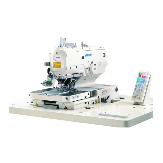
2. NAME OF EACH COMPONENT (1) Names of the sewing machine main unit 1 Temporary stop switch 7 Hand pulley 2 Presser switch 8 Machine head 3 Start switch 9 Thread stand 4 Operation panel !0 Feed base 5 Control box !1 Cloth cutting dial 6 Power switch −... -
Page 7: Structure Of The Operation Switch
3. STRUCTURE OF THE OPERATION SWITCH (1) Structure of the operation panel [Table of functions of the operation panel] Name Description Name Description Sewing LED This LED lights up when the sewing BACK key When this key is pressed, the machine can be operated. - Page 8 Description Name Name Description RIGHT “ – ” key LENGTH This key subtracts various (Taper bar This key sets sewing length length) key of taper bar. data. Note 1 Note 1 STITCHES This key sets the number of (Number RIGHT “ + ” key This key adds various data.
-
Page 9: Temporary Stop Switch
(2) Temporary stop switch This switch stops the operation of the sewing machine. Temporary stop switch (3) Hand switch 1) Presser switch (right) 1 ™ This switch performs up/down of the presser. 2) Start switch (left) 2 ™ This switch performs the start of sewing. Start switch lamp ™... -
Page 10: Standard Adjustments
4. STANDARD ADJUSTMENTS (1) Adjusting the center of the needle Standard Adjustment 1 Clearance between the needle and the left looper 0.03 to 0.1 Needle 0.03 to 0.1 Left Looper Sewing start side Eyelet buttonhole Sewing end side Straight bar side section 2 Timing between the needle and the left looper To align... - Page 11 Adjustment Procedures Results of Improper Adjustment ™ Make sure that the clearance and timing between the needle ™ Stitch skipping occurs at parallel and the looper are equal at the time of occurrence of stitch section and eyelet section at the skipping and disassembling/assembling the needle bar.
-
Page 12: Adjusting The Stitch Base Line Of The Inside Needle
(2) Adjusting the stitch base line of the inside needle Standard Adjustment (3) Adjusting the stitch bite width Standard Adjustment To align Center of rod Needle rocking amount (mm) Rocking amount Rocking amount small large Needle rocking width 2.0 to 4.0 mm −... - Page 13 Adjustment Procedures Results of Improper Adjustment 1. Remove the cloth cutting knife and plug 3. 2. Turn ON the power to the machine, press the auto key to change over to the manual operation mode, and press the ready key to set the manual state.
-
Page 14: Height Of The Needle Bar
(4) Height of the needle bar Standard Adjustment Needle bar 14.1 mm 10.8 mm To align 14.6 mm 11.3 mm (S, R, J and C types) (T type) Timing gauge marking : 32021404 Timing gauge marking : Without (5) Timing between the needle and the looper Standard Adjustment 3.3 mm Needle inside... - Page 15 Adjustment Procedures Results of Improper Adjustment ™ When the needle bar is higher 1. Remove the throat plate. Instead of the throat plate, attach timing gauge support base 1 supplied with the machine on or lower than the specified the machine. position, stitch skipping occurs 2.
-
Page 16: Clearance Between The Needle And The Looper
(6) Clearance between the needle and the looper Standard Adjustment 0.03 to 0.1 mm 0.2 mm 0 to 0.1 mm (7) Adjusting the needle guard Standard Adjustment Needle Needle inside outside 0 to 0.1mm (8) Installation positions of the spreaders and the timing to open/close the spreaders Standard Adjustment 1.Installation positions of right and left spreaders 2.Timing to open/close spreaders... - Page 17 Adjustment Procedures Results of Improper Adjustment The standard adjustment value of the clearance between the ™ When the clearance is larger needle and the looper is 0.03 to 0.1 mm. than the specified value, stitch Loosen looper setscrew 1 and adjust the clearance between skipping may occur.
-
Page 18: Adjusting The Cloth Open
(9) Adjusting the cloth open Standard Adjustment When the presser plate is open, clearance A between presser plate 8 and the corner section of feed base 9 is 1 mm. When the presser plate is closed, clearance B between presser plate 8 and the corner section of feed base 9 is 1.5 mm. - Page 19 Adjustment Procedures Results of Improper Adjustment 1. Position where the presser plate is open (Position at the time ™ If clearance A is excessively of sewing) large, needle or throat plate and 1) Loosen setscrew 5 and remove auxiliary cover 4. presser foot or eyelet holding 2) Turn ON the power and press the ready key to light up the plate will interfere with each...
-
Page 20: Adjusting The Presser
(10) Adjusting the presser Standard Adjustment (Lateral position of the presser foot) The edge of presser foot 1 is aligned with the edge of eyelet holding plate 2 (0 to 0.5 mm). (Longitudinal position of the presser foot) The arc section of presser foot 1 is aligned with the arc section of the eyelet holding plate 2. (The centers of each arc are aligned with each other.) (Inclination of the presser foot) Bottom surface of presser foot 1 should come in full contact with the knurled top surface of eyelet... - Page 21 Adjustment Procedures Results of Improper Adjustment 1. Position where the presser plate is open (position at the time of sewing) ™ When the presser is tilted, the 1) Remove presser plate 7 from the feed base. fabric is not uniformly pressed. 2) Loosen screw 4, turn presser arm 5 in the direction of arrow As a result, deformation of sewing pattern or stitch skipping...
-
Page 22: Adjusting The Lateral Position Of The Cloth Cutting Knife
Standard Adjustment 2) Adjusting the lateral position of the cloth cutting knife Adjust the knife base 2 so that the cut section in terms of the stitches at parallel section is equal on the left and right sides. 3) Adjusting the inclination of the cloth cutting knife Adjust the knife base 2 so that the cut section in terms of the stitches at parallel section is parallel. - Page 23 Adjustment Procedures Results of Improper Adjustment 2) Adjusting the lateral position of the cloth cutting knife When the lateral position of the 1. Loosen three knife base setscrews 1. cloth cutting knife is improper : 2. Adjust the position by moving knife base 2 together with knife ™...
-
Page 24: Adjusting The Knife Holder
(12) Adjusting the knife holder Standard Adjustment 1) Adjusting the longitudinal position of the knife holder Adjust the position of the knife holder 3 so that the plane A of knife holder 3 is aligned with the plane B of cloth cutting knife 5. Plane A Plane A Plane B... - Page 25 Adjustment Procedures Results of Improper Adjustment 1) Adjusting the longitudinal position of the knife holder When the longitudinal position of 1. Loosen knife stopper setscrew 1. the knife holder is improper : 2. Loosen knife fixing plate setscrew 4 and adjust so that the ™...
-
Page 26: Adjusting The Inclination Of The Knife Holder And The Backlash Of The Cloth Cutting Direct Drive Shaft
Standard Adjustment 3) Adjusting the inclination of the knife holder and the backlash of the cloth cutting direct drive shaft Adjust the inclination of the knife holder so that knife holder 3 in terms of the cloth cutting knife is parallel. - Page 27 Adjustment Procedures Results of Improper Adjustment Adjusting the inclination of the knife holder When the knife holder tilts : 1. Loosen three setscrews 1 in the cloth cutting metal. ™ Cutting the cloth at a given 2. Move cloth cutting metal 2 as the arrow mark “a” and adjust so length cannot be performed.
-
Page 28: Installing Position Of The Needle Thread Trimming Knife
(13) Installing position of the needle thread trimming knife Standard Adjustment ™S and R type (long thread trimming) Approx. 3.2 mm 1.2 to 1.5 mm Approx. 1 mm B (0.1 to 0.2 mm) (Reference) 14050009 (Right blade type) ™T type (short thread trimming without gimp) Approx. - Page 29 Adjustment Procedures Results of Improper Adjustment ™ S/R types (long thread trimming) 1. The clearance between needle thread trimming knife J 2 and the needle is approximately 1 mm. Loosen setscrew 1 and move needle thread trimming knife J 2 to adjust the clearance. 2.
- Page 30 (13) Installing position of the needle thread trimming knife Standard Adjustment ™J and C type (short thread trimming) Approx. 1 mm 1.2 to 1.5 mm − −...
- Page 31 Adjustment Procedures Results of Improper Adjustment ™ J and C type (short thread trimming) 1. The clearance between needle thread trimming knife J 2 and the needle is approximately 1 mm. Loosen setscrew 1 and move needle thread triming knife J 2 to adjust the clearance. 2.
- Page 32 (13) Installing position of the needle thread trimming knife Standard Adjustment ™Adjusting the right blade type (32023319) 0.6 to 0.75 mm Nearly align Align with line on corner section Black 32023319 14050009 Silver 32023301 When the needle thread trimming knife is Part No. 14050009, replace it with Part No.
- Page 33 Adjustment Procedures Results of Improper Adjustment ™ S type and R type (Long thread trimming) : Right blade type ™ Clearance between the top end of needle thread trimming knife 2 and the needle is 0.6 to 0.75 mm. 1. Loosen setscrew 1 in the needle thread trimming knife and move needle thread trimming knife 2 in the oblique direction to adjust the clearance.
-
Page 34: Adjusting The Needle Thread Trimming Vertical Moving Arm
(14) Adjusting the needle thread trimming vertical moving arm Standard Adjustment The vertical position of needle thread trimming vertical moving arm !5 is as follows : ™ (Initial position) When the needle thraed trimming is OFF and needle thread trimming vertical moving arm !5 is raised, clearance A of pin !7 of needle thread trimming moving arm !6 is 0.2 mm. - Page 35 Adjustment Procedures Results of Improper Adjustment 1) Adjusting the initial position When clearance A in the initial 1. Perform the adjustment in the state that the power is turned position is large : ™ Clearance B does not become OFF and the air is being supplied since the adjustment is performed in the state that needle thread trimming cylinder is small by the operating position OFF (extended).
-
Page 36: Adjusting The Looper Thread And Gimp Trimming
(15) Adjusting the looper thread and gimp trimming Standard Adjustment ™ S and R type (long thread trimming) ™ J and C type (short thread trimming) − −... - Page 37 Adjustment Procedures Results of Improper Adjustment ™ S and R type (long thread trimming) Looper thread and gimp trimming is operated at the position of the feed base origin. 1. Adjust so that looper thread and gimp are separated upward and downward by thread handling plate 1.
-
Page 38: Adjusting The Short Thread Trimming Without Gimp (T Type)
(16) Adjusting the short thread trimming without gimp (T type) Standard Adjustment 1 mm Approx. 1 mm 1 to 2 mm − −... - Page 39 Adjustment Procedures Results of Improper Adjustment 1. Adjusting the looper thread presser ™ When the clearance provided between throat plate 1 and the 1) Loosen setscrew 3. 2) Fully press downward throat plate 1 and install it. looper thread presser is smaller than the specified value, the 3) Lightly press upward the looper thread presser so that a clearance is not provided between looper thread presser 2...
-
Page 40: Adjusting The Position Of The Looper Thread Guide Plate And The Inclination Of The Counter Knife (S/R Types)
(17) Adjusting the position of the looper thread guide plate and the inclination of the counter knife (S/R types) Standard Adjustment (Position of the looper thread guide plate) When turning moving knife 3 in the direction of the arrow mark A, the slot end corner on the lower side of moving knife 3 is aligned with the corner section on the lower side of looper thread guide plate 1. - Page 41 Adjustment Procedures Results of Improper Adjustment ™ If counter knife 4 comes in one- Remove the knife cover and adjust following the procedure below. sided contact with the moving (Position of the looper thread guide plate and inclination of the knife, thread trimming failure counter knife) such as end thread remaining,...
-
Page 42: Adjusting The Looper Thread Clamp And The Thread Hauling (S/R Types)
(18) Adjusting the looper thread clamp and the thread hauling (S/R types) Standard Adjustment (Looper thread clamp) When moving knife 3 is turned in the direction of the arrow mark A, make clearance C between the top end of looper thread clamp fixing plate 6 and looper thread hauling plate 8 as small as possible (approximately 1 mm), and securely insert looper thread and gimp into the respective clamps. - Page 43 Adjustment Procedures Results of Improper Adjustment Remove the knife cover and perform adjustment following the ™ If clearance C between the top procedure described below. end of looper thread clamp fixing plate 6 and looper thread (Looper thread clamp) hauling plate 8 is excessively 1.
-
Page 44: Adjusting The Blade Pressure Of The Looper Thread Trimming Knife (S/R Types)
(19) Adjusting the blade pressure of the looper thread trimming knife (S/R types) Standard Adjustment Turn moving knife 3 in the direction of the arrow mark A, and align the top end of counter knife 4 with the periphery of moving knife when the distance from the corner of the blade section of moving knife 3 to counter knife 4 is 2 to 3 mm. - Page 45 Adjustment Procedures Results of Improper Adjustment Remove knife cover 1 and perform adjustment following the ™ I f t h e b l a d e p r e s s u r e i s procedure mentioned below. excessively high, the service life 1.
-
Page 46: Adjusting The Short Thread Trimming
(20) Adjusting the short thread trimming Standard Adjustment 1) Initial position of the lower knife The blade section of lower knife 1 aligns with the edge of holding plate, right 3. To align 2) Adjusting the stroke of the upper knife Length of the engagement of upper knife 5 and the top end of lower knife 1 is 1 to 2 mm. - Page 47 Adjustment Procedures Results of Improper Adjustment 1) Initial position of the lower knife ™ If the lower knife comes out from 1. When stopper screw B 2 is slightly loosened, it can be slided holding plate, right, the throat to the left or right since there is nut 4 in the slot on the rear of plate interferes with the lower the presser plate and stopper screw B 2 is screwed in the nut.
-
Page 48: Adjusting The Knife Pressure
Standard Adjustment 3) Adjusting the knife pressure Thread is securely trimmed, and upper knife 5 and lower knife 1 smoothly work. Especially at the time of return, the knives easily return to the initial position by the action of the spring. Knife pressure can be adjusted with fulcrum screw !0 . - Page 49 Adjustment Procedures Results of Improper Adjustment 3) Adjusting the knife pressure When the fulcrum screw is excessively 1. Loosen nut !3 on the bottom face of the presser plate. tightened : 2. Slightly tighten fulcrum screw ! 0 to the full and return it by one ™...
-
Page 50: Adjusting The Position Of The Upper Knife Lower Cover
Standard Adjustment 5) Adjusting the position of the upper knife lower cover 1. Hide the blade top of upper knife 5. (Blade top is put back by 0 to 1 mm.) 2. Slightly place the slope section to corner section E of lower knife 1. 3. - Page 51 Adjustment Procedures Results of Improper Adjustment ™ When the blade top of upper 5) Adjusting the position of the upper knife lower cover 1. Loosen two setscrews ! 1 and move upper knife lower cover ! 4 knife comes out from the upper to adjust the position.
-
Page 52: Adjusting The Needle Thread Clamp
(21) Adjusting the needle thread clamp Standard Adjustment For the assembling procedure, refer to the Instruction Manual for the needle thread clamp device. The standard adjustment value of the needle thread clamp is as described below. (The optional needle thread guide is different in shape. Refer to 4. -1). 1. - Page 53 Adjustment Procedures Results of Improper Adjustment 1. Adjust the height of top end 1 of the clamp at the time of lowering to the ™ Needle thread may not be completely material which is actually sewn, and adjust the height rather lower in the sewn in if the sewing length is short or range where the top end does not come in contact with the material.
-
Page 54: Adjusting The Length Of Remaining Needle Thread
(22) Adjusting the length of remaining needle thread Standard Adjustment It is the standard to adjust the length of remaining needle thread to a short one so that the clamped thread can be neatly rolled. The sewing machine provided with “needle thread drawing double motion function”... - Page 55 Adjustment Procedures Results of Improper Adjustment When the amount of remaining thread is desired to be further ™ When the drawing amount of shorter, loosen screws 1, and slide screws 1 in the direction of needle thread is excessively arrow mark A. small : 1.
-
Page 56: Adjusting The Haul Amount Of The Looper Thread (Long Thread Trimming/Short Thread Trimming)
(24) Adjusting the haul amount of the looper thread (long thread trimming/short thread trimming) Standard Adjustment 1. Long thread trimming type (S/R types) When looper thread haul driving arm 5 moves in the direction A, end C of looper thread haul plate 1 is almost vertical. - Page 57 Adjustment Procedures Results of Improper Adjustment 1. Long thread trimming type (S/R types) ™ Slightly increase the stroke when 1) Turn looper bracket 4 to the front. the looper thread comes out of the looper thread clamp by the moving 2) Turn ON the needle thread trimming cylinder with the test mode 2.
-
Page 58: Adjusting The Looper Thread Haul Driving Arm (Long Thread Trimming)
(25) Adjusting the looper thread haul driving arm (long thread trimming) Standard Adjustment ™ Long thread trimming type (S/R types only) − −... - Page 59 Adjustment Procedures Results of Improper Adjustment 1. Loosen setscrew 2 and fully move link B 6 to arrow mark F ™ If upward/downward clearance side (upward) (adjust the haul amount of looper thread to the of 0.5 mm is larger than the maximum).
-
Page 60: Adjusting The Remaining Amount Of The Gimp (J/C Types)
(26) Adjusting the remaining amount of the gimp (J/C types) Standard Adjustment (27) Adjusting the tension of the needle bar rotary timing belt Standard Adjustment Adjust the position of rotary tension pulley 1 and adjust the tension of needle bar rotary timing belt 4. −... - Page 61 Adjustment Procedures Results of Improper Adjustment 1. Loosen setscrew 1 to move to and fro gimp guide 2 and adjust the remaining amount of the gimp at the end of sewing. 2. To adjust, perform actual sewing on the fabric or the like and determine the position of gimp guide 2 so that the remaining length of the gimp is approximately 4 mm at the time of completion of sewing.
-
Page 62: Adjusting The Tension Of The Looper Turning Timing Belt
(28) Adjusting the tension of the looper turning timing belt Standard Adjustment Adjust the position of turning motor installing plate 2 and adjust the tension of needle bar rotary timing belt 4. (29) Adjusting the position of the needle bar rotary pulley Standard Adjustment Adjust the timing of the needle bar rotary pulley so that the clearance between the... - Page 63 Adjustment Procedures Results of Improper Adjustment 1. Loosen four setscrews 1 in the turning motor installing plate. When the tension is high : 2. Hook a spring balancer to hole 3 in turning motor installing ™ Looper bracket tilts and the plate 2 and draw the balancer with 9.8N force in the direction relation with the looper is of the arrow mark “a”.
-
Page 64: Adjusting The Position Of The Looper Bracket
(30) Adjusting the position of the looper bracket Standard Adjustment Adjust turning sensor slit 2 so that marker dot 3 engraved on the machine bed is aligned with marker dot 4 engraved on looper bracket 5 at the time of turning origin. (31) Adjusting the main shaft sensor Standard Adjustment Adjust main shaft sensor installing plate 2 so that the main shaft sensor detects at the front position... - Page 65 Adjustment Procedures Results of Improper Adjustment 1. Call Test mode No. 4 and change over to the turning axis When the marker dots are not (Pattern No. 3). (Refer to “8.-(4) Crosswise feed / lengthwise aligned with each other : feed / turning origin check”.) ™...
-
Page 66: Adjusting The Origin Position Of The Crosswise Feed Sensor
(32) Adjusting the origin position of the crosswise feed sensor Standard Adjustment 1. Remove the presser plates, left and right. 2. Turn the looper bracket by 180˚ after performing the origin retrieval referring to “8.-(4) Crosswise feed / lengthwise feed / turning origin check”. 3. - Page 67 Adjustment Procedures Results of Improper Adjustment 1. Loosen two setscrews 1 in the crosswise feed sensor installing ™ Presser foot and presser plate in the direction of the arrow mark. holding plate interfere with 2. Perform the origin retrieval and turning of the looper bracket needle and throat plate, and by 180˚...
-
Page 68: Adjusting The Cloth Cutting Origin Sensor
(34) Adjusting the cloth cutting origin sensor Standard Adjustment Adjust the cloth cutting origin sensor so that the distance between cloth cutting knife 9 and knife holder 8 should be 20 mm when the cloth cutting mechanism is in the origin sensor position. −... - Page 69 Adjustment Procedures Results of Improper Adjustment 1) Remove the presser unit, left and right. When the position of the cloth 2) Remove four side cover setscrews 1, and remove side cover cutting origin sensor is slipped : 2 and side cover packing 3. ™...
-
Page 70: Adjusting The Backlash Of The Cloth Cutting Stepping Motor
(35) Adjusting the backlash of the cloth cutting stepping motor Standard Adjustment Adjust the backlash between cloth cutting stepping motor gear 4 and cloth cutting ball screw gear 5. Minimize the backlash to such an extent that the backlash does not affect cloth cutting motor 3. Machine (36) Adjusting the cloth cutting lever stopper Standard Adjustment... - Page 71 Adjustment Procedures Results of Improper Adjustment 1. Loosen four setscrews 1 in the cloth cutting motor installing When the backlash is large : plate. ™ Operating noise is increased. 2. Move cloth cutting motor installing plate 2 in the direction of When the backlash is small : the arrow mark “a”...
-
Page 72: Adjusting The Positions Of The Lengthwise Feed And Crosswise Feed Motor Installing Bases (Adjusting The Backlash Of The Feed Drive Gear)
(37) Adjusting the positions of the lengthwise feed and crosswise feed motor installing bases (Adjusting the backlash of the feed drive gear) Standard Adjustment Adjudt the respective motor installing bases so that there is no play due to the backlash of the feed drive gear and the feed base smoothly moves when moving the feed base laterally or longitudinally by hand. - Page 73 Adjustment Procedures Results of Improper Adjustment 1. Loosen four setscrews 1, slightly press the lengthwise feed When the backlsash is large : motor in the direction of the arrow mark (/), and tighten again ™ Defective feed occurs and four setscrews 1. accuracy of needle entry 2.
-
Page 74: Adjusting The Active Tension
(39) Adjusting the active tension Standard Adjustment 1. Preparation 2. Looper thread active tension Place the groove to the upper slant left side. Thread tension shaft Thread should not be bent. 3. Needle thread active tension 4. Re-setting of the memory switch 1. - Page 75 Adjustment Procedures Results of Improper Adjustment 1. Preparation Measure the actual thread tension U and D before performing disassembling or assembling adjustment. Perform the measurement by setting needle thread tension “60”/ looper thread tension “50” and using the thread tension gauge or the like. Setting on Actual thread operation panel...
-
Page 76: Adjusting The Cloth Cutting Knife Pressure
(40) Adjusting the cloth cutting knife pressure Standard Adjustment ™ When replacing the cloth cutting knife or the knife holder, or changing the sewing material, the pressing amount of the knife or the stopping time of the knife lower position can be changed. (Caution) When the sewing machine is provided with the multicutting device, refer to “15. - Page 77 Adjustment Procedures Results of Improper Adjustment ™ Adjusting the knife pressing amount ™ Set the knife pressing amount as ] key #4 , turn ON the power. 1. Pressing [ADJUST small as possible in order to protect 2. The pressing amount set in 4-digit LED !0 is displayed. the knife and the knife holder and (30 has been set in the state of the standard delivery.) maintain the durability.
-
Page 78: Disassembly/Assembly
5. DISASSEMBLY/ASSEMBLY (1) Disassembling the needle bar driving gear Procedures of disassembling/assembling 1. Loosen setscrew !0 and pull out rock link shaft !1 . (Separation of rock link 6 and needle bar arm ! 2 ) 2. Loosen two setscrews 1 and two setscrews 3. 3. - Page 79 Cautions in assembling 1. Assemble needle bar driving gear 8 after performing the alignment of marker dots with the thread take-up lever cam. (Needle bar driving gear 8) (Caution) White painting is applied to the periphery of the tooth corresponding to the marker Alignment of dot engraved on needle bar driving gear marker dots...
-
Page 80: Disassembling The Needle Bar Arm
(2) Disassembling the needle bar arm Procedures of disassembling/assembling 1. Remove rock link shaft 1. Refer the disassembling procedure to “5.-(1) Disassembling the needle bar driving gear”. 2. Loosen two setscrews 2. 3. Loosen two setscrews 3 and two setscrews 5. 4. - Page 81 Cautions in assembling 1. Put needle bar arm thrust collars 4 and 6 between needle bar arm 7 so that there is no play in the lateral direction and fix the needle bar arm. 2. Perform the alignment of the rock link with the center of needle bar arm 7, adjust needle bar arm fulcrum shaft 8 to the left or right so that the needle bar arm smoothly moves and fix the needle bar arm.
-
Page 82: Disassembling The Cloth Cutting Mechanism
(4) Disassembling the cloth cutting mechanism Procedures of disassembling/assembling 1. Turn cloth cuttingg dial 1 to make cloth cutting lever 2 level. 2. Loosen two setscrews in thrust collar 3 and remove thrudt collar 3. 3. Remove setscrew A 4 in the cloth cutting lever, setscrew B 5 in the cloth cutting lever, setscrew A 6 in cloth cutting direct drive gear and setscrew B 7 in the cloth cutting direct drive gear. - Page 83 Cautions in assembling 1. Perform the alignment of marker dot V on cloth cutting direct drive gear 8 with marker dot W on cloth cutting direct drive metal !0 . 2. Adjust the tapered sections of setscrew A 4 in the cloth cutting lever and setscrew A 6 in cloth cutting direct drive gear to tapered holes, T and U in cloth cutting driving shaft 9 respectively.
-
Page 84: Replacing The Main Shaft Timing Belt
(6) Replacing the main shaft timing belt Procedures of disassembling/assembling 1. Remove the needle and the top cover. 2. Raise the machine head and remove the crosswise feed motor. Remove two screws 2 and 3 described in the item “(37) Adjusting the position of the lengthwise feed motor installing base”. - Page 85 Caution in assembling 1. Place main shaft timing belt 1 on main shaft pulley 2 in advance and return main shaft 3 in the direction of arrow mark B to assemble the timing belt. 2. After attaching C ring 4, move main shaft 3 in the direction ofarrow mark A and remove the thrust with main shaft collar 7 so that a play does not occur.
-
Page 86: Replacing The Needle Bar Rotary Upper Timing Belt
(7) Replacing the needle bar rotary upper timing belt Procedures of disassembling/assembling 1. Remove the needle and the face cover. 2. Raise the machine head, remove two setscrews 1 and two setscrews 2, and remove rotary cover 3. 3. Loosen two setscrews !5 , move rotary tension pulley !4 and loosen the tension of needle bar rotary timing belt !3 . - Page 87 Caution in assembling 1. Assemble needle bar rotary timing belt ! 3 , and assemble rotary pulley support A 5 and rotary pulley support B, left and right, 7. At this time, remove the play of needle bar rotary pulley ! 7 so that rotary torque (load) of needle bar rotary pulley !7 does not become large.
-
Page 88: Replacing The Needle Bar Rotary Lower Timing Belt
(8) Replacing the needle bar rotary lower timing belt Procedures of disassembling/assembling 1. Remove the needle. Then, pay attention to cords, oil wicks, etc., and check the state and procedure of wiring, piping before starting disassembling. 2. Raise the machine head, remove four setscrews 1 and remove looper thread AT unit 2. 3. - Page 89 Caution in assembling 1. Assemble looper rotary timing belt 5 and assemble looper driving arm !4 . When inserting or drawing out fulcrum shaft !1 , make thrust washer !8 come in contact with boss section !2 of the machine bed and remove the play with thrust collar ! 7 .
-
Page 90: Disassembling The Marking Light
(9) Disassembling the marking light Procedures of disassembling/assembling 1. Insert laser marking projector 1 into marking light installing base 2 and temporarily tighten it with laser marking projector setscrews 3. 2. Temporarily set marking light installing base 2 to marking light installing plate 4 with marking light installing base setscrews 5 and marking light installing base washers 6. - Page 91 Caution in assembling 1. The marking light cannot be installed to RS and RD types. 2. Do not watch directly the beam of laser marking projector 1. 3. Adjust so that the top end of laser marking projector 1 should protrude approximately 13.5 mm from marking light installing base 2.
-
Page 92: Fine Adjustment Of The Laser Marking Projector
(9) Disassembling the marking light Procedures of disassembling/assembling 1. Insert 24-6V converter ! 1 into converter installing plate ! 2 and fix it with 24-6V converter setscrews ! 3 . 2. Fix converter installing plate !2 to an optional place to the bottom side of the mchine table with converter installing plate setscrew !4 . - Page 93 Caution in assembling Adjustment Procedures Results of Improper Adjustment 1. Loosen two laser marking projector setscrews 3. ™ When the light axis of laser 2. Turn laser marking projector 1 in the direction of arrow mark beam is slipped : and adjust it so that the laser beam should be vertical to to the 1.
-
Page 94: Adjusting The Lateral Direction Of The Laser Marking Projector
Standard Adjustment 2) Adjusting the lateral direction of the laser marking projector Adjust the marking light installing base 2 so that the laser beam coming out from the laser marking projector lights on the center of needle. 3) Adjusting the irradiating range of the laser beam Adjust the position of the marking light installing plate 4 and the protruding amount of the laser marking projector 1 so that the laser beam reaches the origin position being used. - Page 95 Adjustment Procedures Results of Improper Adjustment 1. Loosen two marking light installing base setscrews 5. ™ When the laser beam is laterally 2. Move marking light installing base 2 in the direction of arrow slipped : mark and adjust it so that the laser beam lights on the center of 1.
-
Page 96: Replacing The Presser Set
(11) Replacing the presser set Procedures of disassembling/assembling For the optional presser sets, three kinds of S, M, and L are prepared according to the sewing length. Replace 1 to 4 as shown in the figure below which are included in the optional presser sets and change the position of knife unit 9, upper knife lower cover ! 1 , knife installing plate ! 2 and knife cover ! 3 . - Page 97 Caution in assembling 1. Cloth cutting knife 6 which can be used is up to the same length as that supplied with each presser set. In addition, sewing size (cut length + taper bar length) is as described below : 1) Presser set S : 16 to 24 mm (26 mm) 2) Presser set M : 24 to 32 mm (34 mm) 3) Presser set L : 32 to 40 mm (42 mm)
-
Page 98: Removing Procedure Of The Looper Thread Trimming Unit (When Sewing Beyond 38 Mm)
(12) Removing procedure of the looper thread trimming unit (When sewing beyond 38 mm) Procedures of disassembling/assembling For the long thread trimming (S/R) type, when sewing beyond the sewing length of 38 mm, remove the knife cover and looper thread trimming unit (looper thread trimming cannot be used.). 1. - Page 99 Adjustment Procedures Results of Improper Adjustment 1. When returning the looper thread trimming unit, apply an adequate amount of grease to the sliding section of the shaft, spring, etc. Perform the respective adjustments referring to the items of the adjustment related to the looper thread trimming. 2.
-
Page 100: Setting Procedure Of The Sewing Data
6. SETTING PROCEDURE OF THE SEWING DATA The standard patterns of pattern Nos. 90 to 99 can change the sewing speed and the thread tension, however, cannot change the sewing shape. When changing the shape , it is necessary to copy the shape to another pattern No. -
Page 101: Sewing Data Setting Item
(1) Sewing data setting item (In case of the machine with multicutting device, refer to the item “15. MULTICUTTING DEVICE”.) Data No. Setting itm Setting range Description Knife No. 0 : Decorative, 1 to 6 : Eyelet Shape of knife 10 : Decorative, 11 to 16 : Eyelet 0 to 6 ... - Page 102 Setting itm Setting range Description Data No. Needle thread tension 0 to 180 Needle thread tension value (Standard of individual needle thread tension) Compensation of needle thread tension -180 to 180 Compensation value of needle thread tension at right side of at right parallel section parallel section (Difference in terms of No=40) Compensation of needle thread tension...
- Page 103 Diagram of each set value (State of sewing, i,e, state that the product is observed from the wrong side.) Kind of knife F x G Decorative buttonhole 2.1 x 3.2 2.5 x 3.8 2.9 x 4.4 3.0 x 4.6 3.2 x 5.4 2.7 x 5.1 Decorative buttonhole Eyelet...
- Page 104 Length of straight bsr Number of stitches of straight bar Overlapping width of straight bar Compensation of stitch bite width of straight bar Select the combination Nos. described in the table below for the shape of the straight bar. M, N Data of the straight bar Length Number of...
-
Page 105: Compensation Of The Data
1) Compensation of the data 1) Confirm that sewing LED 1 has gone out. When the LED lights up, press [READY ] key 2 to make it go out. 2) Display the pattern No. desired to be changed. ] key !4 to display the data. 3) Press [DATA ] key 9 or [LEFT ] key 8 to... -
Page 106: Compensation Table
1 Compensation table No.8 No. 9 No. 10 No. 11 Compensation of knife Compensation of number of Compensation of turning Compensation of turning at position stirches at sewing end parallel section – – – – No. 13 No. 14 No. 15 No. -
Page 107: Thread Tension Compensation Table
2 Thread tension compensation table [ Setting of needle thread tension ] Compensation Setting item Description position No. Needle thread tension Needle thread tension value Compensation of needle thread tension of Compensation value of needle thread tension of right parallel section right side of parallel section Compensation of needle thread tension of Compensation value of needle thread tension of... - Page 108 [Compensation position of taper bar] Data No. 43 Compensation of needle thread tension of top eyelet Data No. 45 Compensation of needle thread Data No. 63 Compensation of looper tension of left bottom of eyelet thread tension of top eyelet Data No.
-
Page 109: Memory Switch
7. MEMORY SWITCH (In case of the machine with multicutting device, refer to “15. MULTICUTTING DEVICE”.) (1) Setting the memory switch The memory switch mode can be set by turning ON the power while pressing READY key 2 for the user level (level 1), and turning ON the power while simultaneously pressing READY key 2 and THREAD key 4 for the service level (level 2). -
Page 110: Memory Switch List
(4) Memory switch list (In case of the machine with multicutting device, refer to “15. MULTICUTTING DEVICE”.) Function Description Standard value Setting range Unit Level Soft-start, rpm of 1st stitch (inside / outside) The rpm of 1st stitch (inside / outside) from the start 600rpm 400 to 1200 100rpm... - Page 111 Function Description Standard value Setting range Unit Level Knife motor adjustment value 0 Adjustment value 0 of number of pulses of knife 30 pulses -100 to 300 1 pulse moving at the time of cloth cutting (Knife holder No. Position where pulse can start knife motor jump feed Position of pulse of start of crosswise/ S, J, C, T types : 400 pulses 0 to 1500...
- Page 112 Function Description Standard value Setting range Unit Level TG position at sewing feed end TG position at feed end (When No. E0 is 0.) 1 to 45 Number of times of TG TG position at sewing feed center TG position at feed center (When No. E0 is 1.) S, R types : 18 1 to 45 Number of...
-
Page 113: Test Mode
8. TEST MODE ™ Starting procedure ] key 3 and [LEFT ] key 8, turn ON the power to start the test 1) Simultaneously pressing [RESET mode. When the test mode is started, the display appears in 2-digit LED 7 and 4-digit LED !0 as shown in the figure below. -
Page 114: Output Check
(2) Output check ON/OFF of the solenoid valve can be operated from the operstion panel. Checking of the operation of each unit can be operated from the operation panel. 1) Select the function No. 2. ] key 9 or [LEFT ] key 8 to select the item No. -
Page 115: Crosswise Feed / Lengthwise Feed / Turning Origin Check
(4) Crosswise feed / lengthwise feed / turning origin check This function is used when checking or adjusting the origin of crosswise feed, lengthwise feed or turning. 1) Select the function No. 4. ] key 2 to perform the origin retrieval and returning to needle UP 2) After starting the check mode, press [READY position, and enter the operation mode. -
Page 116: Sewing Machine Check
(6) Sewing machine check Checking of the signals of the number of revolutions of the sewing machine or the main shaft can be operated and checked from the operation panel. 1) Select the function No. 6. ] key 2 to perform the origin retrieval and returning to 2) After starting the check mode, press [READY needle UP position, and enter the operation mode. -
Page 117: Error List
9. ERROR LIST DescriptionHow to reset How to reset Sewing machine motor error Turn OFF the power. Sewing machine motor doses not run or signal does not enter even when it is running. Looper thread trimming knife return error Remove the cause of error and press the RESET key. When the looper thread trimming knife has not returned at the timre of operation of the sewing machine or operation of looper thread trimming... -
Page 118: Replacing The Fuse
2. Set the data within the range below. Sewing speed – (minus) eyelet reduced speed Number of stitches of slant taper bar number of stitches of taper bar Compensation of number of stitches of right taper bar number of stitches of taper bar –14 compensation of turning + compensation of turning at parallel section –1.2... -
Page 119: Changing The Voltage
11. CHANGING THE VOLTAGE (1) Changing the voltage between 100 and 240V ™ When the voltage of 100V or 200V is supplied, the voltages as described in the table below can be used by changing the terminal board. Line color (black) Line color (brown) Input voltage Remarks... -
Page 120: Troubles And Corrective Measures
12. TROUBLES AND CORRECTIVE MEASURES Troubles and corrective measure with regard to sewing Phenomenon Cause Corrective measure 1. Stitch skipping (general) 1-1) The clearance between the needle and the looper varies • Adjust the center of the needle. Especially, re-check is according to the turning angle (0˚, 90˚... - Page 121 Phenomenon Cause Corrective measure 1 Approach the presser foot. (Adjust the lateral position.) 4. Stitch skipping near to top of eyelet 4-1) The clearance between the presser foot and the needle 2 Approach the opening position of presser plate to the entry point is too llarge.
- Page 122 Phenomenon Cause Corrective measure 10. The left- and right-hand sides of the 10-1) The left- and right-hand side cloth opening amounts • Adjust so that the left- and right-hand side cloth opening seam at the straight section of the are not equal. amounts are equal.
- Page 123 − −...
-
Page 124: Air Piping Diagram
13. AIR PIPING DIAGRAM − −... -
Page 125: Circuit Diagram
14. CIRCUIT DIAGRAM (1) Connector circuit board wiring diagram CN67 : Looper thread trimming sensor cable asm. Part No. : 32078354 CN77 : Head sensor relay cord asm. Part No. : 32077950 CN63 : Turning origin sensor asm. Part No. : 32077059 CN78 : Main shaft sensor cable asm. -
Page 126: Block Diagram (1) 1 / 2
(3) Block diagram (1) 1 / 2 − −... - Page 127 (3) Block diagram (1) 2 / 2 Part No. Description Remarks M8501620AA0 Control box A asm. M8510620AA0 Operation box A asm. M8601620AA0 MAIN circuit board A asm. M8620600AAB PWR circuit board AB asm. M8610610AAB SDC circuit board AB asm. M86026200A0 CONNECTOR circuit board asm.
-
Page 128: Block Diagram (2) 1 / 2
(4) Block diagram (2) 1 / 2 − −... - Page 129 (4) Block diagram (2) 2 / 2 Part No. Description Remarks M8501620BA0 Control box B asm. M8510620BA0 Operation box B asm. M8601620AA0 MAIN circuit board A asm. M8620600BAB PWR circuit board BB asm. M8610610AAB SDC circuit board AB asm. M86026200A0 CONNECTOR circuit board asm.
-
Page 130: Block Diagram (3) 1 / 2
(5) Block diagram (3) 1 / 2 − −... - Page 131 (5) Block diagram (3) 2 / 2 Part No. Description Remarks M8501620CA0 Control box C asm. M8510620BA0 Operation box B asm. M8601620AA0 MAIN circuit board A asm. M8620600BAB PWR circuit board BB asm. M8610610AAB SDC circuit board AB asm. M86026200A0 CONNECTOR circuit board asm.
-
Page 132: Stepping Motor Circuit Diagram
(6) Stepping motor circuit diagram − −... -
Page 133: Sensor Circuit Diagram
(7) Sensor circuit diagram − −... -
Page 134: Power Source Circuit Diagram 100V, 200V
(8) Power source circuit diagram 100V, 200V − −... -
Page 135: Power Source Circuit Diagram 380V
(9) Power source circuit diagram 380V − −... -
Page 136: Solenoid Valve Curcuit Diagram
(10) Solenoid valve curcuit diagram − −... -
Page 137: Active Tension Curcuit Diagram
(11) Active tension curcuit diagram − −... -
Page 138: Servo Motor Circuit Diagram
(12) Servo motor circuit diagram − −... -
Page 139: Multicutting Device
15. MULTICUTTING DEVICE CONTENTS (1) SPECIFICATIONS ...................... 136 (2) INSTALLING THE MULTICUTTING DEVICE ............138 1) Removing the cloth cutting knife base ..................138 2) Installing the cloth chip suction device asm................138 3) Installing the cloth cutting knife base A asm................140 4) Changing the position of the knife stopper .................. -
Page 140: Specifications
DO x 558 #90 to 110 Safety device Temporary stop switch and automatic stop function at the time of detection of trouble Lubricating oil JUKI New Defrix Oil No. 2 (Equivalent to ISO VG32) Air pressure 0.49 Mpa Air consumption... - Page 141 ■ Without looper thread trimmer (Memory switch No. 22 = 0) Max. stitch length Knife holder length (mm) Eyelet buttonhole (mm) Decorative buttonhole (mm) * Min. stitch length is the same as that with looper thread trimmer. Caution 2. Be sure to use the knife holders exclusive for the multicutting device (32087801, 32087702, 32087603, 32088106, 32088007 and 32087900).
-
Page 142: Installing The Multicutting Device
(2) Installing the multicutting device Standard Adjustment 1) Removing the cloth cutting knife base Cut 1 mm. 26 mm 2) Installing the cloth chip suction device asm. − −... - Page 143 Adjustment Procedures Results of Improper Adjustment 1) Removing the cloth cutting knife base (Remove the hose of the cloth chip chute connected to the base.) * Check the base since there are a new and an old parts. Further, in case of the old part, replace it with a new part. Refer to “15 - (2) -4) Changing the position of the knife stopper”.
-
Page 144: Installing The Cloth Cutting Knife Base A Asm
Standard Adjustment 3) Installing the cloth cutting knife base A asm. − −... - Page 145 Adjustment Procedures Results of Improper Adjustment 3) Installing the cloth cutting knife base A asm. 1. Loosen two setscrews 8 and remove cloth cutting knife (eyelet) and cloth cutting knife (straight) from the device. (Refer to “7. REPLACING THE CLOTH CUTTING KNIFE”.) 2.
-
Page 146: Changing The Position Of The Knife Stopper
Standard Adjustment 4) Changing the position of the knife stopper Screw hole C Hole D Plane E Screwhole A Screwhole B To align New parts Old parts 32068900 14039408 Cloth cutting knife fixing screw Knife fixing screw 32061319 Cloth cutting knife fixing plate 32061301 32061210 Cloth cutting... - Page 147 Adjustment Procedures Results of Improper Adjustment 4) Changing the position of the knife stopper 1. Remove knife stopper 1 of knife fitting base 4, setscrew 2 and washer 3, and change from screw hole A to screw hole 2. Attach two stop plugs 5 to screw hole C so that the stop plugs do not protrude from the knife fitting plane E.
-
Page 148: Connecting The Pneumatic Components
(3) Connecting the pneumatic components Standard Adjustment 1) Piping the knife base cylinder CN80 Port A Port B − −... - Page 149 Adjustment Procedures Results of Improper Adjustment 1) Piping the knife base cylinder 1. Loosen setscrew 1 in the end block, draw end block 2 in the direction A, and draw it out from rail 3. 2. Attach three bushes supplied with the device as accessories to solenoid valve 4 and insert solenoid valve 4 into rail 3.
-
Page 150: Piping The Cloth Chip Suction Device
Standard Adjustment 2) Piping the cloth chip suction device Label No. 36 To knife base To cloth chip suction device Label No. 16 Label No. 16 To knife fitting base Label No. 16 Label No. 16 To solenoid valve − −... - Page 151 Adjustment Procedures Results of Improper Adjustment 2) Piping the cloth chip suction device 1. Remove the piping of label No. 36 (to knife base) of solenoid valve No. 6 (cloth chip blow) 1 from the end of Y joint 3. (Including speed controller 2) 2.
-
Page 152: Adjusting The Multicutting Device
(4) Adjusting the multicutting device 1) Adjusting the knife Standard Adjustment 1 Adjusting the longitudinal position of the cloth cutting knife Adjust the distance from the top of eyelet to the center of the needle bar at the time of cloth cutting to 54 mm. - Page 153 Adjustment Procedures Results of Improper Adjustment 1. Loosen setscrew 2 in the knife stopper. When the cloth cutting knife is 2. Loosen setscrew 3 in the knife fixing plate and adjust the longitudinally out of place : position of cloth cutting knife (eyelet) 4 so that the portion ™...
-
Page 154: Adjusting The Inclination Of The Cloth Cutting Knife
Standard Adjustment 3 Adjusting the inclination of the cloth cutting knife Adjust knife base $3$ so that the cutting section is parallel to the stitches of parallel section. 2) Timing between the needle and the looper Standard Adjustment 1 Adjusting the inclination of the cloth cutting knife (eyelet) Adjust knife base B 5 so that the cutting edge plane (plane Y) of cloth cutting knife (eyelet) 1 is parallel to the installing plane (plane Z) of knife base 4. - Page 155 Adjustment Procedures Results of Improper Adjustment 1. Cut off the air of the regulator. When the cloth cutting knife is 2. Loosen setscrew ! 1 in the knife fixing plate and remove cloth inclined : cutting knife (eyelet) 7. ™ In case of the cut-after knife, 3.
-
Page 156: Adjusting The Lateral Position Of Knife Holder
Standard Adjustment 2 Adjusting the lateral position of knife holder Adjust the height of cloth cutting knife (straight) 2 so that the difference in level between the cutting edge plane (plane A) of cloth cutting knife (straight) 2 and the cutting edge plane (plane B) of cloth cutting knife (eyelet) 1 is 0.03 mm or less. - Page 157 Adjustment Procedures Results of Improper Adjustment 1. Loosen setscrew 7 in the knife fixing plate and remove cloth When the difference in level cutting knife (straight) 2. between the respective cloth cutting 2. Remove cloth cutting knife base spacer A 3. knives : 3.
-
Page 158: Adjusting The Pneumatic Components
(5) Adjusting the pneumatic components Standard Adjustment 1) Adjusting the speed controller (6) Setting the DIP switch Standard Adjustment Cloth cutting type can be changed with DIP-SW 4 located on the back of machine head. DIP-SW 4 Cloth cutting type Standard Multicutting −... - Page 159 Adjustment Procedures Results of Improper Adjustment 1) Adjusting the speed controller Adjust speed controller 1 to such an extent that there is shock when returning the cloth cutting knife (eyelet) from the tilted state. (Standard : Adjust the adjustment screw of the speed controller 1 to the open by approximately one turn from the full close.
-
Page 160: Replacing The Cloth Cutting Knife
(7) Replacing the cloth cutting knife Standard Adjustment 1) Replacing the cloth cutting knife (eyelet) 2) Replacing the cloth cutting knife (straight) d’ − −... - Page 161 Adjustment Procedures Results of Improper Adjustment ™ When setscrew 3 is excessively 1) Replacing the cloth cutting knife (eyelet) 1. Loosen setscrew 3 and remove cloth cutting knife (eyelet) 1. tightened, cloth cutting knife 2. Press the knife you desire to replace to stopper 5 and tighten (eyelet) 1 may be broken.
-
Page 162: Adjusting The Cloth Cutting Knife Pressure
(refer to Instruction Manual for MEB-3200). ™ Perform the change of set value after fully performing checking of the knife holder face and the knife. - Page 163 No. 40. (Refer to “10.-(8) Setting the pattern data of cloth cutting knife pressing amount” of the Instruction Manual for MEB-3200.) At this time, the display of panel is as shown in b. 1 and 2.
-
Page 164: Setting The Pattern Data
(9) Setting the pattern data Standard Adjustment 1) Setting the knife No. : Standard) a x b 2.1 x 3.2 2..5 x 3.8 2.9 x 4.4 3.0 x 4.6 13 or 16 ... Eyelet 3.2 x 5.4 (Setting : 11 to 16) 2.7 x 5.1 2) Cut length compensation Length... - Page 165 Adjustment Procedures Results of Improper Adjustment 1) Setting the knife No. 1. Set the knife No. of the same form as that of the knife mounted on the sewing machine and determine the multicutting operation. key ! 1 or RIGHT key ! 2 .
-
Page 166: Plural Times Selection
Standard Adjustment 3) Plural times selection 0 : Eyelet buttonhole 1 : Decorative buttonhole 2 : Eyelet buttonhole 3 : Eyelet buttonhole only Shape of the knife holder : Without step Shape of the knife holder : With step (Parts No. 32087603, 32087702, 32087801) (Parts No. - Page 167 Adjustment Procedures Results of Improper Adjustment 3) Plural times selection 1. Set the operation pattern of the cloth cutting knife. key ! 1 or RIGHT 2. The pattern can be set with RIGHT key ! 2 . When using knife holder without step : 0 or 1 When using knife holder with step : 1, 2 or 3 [In case of using the knife holder with step, the knife operation...
-
Page 168: Decorative Buttonhole Offset
Standard Adjustment 4) Decorative buttonhole offset Clearance (10) Memory switch Standard Adjustment Setting place of memory switch Nos. H9 to J6 Remainder Knife length length 1st time [I1, I4, I7, J0, (Knife holder J3, J6] length) [H9, I2, I5, I8, Knife length : Provided as standard) J1, J4]... - Page 169 Adjustment Procedures Results of Improper Adjustment 4) Decorative buttonhole offset 1. Clearance from the top of the stitches of decorative buttonhole to the cutting position can be set. key ! 1 or RIGHT 2. Set the clearance with RIGHT ! 2 . The clearance can be set in increments of 1 mm up to 0 (cut length - knife holder length - cut length compensation value).
- Page 170 Memory switch Function Description Standard Setting range Unit Level value Knife holder No. Pattern 0 : Setting knife holder No. to pattern data 0 to 1 – setting acceptable unacceptable 1 : Setting acceptable Knife adjustment value 1 Knife adjustment value 1 Adjustment value 1 of –100 to 300 Pulse number of pulses of knife moving at the time of...
- Page 171 Function Description Standard Setting range Unit Level value Plural times knife 13, knife 2nd time knife length of knife No. 13 5 to 38 length 2nd time Plural times knife 13, Remainder cut length between eyelet and 0 to 20 remainder cut amount parallel section of knife No.
-
Page 172: Replacement Gauge
(11) Replacement gauge Knife holder (For both eyelet and decorative buttonhole) ( : Provided as standard, No mark : optional) Max. sewing length (mm) Min. sewing length (mm) Sewing type Length of S h a p e o f knife holder Part No. - Page 173 * The description covered in this engineer's manual is subject to change for improvement of the TELEX : J22967 commodity without notice. Copyright C 2000-2003 JUKI CORPORATION. All rights reserved throughout the world. 03 · 02 Printed in Japan (E)
Need help?
Do you have a question about the MEB-3200 and is the answer not in the manual?
Questions and answers