Table of Contents
Advertisement
Please dispose of packaging for the product in a responsible
Professional
manner. It is suitable
for recycling.
Help to protect the
environment, take the packaging to the local amenity tip and
place into the appropriate recycling bin.
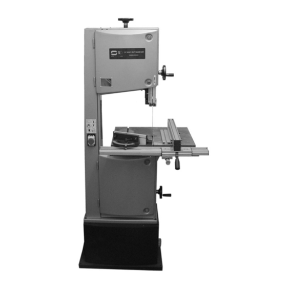
14" Wood-cutting
Never dispose of electrical equipment or batteries in with
Bandsaw
your domestic waste. If your supplier offers a disposal facil-
ity please use it or alternatively use a recognised re-cycling
agent. This will allow the recycling of raw materials and help
protect the environment.
FOR HELP OR ADVISE ON THIS PRODUCT PLEASE CALL OUR
CUSTOMER SERVICE HELP LINE : 01509 500359
Please read and fully understand the instructions in this
manual before operation. Keep this manual safe for future
Ref: 060420
reference
40
1
Advertisement
Table of Contents

Related Manuals for SIP 01444


Summary of Contents for SIP 01444
- Page 1 Please dispose of packaging for the product in a responsible Professional manner. It is suitable for recycling. Help to protect the environment, take the packaging to the local amenity tip and place into the appropriate recycling bin. 14” Wood-cutting Never dispose of electrical equipment or batteries in with Bandsaw your domestic waste.
- Page 2 GELDERS HALL ROAD SHEPSHED LOUGHBOROUGH LEICESTERSHIRE LE12 9NH Declare that the SIP 14” Pro Wood Cutting Band saw SIP Pt No: 01444 Complies with the following EEC Directives their supporting Statutory Instruments and the relevant standard where applicable: 98/37/EEC Machinery Directive 73/23/EEC...
-
Page 3: Table Of Contents
CONTENTS SIP Pro wheel kit (SIP part no. 06920): The wheel kit allows the saw to be effortlessly moved from point to point, The same kit also fits most of the other SIP Pro woodworking products. Page No. Description Contents... -
Page 4: General Safety Instructions
Read all these instructions before operating the tool and save this user manual for fu- ture reference. SIP recommends that this tool should not be modified or used for any application other than that for which it was designed. If you are unsure of its relative applications do not hesitate to contact us using the telephone number on the back of this user manual, and we will be more than happy to advise you. - Page 5 PARTS LIST….cont GENERAL SAFETY INSTRUCTIONS….cont NEVER LEAVE THE TOOL RUNNING / CONNECTED WHILST UNATTENDED: Ref. Description Ref. Description Turn off the tool and disconnect it from the mains supply between jobs. Do not leave machine until it comes to a complete stop. 316.
-
Page 6: Specific Safety Instructions
SPECIFIC SAFETY INSTRUCTIONS PARTS LIST….cont 1. Some wood and wood type products, especially MDF (Medium Density Fibreboard) Ref. Description Ref. Description can produce dust that can be hazardous to your health. We recommend the use of an 113. Flower screw & shaft, lower guide 220. Grounding terminal approved face mask with replaceable filters when using this machine in addition to us- ing the dust extraction facility. - Page 7 PARTS LIST….cont SPECIFIC SAFETY INSTRUCTIONS….cont 22. Do not modify the saw to do tasks other than those intended. Ref. Description Ref. Description 23. Keep the site free of tripping hazards. Ensure adequate lighting conditions. Saw blade Hex nut MI6 24. The saw must only be operated with all correctly mounted guards etc. 25.
-
Page 8: Safety Symbols
SAFETY SYMBOLS PARTS LIST Ref. Description Ref. Description When using the saw always ensure the operator as well as those in the Allen bolt M6 x 20 Set collar, worm area wear ear protection. Eccentric shaft Worm Base, eccentric Insert, upper guide Tyre Gear, upper guide When using the saw always ensure the operator as well as those in the... -
Page 9: Safety Devices
EXPLODED DRAWING (C) SAFETY DEVICES Blade guide: The blade guide guides the blade safely and accurately, it also covers it to reduce the risk of operator injury. The blade guide should be set so that it sits just above the work-piece during the cutting operation. -
Page 10: Technical Specifications
TECHNICAL SPECIFICATIONS EXPLODED DRAWING (B) Part number 01444 Input voltage 230v ~ 50hz Power 1500 watts (2 hp) Minimum speed (no load) 8m/sec. Maximum speed (no load) 14m/sec. Blade length 2750 mm Blade width 6 mm-25 mm Maximum work-piece height... - Page 11 EXPLODED DRAWING (A) GETTING THE KNOW YOUR BAND SAW See page 12 for descriptions...
-
Page 12: Getting To Know Your Band Saw
GETTING THE KNOW YOUR BAND SAW….cont TROUBLESHOOTING….cont Ref. Description Ref. Description Problem Possible Cause Remedy Blade Tension Fine Adjustment Rip Fence Sawdust builds up inside • • This is normal. Regularly clean out the machine: Hand-wheel sawdust from all areas of the saw. - Page 13 The machine does not work • • Damaged mains lead. Check the cable for This SIP “Pro” band saw is fitted with a standard 230v ~ plug. Before using the tool when switched on: • damage. Problem with the elec- inspect the cable and plug to ensure that neither are damaged.
-
Page 14: Assembly Instructions
ASSEMBLY INSTRUCTIONS MAINTENANCE….cont Assembling the cabinet stand: • Place the new drive belt over the pulley on the main drive-wheel. • Re-fit the drive-wheel to the saw and fully tighten the lock nut to secure. • Follow the instructions on pages 17 and 19 to re-fit the blade and to re-tension the drive belt. - Page 15 MAINTENANCE ASSEMBLY INSTRUCTIONS….cont Ref. No. Description Ref. No. Description Caution! Before carrying out any maintenance, ensure that the band-saw is turned off and that the plug is removed from the mains supply. 371. Bottom Panel 379. Rear panel 372. Bolt M8 x 16 380.
- Page 16 ASSEMBLY INSTRUCTIONS….cont OPERATING INSTRUCTIONS….cont Fitting the locking bolt to the door: • With the power supply still disconnected rotate the blade wheel by hand ensur- ing that the blade does not catch on the guides, re-set as necessary. • Screw 1 x M6 nut approximately half way up the M6 x 20 Allen bolt. •...
- Page 17 OPERATING INSTRUCTIONS….cont ASSEMBLY INSTRUCTIONS….cont Upper guide: This machine is supplied partly assembled, Prior to use, the following items need to be fitted to the band saw: The lateral support bearings should be set so that they are approximately 0.5 mm away from the blade.
- Page 18 ASSEMBLY INSTRUCTIONS….cont OPERATING INSTRUCTIONS….cont Caution: Always ensure that the saw is turned off and that the mains lead is removed from the power supply before carrying out any adjustments or maintenance. Tilting the table to perform bevel cuts: • loosen the table tilt locking lever (T). •...
- Page 19 OPERATING INSTRUCTIONS….cont ASSEMBLY INSTRUCTIONS….cont • Line the cut-outs on the fence guide with the thumbscrews earlier fitted to the Changing the blade speed: bottom of the main table. • Release the belt tension fully by turning the belt tension hand-wheel anti- clockwise.
-
Page 20: Operating Instructions
OPERATING INSTRUCTIONS OPERATING INSTRUCTIONS….cont Tracking the saw-blade: Changing / fitting the blade: • Release the blade tracking lock lever by turning it clockwise. • Remove the rip-fence. • Loosen the thumbscrews that secure the rip-fence rail and remove it. Blade tension fine ad- justment hand-wheel Blade tracking lock lever Blade...
Need help?
Do you have a question about the 01444 and is the answer not in the manual?
Questions and answers