Yamaha F-20 Service Manual
Hide thumbs
Also See for F-20:
- Owner's manual (7 pages) ,
- Maintenance manual (130 pages) ,
- Owner's manual (104 pages)
Advertisement
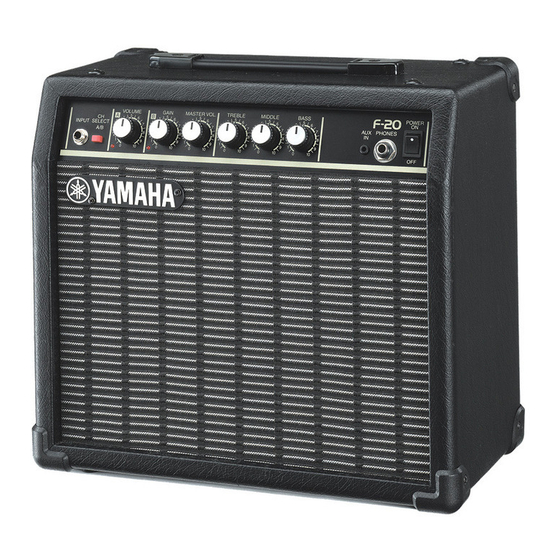
GUITAR AMPLIFIER
SERVICE MANUAL
CONTENTS
SPECIFICATIONS .............................................................................. 3
PANEL LAYOUT .................................................................................. 3
CIRCUIT BOARD LAYOUT ................................................................. 4
BLOCK DIAGRAM .............................................................................. 4
DISASSEMBLY PROCEDURE ........................................................... 5
CIRCUIT BOARDS ............................................................................. 7
IC BLOCK DIAGRAM .......................................................................... 8
INSPECTIONS .................................................................................... 8
PARTS LIST
OVERALL CIRCUIT DIAGRAM
This document is printed on chlorine free (ECF) paper with soy ink.
GA
011551
HAMAMATSU, JAPAN
1.338K-713 K
Printed in Japan 2001.09
Advertisement
Table of Contents

Related Manuals for Yamaha F-20


Summary of Contents for Yamaha F-20
- Page 1 GUITAR AMPLIFIER SERVICE MANUAL CONTENTS SPECIFICATIONS ................3 PANEL LAYOUT .................. 3 CIRCUIT BOARD LAYOUT ..............4 BLOCK DIAGRAM ................4 DISASSEMBLY PROCEDURE ............5 CIRCUIT BOARDS ................7 IC BLOCK DIAGRAM ................8 INSPECTIONS ..................8 PARTS LIST OVERALL CIRCUIT DIAGRAM This document is printed on chlorine free (ECF) paper with soy ink.
-
Page 2: Important Notice
IMPORTANT NOTICE This manual has been provided for the use of authorized Yamaha Retailers and their service personnel. It has been assumed that basic service procedures inherent to the industry, and more specifically Yamaha Products, are already known and understood by the users, and have therefore not been restated. -
Page 3: Specifications
F-20 SPECIFICATIONS Rated Output Power: Speaker: 20cm x 1 Controls: VOLUME, GAIN, MASTER VOL., TREBLE, MIDDLE, BASS, CH SELECT switch (A/B) Input/Output Terminals: INPUT, AUX IN, PHONES Output Impedance: 100Ω (PHONES) Power Consumption: 30W/100V (J) 25W/120V (UL,CSA) 25W/230V (E,BS) Power Requirements: U.S. -
Page 4: Circuit Board Layout
F-20 CIRCUIT BOARD LAYOUT Top View Side View © © AC Cord MAIN Power Transformer MAIN MAIN MAIN Front View © MAIN V695450 BLOCK DIAGRAM MAIN CH. SELECT SW CH. A CH. B CLEAN DRIVE OP AMP AUX IN +12V... -
Page 5: Disassembly Procedure
F-20 DISASSEMBLY PROCEDURE Pre-Main Unit (Time required: about 1 min) Remove the speaker wires. Remove the four (4) screws marked [30]. The pre-main unit can then be removed by sliding it backward. (Fig.1) Speaker (Time required: about 1 min) Remove the four (4) screws marked [A]. The back board can then be removed. (Fig.1) Remove the four (4) screws marked [B]. - Page 6 F-20 MAIN 2/2 Circuit Board (Time required: about 3 min) Remove the pre-main unit. (See procedure 1) Remove the screw marked [C80]. The MAIN 2/2 circuit board can then be removed. (Fig.5) Power Transformer (Time required: about 4 min) Remove the pre-main unit. (See procedure 1) While pushing down the nut marked [P70] with a spanner, remove the two (2) screws marked [P60].
-
Page 7: Circuit Boards
F-20 CIRCUIT BOARDS MAIN1/2 Circuit Board INPUT SELECT VOLUME GAIN MASTER VOLUME TREBLE to Power Transformer to Main 2/2 CN5 from Power Transformer from Power Cord FUSE VERSION INDICATION RATE J, U 250V 500mA Must be erased Must be erased... -
Page 8: Ic Block Diagram
F-20 IC BLOCK DIAGRAM BA4558 (XO078A00) Dual Operational Amplifier MAIN: IC2,IC3 +DC Voltage Output A Supply Inverting Output B Input A Non-Inverting Inverting Input B Input A Non-Inverting -DC Voltage Supply Input B INSPECTIONS Preparation To inspect the main unit, the following jigs are required. -
Page 9: Parts List
F-20 GUITAR AMPLIFIER PARTS LIST CONTENTS OVERALL ASSEMBLY .................. 2 PRE-MAIN UNIT .................... 4 ELECTRICAL PARTS ..................6 WARNING Components having special characteristics are marked and must be replaced with parts having specifications equal to those originally installed. The numbers in “QTY” shows quantities for each unit. - Page 10 F-20 OVERALL ASSEMBLY Pre-Main Unit (See P. 4) C120 C100 C110 Pre-Main Unit OVERALL CABINET ASSEMBLY Speaker Back Board...
- Page 11 F-20 PART NO. DESCRIPTION REMARKS REF NO. QTY RANK OVERALL ASSEMBLY Overall Assembly (V695390) Overall Assembly (V736090) Overall Assembly (V736100) Overall Assembly (V736110) V 6 9 5 4 6 0 0 Overall Assembly Pre-Main unit (V695450) Pre-Main unit (V736130) Pre-Main unit...
- Page 12 F-20 PRE-MAIN UNIT A100 A110 A120 A130 A140 P100 P120 P110...
- Page 13 F-20 PART NO. DESCRIPTION REMARKS REF NO. QTY RANK PRE-MAIN UNIT Pre-Main unit (V695450) Pre-Main unit (V736130) Pre-Main unit (V736140) Pre-Main unit (V736150) V6954800 Chassis V6954900 Panel Sheet Amp Kit (V733660) Amp Kit (V733670) Amp Kit (V733680) Amp Kit (V733690)
- Page 14 F-20 ELECTRICAL PARTS DESCRIPTION REMARKS PART NO. QTY RANK REF NO. ELECTRICAL PARTS V 7 3 3 7 2 0 0 Circuit Board (XZ804B0) V 7 3 3 7 3 0 0 Circuit Board (XZ804B0) V 7 3 3 7 2 0 0...
- Page 15 F-20 PART NO. DESCRIPTION REMARKS REF NO. QTY RANK HF456330 Carbon Resistor 3.3K 1/4 J HF456100 Carbon Resistor 1.0K 1/4 J HF456100 Carbon Resistor 1.0K 1/4 J HF458100 Carbon Resistor 100.0K 1/4 J HF456100 Carbon Resistor 1.0K 1/4 J HF457330 Carbon Resistor 33.0K 1/4 J...
-
Page 16: Parts List
<P.1> OVERALL CIRCUIT DIAGRAM F-20 D2SBA20 (VP344100) DIODE STACK 1.5A 200V CH SELECT A/B MAIN OP AMP OP AMP TREBLE OP AMP VOLUME AUX IN INPUT BASS OP AMP GAIN MIDDLE MASTER MAIN HIFI AMP OP AMP POWER ON/OFF OP AMP...
Need help?
Do you have a question about the F-20 and is the answer not in the manual?
Questions and answers