Table of Contents
Advertisement
Advertisement
Table of Contents

Related Manuals for Luxman L-550AXII


Summary of Contents for Luxman L-550AXII
- Page 1 INTEGRATED AMPLIFIER L-550AXII Owner`s Manual...
-
Page 2: Table Of Contents
Contents Precautions ············································································································· 1 Features of This Unit ································································································ 2 Names and Functions ······························································································ 4 Connections ·········································································································· 12 Operations ············································································································· 16 How to use Remote Control ·················································································· 18 Block Diagram ······································································································· 20 Specifications ········································································································ 21 Before Asking for Repair Services ·········································································· 22... -
Page 3: Precautions
Precautions Ⅱ INTEGRATED AMPLIFIER L-550AX Installation place Cautions in connecting speakers This unit shall be installed in a well-ventilated and effectively When making speaker system connections, exercise extra heat-released place because this unit is an A-class amplifier care not to short-circuit between ! and @ of the speaker and generates considerable heat. -
Page 4: Features Of This Unit
Features of This Unit New LECUA1000 — LUXMAN Electric High-inertia power supply Controlled Ultimate Attenuator 1000 High-inertia power supply circuit that combines a large-ca- pacity EI-core-type power transformer with original 10,000 μF New LECUA1000, which is the integration of an amplifier cir- ×... - Page 5 Ⅱ INTEGRATED AMPLIFIER L-550AX Round pattern board Large type speaker terminals After careful consideration of delicate audio signal flow, a Speaker terminals (A and B systems) of inline layout (with round pattern board has been applied to achieve smooth sig- same characteristics for right and left), which is compatible nal transmission.
-
Page 6: Names And Functions
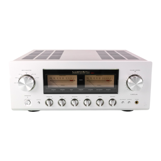
Names and Functions Front panel 1. Operation switch (OPERATION) 3. Input selector (INPUT SELECTOR) Toggles the power on and off. When wiring or connection is Selects an input device from the devices such as a CD play- performed, be sure to turn off this switch. er, an SACD player, a D/A converter, and a tuner connected to each input terminal. - Page 7 Ⅱ INTEGRATED AMPLIFIER L-550AX 5. Display window 9. Separate switch (SEPARATE) Displays the operation status of this unit. Separates the pre-amplifier and main-amplifier each other. This window is composed of 7 indicators and 2 power me- off (separate indicator off): ters.
-
Page 8: Front Panel
Names and Functions Front panel 10. Line straight switch (LINE STRAIGHT) 11. Balance control (BALANCE) Enhances the purity of the sound quality by bypassing the Adjusts the balance of sound volume between right and left balance control circuit, tone control circuit, or the like. channels. - Page 9 Ⅱ INTEGRATED AMPLIFIER L-550AX 13. Tone control for bass 16. Cartridge selection switch TONE CONTROL (BASS) (CARTRIDGE) Controls the frequency characteristics of the low-frequency Changes the gain level of the equalizer amplifier (amplifier range. circuit required to play an analog record). When this control is set to the center position, flat frequency Selects the MC (moving coil) type cartridge of characteristic is obtained.
- Page 10 Names and Functions Display window 1. Monitor indicator (MONITOR) 3. Subsonic indicator (SUBSONIC) Lights up when the monitor switch is on. Lights up when the subsonic switch is on. 2. Power meters 4. Monaural indicator (MONO) The left meter reads the output of the L channel, and the Lights up when the monaural switch is on.
- Page 11 Ⅱ INTEGRATED AMPLIFIER L-550AX 5. Standby indicator (STAND BY) 8. Line straight indicator (LINE STRAIGHT) Lights up when the AC plug is plugged into a wall socket Lights up when the line straight switch is on. and the operation switch is set to off. This indicator turns off when the AC plug is disconnected When the line straight switch is set to on, the subsonic, monaural and loudness cannot be adjusted from the ac-...
-
Page 12: Rear Panel
Names and Functions Rear panel 1. Signal ground (SIGNAL GROUND) 3. LINE-1, LINE-2, LINE-3, and LINE-4 input terminals (unbalanced) Is a ground terminal for devices to be connected to this unit. (LINE-1, LINE-2, LINE-3, and LINE-4) This terminal is used to reduce noise when other devices are connected. - Page 13 Ⅱ INTEGRATED AMPLIFIER L-550AX 5. Pre-out terminal (PRE OUT) 9. AC inlet (AC IN) This terminal is used to obtain the output of the preampli- Connects the accessory power cable. The power shall be fier section. A bi-amp connection can be performed with supplied from a household wall socket.
-
Page 14: Connections
Connections CD/SACD PLAYER D/A CONVERTER RECORDER – – – – ANALOG PLAYER SPEAKER SYSTEM ( A ) SPEAKER SYSTEM ( B ) -
Page 15: Before Connecting
Ⅱ INTEGRATED AMPLIFIER L-550AX Before Connecting How to connect CD player, SACD player, D/A converter, tuner, or other devices Before connecting other devices, connect the jack side of the accessory power cable to the AC inlet of this unit. Connect between the output terminals of a CD player, an SACD player, a D/A converter, a tuner, or other such input devices and the LINE-1 input terminals of this unit with 2 (R When connecting, turn off the power supply of this unit and... - Page 16 Connections CD/SACD PLAYER D/A CONVERTER RECORDER – – – – ANALOG PLAYER SPEAKER SYSTEM ( A ) SPEAKER SYSTEM ( B )
-
Page 17: How To Connect Recorder
Ⅱ INTEGRATED AMPLIFIER L-550AX How to connect analog record player When you need not toggle an input source to be record- Connect between the output terminals of an analog record ed (especially when a recorder connected to the recorder player and the PHONO terminals of this unit with 2 (R and output terminals is recording), do not operate this switch. -
Page 18: Operations
Operations Before operation How to operate the tone control 1. Ensure that the connections are correctly performed. This unit has the tone control function for the low-frequency (Normal playback cannot be achieved with wrong con- and high-frequency ranges. nections of R, L, !, or @) The low-frequency range type works in the 300 Hz or lower. - Page 19 Ⅱ INTEGRATED AMPLIFIER L-550AX Procedure of timer-controlled recording Memory 1. Turn on the operation switch to activate this unit. This unit stores the following items when the power is off: 2. Select a source to be recorded under timer control with Item Default the input selector.
-
Page 20: How To Use Remote Control
How to use Remote Control Remote control (RA-17A) 1. Operation switch (OPERATION) 4. Separate switch (SEPARATE) Toggles the power on and off. Separates the pre-amplifier and main-amplifier section each When wiring or connection is performed, be sure to turn off other. -
Page 21: Remote Control
Ⅱ INTEGRATED AMPLIFIER L-550AX 7. Subsonic switch (SUBSONIC) 11. Volume control switches (VOLUME, i, o) Cuts ultra-low frequencies out of audible range to pre- vent ultra-low range noise from adversely affecting audible Adjusts the sound volume. range. This function is significantly effective especially when •... -
Page 22: Block Diagram
Block Diagram RECTIFIER RECTIFIER RECTIFIER RECTIFIER RECTIFIER REG. REG. REG. -
Page 23: Specifications
Specifications Ⅱ INTEGRATED AMPLIFIER L-550AX Rated output 20 W+20 W (8 Ω) 40 W+40 W (4 Ω) Total harmonic distortion 0.007 % (8 Ω, 1 kHz both channels simultaneous drive, line straight on) 0.02 % (8 Ω, 20 to 20 kHz both channels simultaneous drive, line straight on) Pre-amplifier PHONO (MM) : 2.5 mV / 47 kΩ... -
Page 24: Before Asking For Repair Services
Before Asking for Repair Services While the unit is used, an unusual phenomenon may be confused as a malfunction for a certain reason. Prior to asking our official sole distributor of your country for repair services, please check the table below and read the operating instructions for the subsidiary devic- es. - Page 25 MEMO Ⅱ INTEGRATED AMPLIFIER L-550AX...
- Page 26 MEMO...
- Page 28 LUXMAN CORPORATION, JAPAN AG00987E52A 1-3-1 Shinyokohama, Kouhoku-ku, Yokohama-shi, Kanagawa 222-0033, Japan Printed in Japan...
Need help?
Do you have a question about the L-550AXII and is the answer not in the manual?
Questions and answers