Table of Contents
Advertisement
Advertisement
Table of Contents

Related Manuals for AEMC 6240


Summary of Contents for AEMC 6240
- Page 1 6240 MICRO-OHMMETER E N G L I S H User Manual...
- Page 2 The recommended calibration interval for this instrument is 12 months and begins on the date of receipt by the customer. For recalibration, please use our calibration services. Refer to our repair and calibration section at www.aemc.com. Serial #: ________________________________ Catalog #: 2129.80 Model #:...
-
Page 3: Table Of Contents
Table of Contents 1. INTRODUCTION ................3 1.1 International Electrical Symbols ..........4 1.2 Definition of Measurement Categories ........4 1.3 Receiving Your Shipment ............4 1.4 Ordering Information ..............5 1.4.1 Accessories and Replacement Parts ......5 2. PRODUCT FEATURES ..............6 2.1 Description ................6 2.2 Applications ................7 2.3 Key Features ................7 2.4 Control Features ...............8 2.5 Button Functions ...............9 2.6 Display Symbols ..............10 3. - Page 4 6.1 Error Messages ..............32 6.1.1 Voltage Present ............32 6.1.2 Overrange ..............33 6.1.3 Noisy Measurement ............33 6.1.4 Overheating ..............33 MAINTENANCE ................... 34 7.1 Warning...................34 7.2 Cleaning ..................34 7.3 Charging/Recharging the Battery ...........35 7.4 Battery and Fuse Replacement ..........36 Repair and Calibration ................37 Technical and Sales Assistance ............37 Limited Warranty ...................38 Warranty Repairs ...................38 Micro-Ohmmeter Model 6240...
-
Page 5: Introduction
(50V Cat. III). Use only accessories that comply with safety standards (IEC 61010-2- 031). • The test leads and measuring wires must be in good condition and should be replaced if there is any evidence of deterioration (insulation split, burnt, etc.). • Troubleshooting and metrological verification procedures must only be performed by qualified, approved personnel, or the factory. Micro-Ohmmeter Model 6240... -
Page 6: International Electrical Symbols
Cat. IV: For measurements performed at the primary electrical supply (<1000V) such as on primary overcurrent protection devices, ripple control units, or meters. Receiving Your Shipment Upon receiving your shipment, make sure that the contents are consistent with the packing list. Notify your distributor of any missing items. If the equip- ment appears to be damaged, file a claim immediately with the carrier and notify your distributor at once, giving a detailed description of any damage. Save the damaged packing container to substantiate your claim. NOTE: Charge the instrument fully before use. Micro-Ohmmeter Model 6240... -
Page 7: Ordering Information
Ordering Information Micro-ohmmeter Model 6240 ..........Cat. #2129.80 Includes set of two 10ft Kelvin clips (10A - Hippo), NiMH rechargeable battery pack, optical USB cable, US 115V power cord, one pad of measurement results forms, DataView software, extra large tool bag, two spare fuses (12.5A), product ®... -
Page 8: Product Features
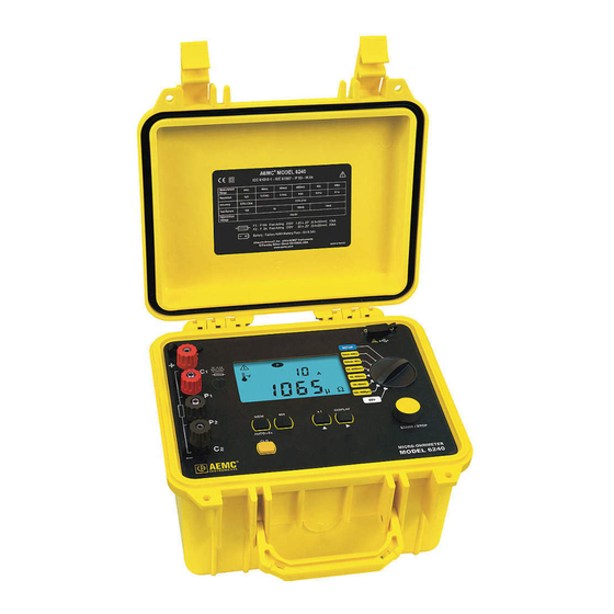
CHAPTER 2 PRODUCT FEATURES Description The Micro-ohmmeter Model 6240 is used to perform low resistance measurements from 1μΩ to 400Ω. There are six ranges with test currents from 10mA to 10A. The front end of the micro-ohmmeter employs a four-wire Kelvin configu- ration, which eliminates test lead resistance for a measurement accuracy of 0.25%. A built-in circuit filters out AC signals. The Micro-ohmmeter Model 6240 is packaged in a sealed field case well suited for shop and field use. Power is supplied by a long-life NiMH battery pack with a built-in recharger (110/220V). The large, easy-to-read liquid crystal display is 2.25 x 4.00". It displays the value of resistance, current or voltage test, polarity and battery charge. For operator safety and instrument protection, the micro-ohmmeter is fuse protected at the inputs. One fuse, accessible from the front panel, protects against stored energy in inductive loads. Enhanced internal circuitry protects against possible inductive kickback when the current is shut off. A built-in thermal switch protects the micro-ohmmeter against overheating on the 10A range when in continuous use. -
Page 9: Applications
Ω to 400Ω • Test current selection from 10mA to 10A • Manual temperature compensation (with DataView software) ® • Front panel polarity reverse function • Stores up to 99 test results • Operator safety by automatic discharge of residual charge on the equipment under test • Instantaneous, continuous or multiple test operation • Auto store of multiple test results • Internal, rechargeable batteries conduct up to 850, 10A tests • A built-in battery pack recharger recharges the batteries by connecting to the AC line (110V-230V, 50/60Hz) using a standard line cord • 4-Wire measurement with automatic compensation of undesirable voltages and lead resistance • Large multi-function backlit display • Direct display of the measurement with units, range and test current • Rugged, sealed case Micro-Ohmmeter Model 6240... -
Page 10: Control Features
Control Features MEMMRCLR °C°F ° HOLD OBJ. TEST > < µmΩ Figure 2-1 1. Kelvin input terminals 2. AC line recharging receptacle 3. Output fuse - 12.5A, 500V, 6x32mm 4. Large multi-line backlit liquid crystal display (see § 2.6) 5. Optical interface connector for connection to a computer 6. Range selection switch 7. Start/Stop button 8. Program/function buttons (see § 2.5) Micro-Ohmmeter Model 6240... -
Page 11: Button Functions
Displays the current or voltage on the terminals. AUTO>2s Activates automatic recordings. Used in the SET-UP and memory mode, selects a function or incre- ments a flashing parameter. Used in the SET-UP and memory mode, accesses the function to be modified. Erases the memory Micro-Ohmmeter Model 6240... -
Page 12: Display Symbols
Indicates that a measurement has been stopped First position locator for data stored in memory OBJ. Second position locator for data stored in memory TEST Not used °C / °F Memory utilization indicator R (+I) + R (-I) Displays average Not used Indicates an overrange > Micro-Ohmmeter Model 6240... -
Page 13: Specifications
40.0 to 0.40 to 4.0 to Range 3.999mV 39.99mV 399.9mV 3.999V 4.70V Resolution 1µV 10µV 100µV 10mV CURRENT MEASUREMENT INDICATION Measurement 5.0 to 40.0 to 0.40 to 4.0 to Range 39.99mA 399.9mA 3.999A 11.00A Resolution 10µA 100µA 10mA Micro-Ohmmeter Model 6240... -
Page 14: Mechanical
Battery Life: Range dependent Range Number of measurements* 3500 100mA 4500 10mA 5000 In Standby or Off battery life 4 to 6 months *Established for measurements lasting 5s, every 25s. Mechanical Dimensions: 10.70 x 9.76 x 7.17" (272 x 248 x 182mm) Weight: 10 lbs (4.5kg approx) Case Protection: ABS plastic polycarbonate: watertight to IP54 (cover closed), water resistant to IP53 (cover open). Color: Safety yellow case with gray faceplate Micro-Ohmmeter Model 6240... -
Page 15: Environmental
For short-term storage (1 month) the temperature can reach up to 122°F (50°C). Safety Electrical safety as per EN 61010-1 (Ed. 2 of 2001), EN 61557 (Ed. 97) parts 1 and 4. Degree of pollution: 2 Protection: Measurement Cat. III, 50V with respect to earth, 500V differ- ential between terminals, and 300V Cat. II on the charger input Electromagnetic Compatibility: The instrument satisfies the CEM and DBT directives required for the CE marking and product standard EN 61326-1 (Ed. 97) + A1 (Ed. 98) Emissions in residential environment Immunity in industrial environment *All specifications are subject to change without notice Micro-Ohmmeter Model 6240... -
Page 16: Operation
Instrument Configuration (SET-UP mode) The SET-UP mode is used to modify the instrument’s configuration. This can also be performed by using the DataView ® software that came with the instrument (see § 5). To configure the Model 6240 directly from the display, turn the rotary switch to the SET-UP position. The following screen will appear: • The display order of the parameters that can be modified is: Clear all memory (see § 4.9.2) Time Date - Automatic Power Off - Display of the Internal Parameters (e.g. serial number, software version, date of last calibration, lighting of all segments on display) Micro-Ohmmeter Model 6240... -
Page 17: Resistance Measurements
The range selection may be changed while the instrument is on. HOLD 5. Press the START/STOP button again to stop the measurement or disconnect one of the Kelvin clips. The last measurement made is displayed along with the symbol. Micro-Ohmmeter Model 6240... -
Page 18: Measurement Readings
4.3.2 Connections and Readings The Model 6240 generates a current (I) from the internal voltage source (V). A voltmeter measures the voltage drop at the Kelvin probe contact points to the resistance to be measured (R ) and... -
Page 19: Test Lead Connection
3. Connect the clips to the second object. The measurement restarts automatically. Repeat as necessary. 4. After the last measurement, press START/STOP again. NOTE: This operation is valid only if all of the objects to be measured have substantially the same value and all of the measurements are made in the same range. Micro-Ohmmeter Model 6240... -
Page 20: Measuring Very Low Resistance
Measuring Very Low Resistance When measuring very low resistive values in the µΩ range, the presence of stray DC currents may affect the accuracy of the measurements. These currents can be present due to a variety of reasons including chemical or thermal EMF in samples made of dissimilar metals. You can eliminate the effects of this by reversing the direction of current flow (see example below) and using the average of forward and reverse readings. The presence of AC interference in the sample under test may cause the measured value on the display to fluctuate. This interference may become more noticeable in the presence of strong electric fields. The effects of this interference may be reduced by twisting the leads around each other. 1. Reverse the direction of the current by pressing the ±I button and the instrument displays the average: R(+I) + R(-I) 2. To display the values R(+I) and R(-I), press the DISPLAY button. HOLD R(+I) R(+I) R(-I) R(-I) µ Ω Press the DISPLAY button to cycle through the values Micro-Ohmmeter Model 6240... -
Page 21: Automatic Recording
Use the arrow buttons to change the values of the OBJ and TEST OBJ. TEST > 2s When finished, press the MEM button for >2s 5. Press the START/STOP button to begin measuring. At each new measurement, the test number is incremented and the measurement is recorded. 6. Press the START/STOP button again to stop automatic recording. HOLD OBJ. TEST µ Ω Micro-Ohmmeter Model 6240... -
Page 22: Storing Results Into Memory
TEST option, then use the button to change the number of the test or object. 5. When finished, press the MEM button for >2s. The measurement is stored. Use the arrow buttons to change the values of the OBJ and TEST OBJ. TEST > 2s When finished, press the MEM button for >2s 6. If the user selects a memory address that is already occupied, appears on the main screen. To overwrite the location, press the MEM button for >2s. Micro-Ohmmeter Model 6240... -
Page 23: Recalling Results From Memory
Exits without Memory Recording Display shown if memory is full: Display shown If memory is empty: OBJ. OBJ. TEST TEST Recalling Results from Memory 1. Make sure there is no measurement in progress. 2. Press the MR button. 3. Use the buttons to select the desired OBJ and TEST. 4. Press the MR button again to exit the memory function. Use the arrow buttons to change the values of the OBJ and TEST Micro-Ohmmeter Model 6240... -
Page 24: Erasing Measurements From Memory
OBJ and TEST OBJ. TEST OBJ. TEST > 2s µ Ω When finished, press the CLR button for > 2s 4.9.2 Erasing All Measurements 1. Turn the rotary switch to Set-up. The default display appears: 2. Press for >2s. will blink. 3. Press will display. again. 4. Press again for >2s. All measurements are erased and the screen returns to the default display. Micro-Ohmmeter Model 6240... -
Page 25: Dataview ® Software
CHAPTER 5 DATAVIEW SOFTWARE ® Introduction The DataView software, supplied with the Micro-Ohmmeter Model 6240, ® provides the following functions: 1. The ability to configure the micro-ohmmeter from the computer. 2. The ability to store test results and print out reports of any test. NOTE: DataView cannot be used to start/stop a test or change ranges. - Page 26 Help menu. ® • - The MetaViewer utility program allows a user to MetaViewer view and print .dmf or .emf files generated by DataView without ® having DataView software installed. ® • Software Updates - Links to the AEMC Software Update ® website to check for new software version releases. Micro-Ohmmeter Model 6240...
- Page 27 • Firmware Upgrades - Links to the AEMC Firmware Upgrade ® website to check for new firmware version releases. • - Shows a list of instrument related documents Documents that you can view. Adobe Reader is required for viewing PDF ® documents supplied with DataView ® 3. DataView, Version x.xx.xxxx option should be selected by default. Select the desired language and then click on Install.
- Page 28 12. When the drivers are finished installing, the Installation Successful dialog box will appear. Click on OK. 13. Next, the Installation Wizard Complete window will appear. Click on Finish. 14. A Question dialog box appears next. Click Yes to read the procedure for connecting the instrument to the USB port on the computer. NOTE: The Set-up window remains open. You may now select another option to download (e.g. Adobe Reader), or close the window. ® 15. Restart your computer, then connect the instrument to the USB port on the computer. Micro-Ohmmeter Model 6240...
-
Page 29: Connecting The Instrument To Your Computer
Add/Remove Hardware utility to remove the instrument driver before repeating the process. Connecting the Instrument to your Computer The Model 6240 is supplied with a USB interface cable (Cat. #2135.41) necessary for connecting the instrument to the computer. This cable is... -
Page 30: Opening The Micro-Ohmmeter Control Panel
Double-click the Micro-ohmmeter Icon that was created during installation, located on the desktop. The Micro-ohmmeter Control Panel will open. Figure 5-5 To establish a communication link with the instrument, go to Instrument > Connect in the main menu. The Communication dialog box will appear. Make sure that the communication port displayed in the dialog box matches the port that the serial cable is plugged into. Figure 5-6 Once the proper communication parameters have been speci- fied, click OK. Micro-Ohmmeter Model 6240... -
Page 31: Configuring The Instrument
• Programs the micro-ohmmeter using the Write to Instrument: current settings. • Reads the current configuration of the Read from Instrument: micro-ohmmeter attached via the communications cable. • Closes the Configuration dialog box and brings up the Cancel: Control Panel. Once all of the fields have been configured, click on the Write to Instrument button to configure the instrument and close the Configuration dialog box. Micro-Ohmmeter Model 6240... -
Page 32: Downloading Stored Tests
1. Select the download command (either from the Instrument menu or the Download button). 2. The software will build a list of tests stored in the instrument and the Select Tests dialog box will appear, allowing you to select which tests to download. Figure 5-10 3. Highlight the desired tests using the Shift or Ctrl keys and select the Download button. NOTE: For additional help on using the software, use DataView’s “Help” Menu, which is located on the menu bar. Micro-Ohmmeter Model 6240... -
Page 33: Saving/Exporting Data To A Spreadsheet Or Pdf File
Exporting Data to a PDF from DataView ® To export data to a PDF file: With a database open, go to File > Generate PDF. In the Print dialog box that appears, make sure that PDF- XChange 3.0 is selected from the drop-down menu, then click When the PDF is complete, the Save As dialog box will appear. Choose a location to save it to and click Save. NOTE: Data can also be exported to a spreadsheet from within DataView by going to File > Export to Spreadsheet. Micro-Ohmmeter Model 6240... -
Page 34: Troubleshooting
CHAPTER 6 TROUBLESHOOTING Error Messages 6.1.1 Voltage Present An error message will appear when an external voltage is present on the device being measured. (e.g. C1C2 or C1P1). Before a measurement is possible the voltage must be removed from the test object. > 7 V A voltage greater than 20V applied across the C1-C2 terminal will cause the Fuse on the front panel to blow. (See §7.4 for fuse replacement) HOLD > 20 V Ω Micro-Ohmmeter Model 6240... -
Page 35: Overrange
This symbol indicates noisy measurement µ Ω 6.1.4 Overheating Internal overheating can occur if a measurement in the 10A range last for several minutes. No measurement is possible until the temperature symbol and indication are no longer visible. ° Micro-Ohmmeter Model 6240... -
Page 36: Maintenance
CHAPTER 7 MAINTENANCE Use only factory specified replacement parts. AEMC will not be held ® responsible for any accident, incident, or malfunction following a repair done other than by its service center or by an approved repair center. Warning • To avoid electrical shock, do not attempt to perform any servicing unless you are qualified to do so. • Do not perform any service while the micro-ohmmeter is on any circuit. • To avoid electrical shock and/or damage to the instrument, do not get water or other foreign agents into the electronic module. • Make sure the internal battery is fully charged prior to testing. If the instrument has been left unused for several months, recharge the battery. -
Page 37: Charging/Recharging The Battery
OFF again. CHARGING INDICATORS OFF Mode: • bAtt on the small display and ### on the main display, signifies fast charging in progress. Where ### is the percent of battery charge (only in the OFF position). • bAtt on the small display and FULL on the main display, signifies that charging is complete. At this point a low charge current is applied to maintain the battery charge. Micro-Ohmmeter Model 6240... -
Page 38: Battery And Fuse Replacement
• The battery is accessible using a Phillips Head screwdriver to remove the four screws on the bottom side of the case and pulling the chassis out from the top. FUSE • The fuse is located on the front panel between the C1 and P1 input terminals. • Fuse F1, is a 6.3x32 mm, fast acting, 12.5A/500V, low internal resistance, protecting the current source from outside voltages on energized specimens. Micro-Ohmmeter Model 6240... -
Page 39: Repair And Calibration
NOTE: You must obtain a CSA# before returning any instrument. Technical and Sales Assistance If you are experiencing any technical problems, or require any assistance with the proper operation or application of your instrument, please call, mail, fax or e-mail our technical support team: Chauvin Arnoux , Inc. d.b.a. AEMC Instruments ® ® 200 Foxborough Boulevard Foxborough, MA 02035 USA Phone: (800) 343-1391 (508) 698-2115 Fax: (508) 698-2118 E-mail: techsupport@aemc.com www.aemc.com NOTE: Do not ship Instruments to our Foxborough, MA address. Micro-Ohmmeter Model 6240... -
Page 40: Limited Warranty
® For full and detailed warranty coverage, please read the Warranty Coverage Information, which is attached to the Warranty Registration Card (if enclosed) or is available at www.aemc.com. Please keep the Warranty Coverage Information with your records. ® What AEMC... -
Page 41: Micro-Ohmmeter Model
Notes: Micro-Ohmmeter Model 6240... - Page 42 Micro-Ohmmeter Model 6240...
- Page 44 10/09 99-MAN 100324 v4 ® ® Chauvin Arnoux , Inc. d.b.a. AEMC Instruments 15 Faraday Drive • Dover, NH 03820 USA • Phone: (603) 749-6434 • Fax: (603) 742-2346 www.aemc.com...
Need help?
Do you have a question about the 6240 and is the answer not in the manual?
Questions and answers