
Subscribe to Our Youtube Channel
Related Manuals for AEMC 6250


Summary of Contents for AEMC 6250
- Page 1 6250 MICRO-OHMMETER E N G L I S H User Manual 0.561.8187 information@itm. www. .com...
- Page 2 Statement of Compliance Chauvin Arnoux , Inc. d.b.a. AEMC Instruments ® ® certifies that this instrument has been calibrated using standards and instruments traceable to international standards. We guarantee that at the time of shipping your instrument has met its published specifications.
- Page 3 READ CAREFULLY BEFORE USING FOR THE FIRST TIME Your instrument is equipped with a NiMH battery. This technology offers several advantages: • Long battery charge life for a limited volume and weight. • Possibility of quickly recharging your battery. • Significantly reduced memory effect: you can recharge your battery even if it is not fully discharged.
-
Page 4: Table Of Contents
Programming the 9-Pin Interface Port (rS) ....20 4.2.3 Setting the Buzzer Level (bUZZ) ........21 4.2.4 Reading the Internal Serial Number (EdSn) ....21 4.2.5 Reading the Internal Software Version (EdPP) ...21 4.2.6 Setting Language for Printing Reports (LAnG) ...22 Micro-Ohmmeter Model 6250 0.561.8187 information@itm. www. .com... - Page 5 SOFTWARE ..............45 ® 6.1 Installing DataView ..............45 ® 6.2 Connecting the Instrument to your Computer ......49 6.3 Establishing Communication to the Instrument ......49 6.4 Configuring the Instrument .............50 6.5 Downloading Stored Tests ............52 Micro-Ohmmeter Model 6250 0.561.8187 information@itm. www. .com...
- Page 6 8.2 Measuring Resistance on Electric Motors ......56 8.3 Battery Strap Measurements ..........56 9. MAINTENANCE ................57 9.1 Warning...................57 9.2 Cleaning ..................57 9.3 Charging/Recharging the Battery ...........58 9.4 Battery and Fuse Replacement ..........59 Limited Warranty ................61 Warranty Repairs ................61 Micro-Ohmmeter Model 6250 0.561.8187 information@itm. www. .com...
-
Page 7: Introduction
• The test leads and measuring wires must be in good condition and should be changed if there is any evidence of deterioration (insula- tion split, burnt, etc.). • Never exceed the safety values indicated in the specifications. Micro-Ohmmeter Model 6250 0.561.8187 information@itm. www. -
Page 8: International Electrical Symbols
Save the damaged packing container to substantiate your claim. Micro-Ohmmeter Model 6250 0.561.8187 information@itm. www. -
Page 9: Ordering Information
Ordering Information Micro-ohmmeter Model 6250 ..........Cat. #2129.81 Includes extra large tool bag, set of two 10ft Kelvin clips (10A - Hippo), one RS-232 DB9 F/F 6 ft null modem cable, RS-232 to USB adapter, US 115V power cord, quick reference guide,... -
Page 10: Product Features
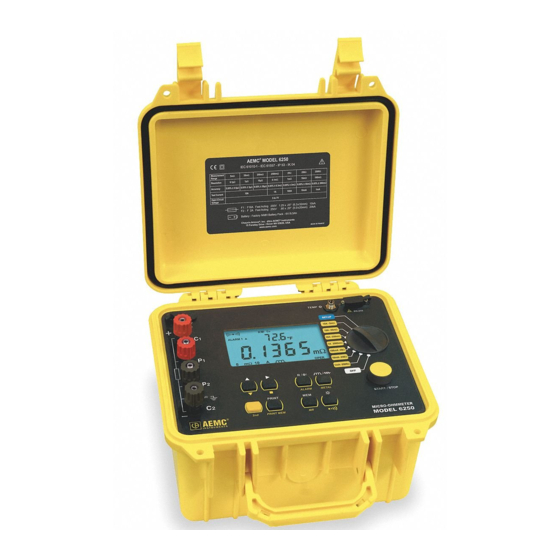
0.05%. A built-in circuit filters out AC signals. The Model 6250 Micro-ohmmeter is packaged in a sealed field case well suited for shop and field use. Power is supplied by a long-life NiMH battery pack with a built-in recharger (110/220V). -
Page 11: Applications
Direct display of the measurement with its units, range, measure- ment mode and, if activated, temperature compensation. • Measurement can be initiated from the front panel or remotely through the 9-pin communication port • Rugged, sealed case Micro-Ohmmeter Model 6250 0.561.8187 information@itm. www. .com... -
Page 12: Control Features
2. AC line recharging receptacle 3. Large multi-line backlit liquid crystal display 4. RTD temperature input 5. Communication /remote operation port 6. Range selection switch 7. Test, Start/Stop button 8. Eight program /function buttons Micro-Ohmmeter Model 6250 0.561.8187 information@itm. www. .com... -
Page 13: Button Functions
OFF and SET-UP positions. Data is viewed using the ▲ and ► buttons. The and ALARM buttons can be used. Turns the display backlight ON or OFF. Activates or deactivates the buzzer and adjusts the sound level. Micro-Ohmmeter Model 6250 0.561.8187 information@itm. www. .com... -
Page 14: Display Symbols
Second position locator for data stored in memory °C / °F Temperature displayed in either degrees Centigrade or Fahrenheit PRINT Printing current test result or tests stored in memory Displayed measurement about to be stored in memory Micro-Ohmmeter Model 6250 0.561.8187 information@itm. www. .com... - Page 15 2500 milliohm, 1 Amp test range selected 250mΩ 10A 250 milliohm, 10 Amp test range selected 25mΩ 10A 25 milliohm, 10 Amp test range selected 5mΩ 5 milliohm, 10 Amp test range selected Micro-Ohmmeter Model 6250 0.561.8187 information@itm. www. .com...
-
Page 16: Specifications
Accuracy: ± 0.5°C Resolution: 0.1°C Influence From Environment Conditions: Temperature: 0.1% per 10°C typical, 0.25% max Humidity: 0.5% max from 10 to 90% Battery Voltage: ± 0.1% from 4.5 to 7.5V Open Circuit Voltage: 7V Micro-Ohmmeter Model 6250 0.561.8187 information@itm. www. .com... -
Page 17: Mechanical
“temperature compensation” mode. The other contains 5 digits and is used to display the measured values on the bottom line. Error messages are also listed on the bottom line. Micro-Ohmmeter Model 6250 0.561.8187 information@itm. -
Page 18: Environmental
EN 61000-3-2 EN 61000-3-3 Immunity: EN 61000-4-2 electrostatic discharges EN 61000-4-3 radiated fields EN 61000-4-5 shock EN 61000-4-6 conducted disturbances EN 61000-4-11 voltage drops EN 61000-4-4 bursts *Specifications are subject to change without notice Micro-Ohmmeter Model 6250 0.561.8187 information@itm. www. .com... -
Page 19: Operation
6. Select the metal type for the device under test by pressing the yellow button followed by the METAL button. Successive presses of this two-button sequence will select Copper (Cu), Aluminum (Al) or Other metal. This will be needed for temperature compensation. Micro-Ohmmeter Model 6250 0.561.8187 information@itm. www. - Page 20 Typical Operational Display Temperature compensation active Buzzer active Metal type (Copper) Alarm 1 hi set point active Reference temperature Resistance measurement Measurement units Measurement range Test in process Test current Inductive test mode Figure 4-1 Micro-Ohmmeter Model 6250 0.561.8187 information@itm. www. .com...
-
Page 21: Instrument Configuration (Set-Up Mode)
The right arrow ► button selects the function displayed in the top level menu and moves the cursor one place to the right or validates the programming in the sub-menus. See Cables and Printer Used with the Interface Port (§5.3) for proper connections. Micro-Ohmmeter Model 6250 0.561.8187 information@itm. www. -
Page 22: Programming The 9-Pin Interface Port (Rs)
2. Trigger: Enables the remote measurement function. 3. PC: Activates an RS-232 link between a computer and the unit for configuring the Model 6250 and for conducting tests and storing results. When activated, the icon will appear on the display. -
Page 23: Setting The Buzzer Level (Buzz)
Press the ► button to display the firmware version. • Press the ► button again to return to the top level of the Software Version set-up menu. • To proceed to the next programming variable, press the ▲ button. Micro-Ohmmeter Model 6250 0.561.8187 information@itm. www. .com... -
Page 24: Setting Language For Printing Reports (Lang)
NOTE: The program limits for the reference temperature are 32.0 to 130.0°F and -10.0 to 130.0°C. Attempting to set values outside these limits will cause error message “Err23” (Entry Out of Range) to appear in the display. Micro-Ohmmeter Model 6250 0.561.8187 information@itm. www. -
Page 25: Selecting The Method/Value For Ambient Temp
NOTE: The program limits for the reference temperature are 32.0 to 130.0°F and -10.0 to 130.0°C. Attempting to set values outside these limits will cause error message “Err23” (Entry Out of Range) to appear in the display. Micro-Ohmmeter Model 6250 0.561.8187 information@itm. www. -
Page 26: Selecting The Metal Type (Neta)
To proceed to the next programming variable, press the ▲ button. 4.2.11 Selecting Temperature Units (dEg) • Turn the rotary switch to the SET-UP position. • Press the ▲ button until “dEg” appears on the top line of the dis- play. Micro-Ohmmeter Model 6250 0.561.8187 information@itm. www. .com... -
Page 27: Setting Alarm Set Point/Direction/Buzzer Level
To accept the alarm settings once the decimal point and units are at the desired values, press the ► button. This will bring you to Alarm 2. Repeat the process as necessary to set Alarm 2’s conditions. Micro-Ohmmeter Model 6250 0.561.8187 information@itm. www. -
Page 28: Setting The Display Timeout (Llgh)
Use the arrow buttons to select the object to be deleted. • The lower display will show “dEL.02” for example if object number 2 is selected for deletion. As you press the ▲ button, the selected object will increment accordingly. Micro-Ohmmeter Model 6250 0.561.8187 information@itm. www. .com... - Page 29 NOTE: Only objects with data stored in them can be accessed. To return to the beginning of the SET-UP menu, press the ▲ button when “nEn” is on the top line of the display Micro-Ohmmeter Model 6250 0.561.8187 information@itm. www.
-
Page 30: Operating Procedure
A diagram of the measurement system is shown in Figure 4-2. The Model 6250 generates a current (I) from the internal voltage source (V). A voltmeter measures the voltage drop V at the Kelvin probe contact... -
Page 31: Test Lead Connection
On very large samples such as utility transformers, 10 to 15 minutes charging time may be necessary. Micro-Ohmmeter Model 6250 0.561.8187 information@itm. -
Page 32: Stand-By (St By) State
4.3.5 Stand-by (ST BY) State This is the position that the Model 6250 returns to at the end of a measure- ment cycle after: • the operator presses the START/STOP button during a test • any changes to the position of the rotary switch •... -
Page 33: Measurement Modes
“Err 11” (current leads incorrectly connected), or “Err 12” (voltage leads incorrectly connected). The unit will then return to the Stand-by state. When the error is corrected, the test automatically begins again. Micro-Ohmmeter Model 6250 0.561.8187 information@itm. www. - Page 34 The timing sequence for measurement is shown in Figure 4-5. NOTE: After ending the measurement, with the current turned off, the 6250 will discharge the device under test as long as the test leads are connected to the device.
-
Page 35: Resistance Measurement Mode
) is measured and then the current is removed. • The measurement resistance result R = (V ) / I is displayed or error message “Err 07” is displayed, if an over range condition occurs. Micro-Ohmmeter Model 6250 0.561.8187 information@itm. www. .com... -
Page 36: Low Inductive Resistance Measurement Mode
The Model 6250 then returns to the Stand-by state at the end of the mea- surement. The unit is ready to perform another measurement. OPER STBY 100ms 100ms 240ms 240ms 360ms 360ms Figure 4-6 C = connection check 0 = residual voltage measurement M = measurement of the voltage across the resistor terminals. -
Page 37: Ambient Temperature Compensation
Its purpose is to compensate the measured or resistance value at the ambient temperature (whether measured or programmed), to the resis- tance value that it should have at a reference temperature. Micro-Ohmmeter Model 6250 0.561.8187 information@itm. www. .com... - Page 38 The Alpha values for Copper and Aluminum are pre-programmed into the Model 6250. Others may be programmed by selecting Other Metals and then programming in the alpha constant from the table or other sources. “alpha” per °C...
- Page 39 Figure 4-7. Pt100 connector Figure 4-7 To measure the ambient air temperature at the Model 6250, plug the optional temperature sensor directly into the temperature port on the front panel as shown in Figure 4-8.
-
Page 40: Activating The Compensation Function
• The unit performs a measurement cycle and directly displays the compensated resistance value and, depending on set-up, displays one of the following: 1. The programmed ambient temperature level 2. The temperature level measured by the temperature sensor Micro-Ohmmeter Model 6250 0.561.8187 information@itm. www. .com... -
Page 41: Activating Alarms
4. The measured temperature is out of range (-10° to 55°C) If the temperature is out of range or if the sensor leads are disconnected, the Model 6250 displays “Err 10”. Temperature compensation can be toggled ON or OFF after the mea- surement is completed, in resistive and inductive modes or at any time in AUTO mode. -
Page 42: Memory / Printing
If an occupied location is selected, the OCC message blinks to warn that this memory location is already taken. Storage action in this location requires pressing the MEM button again. The previous measurement in this location will be replaced by the new measurement. Micro-Ohmmeter Model 6250 0.561.8187 information@itm. www. -
Page 43: Displaying And Printing Stored Measurements
Press the PRINT button to print the measurement results stored at • the current memory location. An optional serial printer is required for this feature. Micro-Ohmmeter Model 6250 0.561.8187 information@itm. www. .com... - Page 44 Figure 5-1 Enclosed with this manual is a pad containing 50 forms to record the measurement results manually. They may be photocopied as needed or downloaded from our website at www.aemc.com/techinfo/index.asp located in the Micro-ohmmeter section. Micro-Ohmmeter Model 6250 0.561.8187 information@itm.
-
Page 45: Cables And Printers Used With The Interface Port
The main connection pins used are detailed in Figures 5-3 and 5-4 respectively. Connection to a PC or Terminal: Figure 5-3 Male Connector Female Connector Printer end Printer end 6250 end Micro-Ohmmeter Model 6250 0.561.8187 information@itm. www. .com... - Page 46 For a Direct Printer Connection: Figure 5-4 Male Connector Female Connector Printer end Printer end Micro-Ohmmeter Model 6250 0.561.8187 information@itm. www. .com...
-
Page 47: Dataview ® Software
USB Flash Drive Install 1. Insert the USB stick into an available USB port (wait for driver to be installed). 2. If Autorun is enabled then an AutoPlay window should appear as shown. Micro-Ohmmeter Model 6250 0.561.8187 information@itm. www. .com... - Page 48 Select the Allow option to proceed. 5. A Set-up window, similar to the one below, will appear. Figure 6-1 There are several different options to choose from. Some options require an internet connection. Micro-Ohmmeter Model 6250 0.561.8187 information@itm. www. .com...
- Page 49 11. In the Select Features window that appears, select the instrument’s control panel that you want to install, then click Next. NOTE: The PDF-XChange option must be selected to be able to generate PDF reports from within DataView ® Micro-Ohmmeter Model 6250 0.561.8187 information@itm. www. .com...
- Page 50 15. Next, the Installation Wizard Complete window will appear. Click on Finish. 16. A Question dialog box appears next. Click Yes to read the procedure for connecting the instrument to the USB port on the computer. Micro-Ohmmeter Model 6250 0.561.8187 information@itm. www.
-
Page 51: Connecting The Instrument To Your Computer
To connect the instrument to your computer, connect one end of the serial cable to the communications port on the Model 6250 and the other end to the port on the computer. Establishing Communication to the Instrument 1. -
Page 52: Configuring The Instrument
• Temperature Correction: Enables and disables compensation of resistance measurements based on temperature. • Ambient Temperature: Allows User to enter the ambient temperature or use the PT100 temperature probe to measure the Micro-Ohmmeter Model 6250 0.561.8187 information@itm. www. .com... - Page 53 Cancel: Closes the Configuration dialog box and brings up the Control Panel. Once all of the fields have been configured, click on the Write to Instru- ment button to configure the instrument and close the Configuration dialog box. Micro-Ohmmeter Model 6250 0.561.8187 information@itm. www. .com...
-
Page 54: Downloading Stored Tests
Report ® 1. Download a stored test (see § 6.5) 2. Select the test to create the DataView report for. ® 3. Go to File > Create DataView Report from the main menu. Micro-Ohmmeter Model 6250 0.561.8187 information@itm. www. .com... -
Page 55: Exporting The Report To A Spreadsheet Or Pdf File
Then, type a file name in the File name field at the bottom and click Save. NOTE: For additional help on using the software, use DataView’s “Help” Menu, which is located on the menu bar. Micro-Ohmmeter Model 6250 0.561.8187 information@itm. www. -
Page 56: Troubleshooting
CHAPTER 7 TROUBLESHOOTING The Model 6250 incorporates internal diagnostics and will inform the oper- ator of any condition needing attention through the use of error messages. The available messages are described here. Fault Indicators Err 1 Low battery level Err 2... -
Page 57: Application Examples
CHAPTER 8 APPLICATION EXAMPLES The proper procedures for using the Model 6250 in some specific applica- tions are outlined throughout this section. Measuring Winding Resistance of Motors and Transformers WARNING: Prior to and after testing a transformer winding, the energy stored in the magnetic field must be dissipated by shorting the trans- former terminals. -
Page 58: Measuring Resistance On Electric Motors
Each individual cell resistance should not exceed the average by more than 10%. See the manufacturer’s specifications for typical resistance values. Battery Battery Figure 8-3 Micro-Ohmmeter Model 6250 0.561.8187 information@itm. www. .com... -
Page 59: Maintenance
CHAPTER 9 MAINTENANCE Use only factory specified replacement parts. AEMC will not be held ® responsible for any accident, incident, or malfunction following a repair done other than by its service center or by an approved repair center. Warning •... -
Page 60: Charging/Recharging The Battery
110V line cord, which provides the charging voltage for the rechargeable battery. CHARGING THE BATTERY The Model 6250 should be charged to a full charge before using it for the first time. Charging to full capacity may take up to 6 hours for a completely discharged battery If the battery symbol is flashing, the battery needs to be recharged. -
Page 61: Battery And Fuse Replacement
Fuse F1, is a 6.3x32 mm, fast acting, 16A/250V, low internal resistance, protecting the current source from outside voltages on energized specimens. • Fuse F2, is a 5.0x20 mm, fast acting, 2A/250V, protecting the battery charger power supply board. Micro-Ohmmeter Model 6250 0.561.8187 information@itm. www. .com... - Page 62 0.561.8187 information@itm. www. .com...
-
Page 63: Limited Warranty
Limited Warranty The Micro-ohmmeter Model 6250 is warranted to the owner for a period of one year from the date of original purchase against defects in manufacture. This limited warranty is given by AEMC Instruments, not by the distributor from ®... - Page 64 2/16 99-MAN 100288 v23 Chauvin Arnoux , Inc. d.b.a. AEMC Instruments ® ® 0.561.8187 information@itm. www. .com...
Need help?
Do you have a question about the 6250 and is the answer not in the manual?
Questions and answers